EP1137958B1 - Coated lens exhibiting substantially balanced reflectance - Google Patents
Coated lens exhibiting substantially balanced reflectance Download PDFInfo
- Publication number
- EP1137958B1 EP1137958B1 EP99957748A EP99957748A EP1137958B1 EP 1137958 B1 EP1137958 B1 EP 1137958B1 EP 99957748 A EP99957748 A EP 99957748A EP 99957748 A EP99957748 A EP 99957748A EP 1137958 B1 EP1137958 B1 EP 1137958B1
- Authority
- EP
- European Patent Office
- Prior art keywords
- lens
- centre
- coating
- reflectance
- edge
- Prior art date
- Legal status (The legal status is an assumption and is not a legal conclusion. Google has not performed a legal analysis and makes no representation as to the accuracy of the status listed.)
- Expired - Lifetime
Links
- 230000001747 exhibiting effect Effects 0.000 title claims 3
- 238000000576 coating method Methods 0.000 claims abstract description 55
- 239000011248 coating agent Substances 0.000 claims abstract description 48
- 230000003287 optical effect Effects 0.000 claims abstract description 12
- VYPSYNLAJGMNEJ-UHFFFAOYSA-N Silicium dioxide Chemical compound O=[Si]=O VYPSYNLAJGMNEJ-UHFFFAOYSA-N 0.000 claims description 18
- GWEVSGVZZGPLCZ-UHFFFAOYSA-N Titan oxide Chemical compound O=[Ti]=O GWEVSGVZZGPLCZ-UHFFFAOYSA-N 0.000 claims description 16
- 239000000758 substrate Substances 0.000 claims description 16
- 229910052681 coesite Inorganic materials 0.000 claims description 9
- 229910052906 cristobalite Inorganic materials 0.000 claims description 9
- 238000000034 method Methods 0.000 claims description 9
- 239000000377 silicon dioxide Substances 0.000 claims description 9
- 229910052682 stishovite Inorganic materials 0.000 claims description 9
- 229910052905 tridymite Inorganic materials 0.000 claims description 9
- 239000011347 resin Substances 0.000 claims description 4
- 229920005989 resin Polymers 0.000 claims description 4
- 230000000007 visual effect Effects 0.000 abstract description 3
- 238000000151 deposition Methods 0.000 description 9
- 238000000985 reflectance spectrum Methods 0.000 description 9
- 230000008021 deposition Effects 0.000 description 8
- 238000001228 spectrum Methods 0.000 description 6
- 239000000463 material Substances 0.000 description 5
- 235000012239 silicon dioxide Nutrition 0.000 description 5
- 230000003667 anti-reflective effect Effects 0.000 description 4
- JHQVCQDWGSXTFE-UHFFFAOYSA-N 2-(2-prop-2-enoxycarbonyloxyethoxy)ethyl prop-2-enyl carbonate Chemical compound C=CCOC(=O)OCCOCCOC(=O)OCC=C JHQVCQDWGSXTFE-UHFFFAOYSA-N 0.000 description 3
- 230000000694 effects Effects 0.000 description 3
- 230000004907 flux Effects 0.000 description 3
- 239000010410 layer Substances 0.000 description 3
- 229920000515 polycarbonate Polymers 0.000 description 3
- 239000004417 polycarbonate Substances 0.000 description 3
- 230000003595 spectral effect Effects 0.000 description 3
- 239000010409 thin film Substances 0.000 description 3
- 238000001429 visible spectrum Methods 0.000 description 3
- 241001282110 Pagrus major Species 0.000 description 2
- 239000011247 coating layer Substances 0.000 description 2
- 150000002500 ions Chemical class 0.000 description 2
- 238000004519 manufacturing process Methods 0.000 description 2
- 238000005259 measurement Methods 0.000 description 2
- 239000002245 particle Substances 0.000 description 2
- 230000035945 sensitivity Effects 0.000 description 2
- 238000005299 abrasion Methods 0.000 description 1
- 229920006397 acrylic thermoplastic Polymers 0.000 description 1
- 125000000746 allylic group Chemical group 0.000 description 1
- 239000003086 colorant Substances 0.000 description 1
- 230000007812 deficiency Effects 0.000 description 1
- 230000001066 destructive effect Effects 0.000 description 1
- 239000010408 film Substances 0.000 description 1
- 238000009501 film coating Methods 0.000 description 1
- 230000002209 hydrophobic effect Effects 0.000 description 1
- 239000011261 inert gas Substances 0.000 description 1
- 238000002329 infrared spectrum Methods 0.000 description 1
- 238000010884 ion-beam technique Methods 0.000 description 1
- 239000004033 plastic Substances 0.000 description 1
- 229920003023 plastic Polymers 0.000 description 1
- 229920003229 poly(methyl methacrylate) Polymers 0.000 description 1
- 229920000728 polyester Polymers 0.000 description 1
- 238000002360 preparation method Methods 0.000 description 1
- -1 styrenics Polymers 0.000 description 1
- ISXSCDLOGDJUNJ-UHFFFAOYSA-N tert-butyl prop-2-enoate Chemical compound CC(C)(C)OC(=O)C=C ISXSCDLOGDJUNJ-UHFFFAOYSA-N 0.000 description 1
- 239000004753 textile Substances 0.000 description 1
- 238000001771 vacuum deposition Methods 0.000 description 1
- 238000007738 vacuum evaporation Methods 0.000 description 1
- 125000002348 vinylic group Chemical group 0.000 description 1
- 235000012431 wafers Nutrition 0.000 description 1
Images
Classifications
-
- G—PHYSICS
- G02—OPTICS
- G02B—OPTICAL ELEMENTS, SYSTEMS OR APPARATUS
- G02B1/00—Optical elements characterised by the material of which they are made; Optical coatings for optical elements
- G02B1/10—Optical coatings produced by application to, or surface treatment of, optical elements
- G02B1/11—Anti-reflection coatings
- G02B1/113—Anti-reflection coatings using inorganic layer materials only
- G02B1/115—Multilayers
-
- B—PERFORMING OPERATIONS; TRANSPORTING
- B29—WORKING OF PLASTICS; WORKING OF SUBSTANCES IN A PLASTIC STATE IN GENERAL
- B29D—PRODUCING PARTICULAR ARTICLES FROM PLASTICS OR FROM SUBSTANCES IN A PLASTIC STATE
- B29D11/00—Producing optical elements, e.g. lenses or prisms
- B29D11/00865—Applying coatings; tinting; colouring
-
- G—PHYSICS
- G02—OPTICS
- G02B—OPTICAL ELEMENTS, SYSTEMS OR APPARATUS
- G02B27/00—Optical systems or apparatus not provided for by any of the groups G02B1/00 - G02B26/00, G02B30/00
- G02B27/0012—Optical design, e.g. procedures, algorithms, optimisation routines
-
- Y—GENERAL TAGGING OF NEW TECHNOLOGICAL DEVELOPMENTS; GENERAL TAGGING OF CROSS-SECTIONAL TECHNOLOGIES SPANNING OVER SEVERAL SECTIONS OF THE IPC; TECHNICAL SUBJECTS COVERED BY FORMER USPC CROSS-REFERENCE ART COLLECTIONS [XRACs] AND DIGESTS
- Y10—TECHNICAL SUBJECTS COVERED BY FORMER USPC
- Y10T—TECHNICAL SUBJECTS COVERED BY FORMER US CLASSIFICATION
- Y10T428/00—Stock material or miscellaneous articles
- Y10T428/31504—Composite [nonstructural laminate]
- Y10T428/3154—Of fluorinated addition polymer from unsaturated monomers
-
- Y—GENERAL TAGGING OF NEW TECHNOLOGICAL DEVELOPMENTS; GENERAL TAGGING OF CROSS-SECTIONAL TECHNOLOGIES SPANNING OVER SEVERAL SECTIONS OF THE IPC; TECHNICAL SUBJECTS COVERED BY FORMER USPC CROSS-REFERENCE ART COLLECTIONS [XRACs] AND DIGESTS
- Y10—TECHNICAL SUBJECTS COVERED BY FORMER USPC
- Y10T—TECHNICAL SUBJECTS COVERED BY FORMER US CLASSIFICATION
- Y10T428/00—Stock material or miscellaneous articles
- Y10T428/31504—Composite [nonstructural laminate]
- Y10T428/3154—Of fluorinated addition polymer from unsaturated monomers
- Y10T428/31544—Addition polymer is perhalogenated
Definitions
- the present invention relates to an optical lens with a coating which displays superior uniformity of reflection.
- optical lenses according to the present invention are preferably employed in the preparation of articles such as spectacle lenses, including sunglass lenses, visors, shields, and the like.
- Anti-reflection coatings are commonly deposited on ophthalmic and sunglass lenses in order to minimise spurious reflections, which both detract from the wearer's vision and are also cosmetically unpleasing. These coatings commonly consist of multilayer, dielectric films of thicknesses chosen so that interference effects cause destructive cancellation of reflections over most of the visible spectrum.
- a coating that is not anti-reflective and that changes the reflectance of the lens can be described as a "mirror" coating.
- Such mirror coatings are often used in the manufacture of sunglass lenses, to produce fashionable lens colours.
- curved substrates such as ophthalmic lenses
- geometrical factors result in the coating thickness being non-uniform and varying systematically over the surface of the lens.
- the coating thickness is typically greatest where the surface of the substrate is most normal to the incident flux of particles, and thinner where the surface faces the flux at an angle.
- ophthalmic lenses which are normally mounted with their centres facing the particle source, this means a coating that is thickest in the centre and that becomes thinner towards the edge of the lens element. This effect becomes more pronounced as the lens becomes more highly curved.
- the coating thickness variations manifest themselves as visible variations in the reflectance from the coated lens.
- the colour (specified by “lightness”, “hue” and “chroma) of the residual reflection changes from the centre to the edge of the lens, an effect referred to as “colour rolloff.”
- colour rolloff For lenses of normal curvature, the colour rolloff is barely noticeable and cosmetically, the lenses are considered to be acceptable. However, for very highly curved lenses, the colour rolloff is particularly noticeable and is generally considered to be unsatisfactory.
- Prior art lens coatings are known from DE 29505497 , JP 10-160906 , US 3781090 and US 4070097 , and a method of coating a lens is disclosed in US 5225057 .
- an optical lens as claimed in claim 1.
- the lens element may be either optically clear or tinted (light absorbing), such as a sunglass lens, ophthalmic lens element, visor or the like.
- ophthalmic lens element we mean all forms of individual refractive optical bodies employed in the ophthalmic arts, including, but not limited to, lenses, lens wafers and semi-finished lens blanks requiring further finishing to a particular patient's prescription.
- the visual appearance of the coated optical lens in reflected light can be quantified by measuring its reflectance spectrum in a spectrophotometer. It is well known that the reflectance of thin film coatings tends to vary with the angle of the incident light. When we speak of the reflectance from the lens we imply the reflectance of light incident at angles of 0 to approximately 30 degrees to the normal to the surface of the lens, as would typically be the case for the reflected light seen by an observer standing directly in front of a person wearing the coated lenses as spectacles.
- This spectral information may be reduced to three colour coordinates - a "lightness" corresponding primarily to the luminous intensity of the reflected light, and two chromatic attributes, "hue” and “chroma”, corresponding to the general colour (e.g. "red, "blue", “green” etc.) and its vividness.
- the Measurement of Appearance 2nd ed., R.S. Hunter and R.W. Harold, Wiley, New York, 1987 ).
- substantially balanced reflectance we mean that where the thickness of the coating varies across the surface of the lens, the lightness, hue and chroma of the reflectance vary in a balanced manner such that variations in visual appearance are either imperceptible or generally acceptable to an observer. For example, variations in chromatic attributes, such as hue, from the centre to the edge of the lens may be balanced by a reduction in lightness from the centre to the edge.
- CMC colour differences as developed by the Colour Measurement Committee of the Society of Dyers and Colourists.
- the reflectance of light of essentially normal incidence measured at the centre of the lens element is low in the visible spectrum (roughly 380-780 nm), but is significantly greater for longer wavelengths.
- the total coating thickness may be reduced to 80% of the thickness at the centre of the lens. This is due to the curvature of the lens and the geometry of the deposition system as described above. As shown in the figure, the spectrum shifts to the left relative to the spectrum from the centre of the lens. This is a well-known phenomenon to those familiar with the art and theory of thin films.
- the balanced reflectance coating according to the present invention has a substantially more uniform appearance from the centre to the edge of the lens element (see Figure 2 below).
- Figure 2 compares the reflectance spectra at the centre and at a radial distance of 20 mm from the centre on a 16 dioptre lens now coated with the roll-off-resistant coating.
- this coating at the centre of the lens
- the lens displays relatively little colour roll-off. The lens changes from light blue in the centre to pale blue/purple at the edges and is quite acceptable.
- the photopic reflectance is less than approximately 3%.
- the reflectance is preferably low where the eye is most sensitive, in the region of approximately 550 nm.
- the low reflectance in the near infra-red spectrum is clearly an important characteristic of the balanced reflectance coating, but for certain coloured coatings this alone may not ensure that it displays acceptable colour roll-off eg. on a highly curved lens. For example, if the coating displays a red colour in the centre of the lens, even if the reflectance in the near infra-red is low, the colour will roll through yellow and green as the thickness rolls off from centre to edge of the lens. If a uniform hue is desired the roll-off will not be acceptable.
- the lens will exhibit acceptable colour roll-off, because the colour roll-off is balanced by luminous reflectance roll-off (as opposed to hue) which is acceptable.
- the ophthalmic lenses may be formed from a variety of different lens materials, and particularly from a number of different polymeric plastic resins.
- a common ophthalmic lens material is diethylene glycol bis (allyl carbonate) or CR39 (PPG Industries). Lens materials with higher refractive indices are now growing in popularity.
- Other examples of lens materials that may be suitable for use with the invention include other acrylics, other allylics, styrenics, polycarbonates, vinylics, polyesters and the like.
- the optical article may be a sunglass lens of the wrap-around or visor type, for example of the type described in International Patent Application PCT/AU97/00188 "Improved Single Vision Lens" to Applicants.
- the deposition step may be a vacuum deposition step.
- the deposition step may be conducted in a coating apparatus.
- a box coater or sputter coater may be used.
- the balanced reflectance coating may preferably be formed on the surfaces of the substrate according to the process and the box coaters as described in the Italian Patent No. 1.244.374 .
- the various layers of the balanced reflectance coating may be deposited in subsequent steps utilising a vacuum evaporation technique and exposing the growing layers to a bombardment of a beam of ions of inert gas.
- the deposition of the layers may be achieved at a low temperature (generally below 80°C), using an ion beam having a medium intensity (meaning the average number of ions that reach the substrate) included between approximately 30 and 100 ⁇ A/cm2 and the energy included between approximately 50 and 100 eV.
- a medium intensity meaning the average number of ions that reach the substrate
- Figure 1 illustrates a measured reflectance spectrum (for light at normal incidence) of a 16 dioptre polycarbonate lens coated on both sides with an abrasion-resistant coating and a typical commercial multilayer, anti-reflection coating.
- the reflectance at the centre of the lens is low in the visible spectrum (roughly 380-780 nm), but is significantly greater for longer wavelengths.
- the spectrum shifts to the left relative to the spectrum from the centre of the lens. This is a well-known phenomenon to those familiar with the art and theory of thin films.
- the higher reflectance "red tail" seen in Figure 1 moves further into the region of spectral sensitivity of the human eye and causes the appearance of the lens to redden toward the edges.
- the lens displays substantial colour roll-off, changing from faint green in the centre to bright red/orange at the edges and is unacceptable.
- Table 2 shows the optical design for an anti-reflection coating whose reflected colour, particularly its hue, is robust to colour roll-off when its thickness varies.
- Figure 2 compares the reflectance spectra measured at the centre and at a radius of 20 mm on a 16 dioptre CR39 lens coated on both sides with the balanced reflectance coating.
- this coating at the centre of the lens
- the lens displays relatively little colour roll-off, particularly in its hue.
- the luminous intensity of the reflection concurrently reduces from 3.4% to 1.8%.
Landscapes
- Physics & Mathematics (AREA)
- General Physics & Mathematics (AREA)
- Optics & Photonics (AREA)
- Engineering & Computer Science (AREA)
- Inorganic Chemistry (AREA)
- Chemical & Material Sciences (AREA)
- Health & Medical Sciences (AREA)
- Manufacturing & Machinery (AREA)
- Ophthalmology & Optometry (AREA)
- Mechanical Engineering (AREA)
- Eyeglasses (AREA)
- Surface Treatment Of Optical Elements (AREA)
- Aerials With Secondary Devices (AREA)
- Casting Or Compression Moulding Of Plastics Or The Like (AREA)
- Dental Preparations (AREA)
Abstract
Description
- The present invention relates to an optical lens with a coating which displays superior uniformity of reflection.
- The optical lenses according to the present invention are preferably employed in the preparation of articles such as spectacle lenses, including sunglass lenses, visors, shields, and the like.
- Anti-reflection coatings are commonly deposited on ophthalmic and sunglass lenses in order to minimise spurious reflections, which both detract from the wearer's vision and are also cosmetically unpleasing. These coatings commonly consist of multilayer, dielectric films of thicknesses chosen so that interference effects cause destructive cancellation of reflections over most of the visible spectrum.
- A coating that is not anti-reflective and that changes the reflectance of the lens can be described as a "mirror" coating. Such mirror coatings are often used in the manufacture of sunglass lenses, to produce fashionable lens colours.
- When mirror and anti-reflection coatings are deposited on curved substrates (such as ophthalmic lenses), regardless of the deposition method used (eg. evaporative, sputtered, etc.) geometrical factors result in the coating thickness being non-uniform and varying systematically over the surface of the lens. The coating thickness is typically greatest where the surface of the substrate is most normal to the incident flux of particles, and thinner where the surface faces the flux at an angle. For ophthalmic lenses, which are normally mounted with their centres facing the particle source, this means a coating that is thickest in the centre and that becomes thinner towards the edge of the lens element. This effect becomes more pronounced as the lens becomes more highly curved.
- The coating thickness variations manifest themselves as visible variations in the reflectance from the coated lens. The colour (specified by "lightness", "hue" and "chroma") of the residual reflection changes from the centre to the edge of the lens, an effect referred to as "colour rolloff." For lenses of normal curvature, the colour rolloff is barely noticeable and cosmetically, the lenses are considered to be acceptable. However, for very highly curved lenses, the colour rolloff is particularly noticeable and is generally considered to be unsatisfactory.
- One method proposed in the prior art to reduce colour rolloff is to mount the substrate on a "planetary rotation" stage, which spins the lens about its own axis at the same time that it rotates about another central axis. The result of the complex substrate motion in the deposition chamber is that the flux of coating material is more evenly distributed over the surface of the lens, resulting in a coating that is more uniform over the substrate than would otherwise be the case. Planetary rotation is not the only option - any substrate motion at all will tend to reduce coating thickness non-uniformities. Unfortunately, implementing such substrate movement in the deposition chamber necessary involves mechanical complexity and a likely decrease in the total number of substrates that can be coated simultaneously in the apparatus, which is a severe disadvantage in a commercial production process.
- Prior art lens coatings are known from
DE 29505497 ,JP 10-160906 US 3781090 andUS 4070097 , and a method of coating a lens is disclosed inUS 5225057 . - It would accordingly be a significant advance in the art if ophthalmic lenses could be provided with a coating or coatings of general applicability which could reduce the phenomenon of "colour rolloff", but without the need for "planetary rotation" apparatus.
- Accordingly, it is an object of the present invention to overcome, or at least alleviate, one or more of the difficulties or deficiencies related to the prior art.
- Accordingly, in a first aspect of the present invention there is provided an optical lens as claimed in claim 1.
- The lens element may be either optically clear or tinted (light absorbing), such as a sunglass lens, ophthalmic lens element, visor or the like.
- By the term "ophthalmic lens element", as used herein, we mean all forms of individual refractive optical bodies employed in the ophthalmic arts, including, but not limited to, lenses, lens wafers and semi-finished lens blanks requiring further finishing to a particular patient's prescription.
- The visual appearance of the coated optical lens in reflected light can be quantified by measuring its reflectance spectrum in a spectrophotometer. It is well known that the reflectance of thin film coatings tends to vary with the angle of the incident light. When we speak of the reflectance from the lens we imply the reflectance of light incident at angles of 0 to approximately 30 degrees to the normal to the surface of the lens, as would typically be the case for the reflected light seen by an observer standing directly in front of a person wearing the coated lenses as spectacles. This spectral information may be reduced to three colour coordinates - a "lightness" corresponding primarily to the luminous intensity of the reflected light, and two chromatic attributes, "hue" and "chroma", corresponding to the general colour (e.g. "red, "blue", "green" etc.) and its vividness. ("The Measurement of Appearance", 2nd ed., R.S. Hunter and R.W. Harold, Wiley, New York, 1987).
- By the term "substantially balanced reflectance" we mean that where the thickness of the coating varies across the surface of the lens, the lightness, hue and chroma of the reflectance vary in a balanced manner such that variations in visual appearance are either imperceptible or generally acceptable to an observer. For example, variations in chromatic attributes, such as hue, from the centre to the edge of the lens may be balanced by a reduction in lightness from the centre to the edge.
- Perceived variations in appearance may be quantified by calculating "CMC colour differences," as developed by the Colour Measurement Committee of the Society of Dyers and Colourists. A CMC colour variation of ΔECMC(2:1)=1 is the limit of acceptability for textiles. Applicants have found that this is too stringent a tolerance for anti-reflection or mirror coated lenses in the ophthalmic industry. Variations between anti-reflection coated lenses of approximately 3 or less are acceptable and Applicants have observed that colour differences of up to 3-11 may exist across a lens that has an acceptably uniform appearance. Variations of up to 20 may exist in lenses that are visibly non-uniform in colour, yet that are still acceptable in appearance.
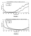
- The normal incidence reflectance spectrum of a highly curved (16 dioptre) lens coated with a typical commercial anti-reflection coating is shown in
Figure 1 . - The reflectance of light of essentially normal incidence measured at the centre of the lens element is low in the visible spectrum (roughly 380-780 nm), but is significantly greater for longer wavelengths. Toward the edge of the lens element (eg. at a radius of 20 mm from the centre), the total coating thickness may be reduced to 80% of the thickness at the centre of the lens. This is due to the curvature of the lens and the geometry of the deposition system as described above. As shown in the figure, the spectrum shifts to the left relative to the spectrum from the centre of the lens. This is a well-known phenomenon to those familiar with the art and theory of thin films. As a consequence, the higher reflectance "red tail" seen in
Figure 1 moves further into the region of spectral sensitivity of the human eye and causes the appearance of the lens to redden toward the edges. The CMC colour difference (for CIE illuminant C) between the centre of the lens and at the radius of 20 mm is ΔECMC(2:1)=27. The lens displays substantial colour roll-off, changing from faint green in the centre to bright red/orange at the edges and is unacceptable. - In contrast, the balanced reflectance coating according to the present invention has a substantially more uniform appearance from the centre to the edge of the lens element (see
Figure 2 below). -
Figure 2 compares the reflectance spectra at the centre and at a radial distance of 20 mm from the centre on a 16 dioptre lens now coated with the roll-off-resistant coating. In contrast to the previous standard anti-reflection coating, this coating (at the centre of the lens) exhibits substantially lower photopic reflectance at longer wavelengths. Indeed, it is anti-reflective beyond 880 nm. When the coating thickness reduces away from the centre of the lens and the reflectance spectrum shifts to the left, relatively little intensity is introduced in the red region of the spectrum. The CMC colour difference (for CIE illuminant C) between the centre of the lens and at the radius of 20 mm is ΔECMC(2:1)=10. The lens displays relatively little colour roll-off. The lens changes from light blue in the centre to pale blue/purple at the edges and is quite acceptable. - This may be achieved, inter alia, by providing a balanced reflectance coating for a lens element which, in use, exhibits a substantially constant low photopic reflectance in the red-to-infra-red wavelength range of approximately 620 to 880 nm proximate the centre of the lens element.
- Preferably, the photopic reflectance is less than approximately 3%. The reflectance is preferably low where the eye is most sensitive, in the region of approximately 550 nm.
- The low reflectance in the near infra-red spectrum is clearly an important characteristic of the balanced reflectance coating, but for certain coloured coatings this alone may not ensure that it displays acceptable colour roll-off eg. on a highly curved lens. For example, if the coating displays a red colour in the centre of the lens, even if the reflectance in the near infra-red is low, the colour will roll through yellow and green as the thickness rolls off from centre to edge of the lens. If a uniform hue is desired the roll-off will not be acceptable. If, however, a multicoloured lens, which is still functionally anti-reflective as its hue changes is the desired result, then the lens will exhibit acceptable colour roll-off, because the colour roll-off is balanced by luminous reflectance roll-off (as opposed to hue) which is acceptable.
- Where the lens element is an ophthalmic lens element, the ophthalmic lenses may be formed from a variety of different lens materials, and particularly from a number of different polymeric plastic resins. A common ophthalmic lens material is diethylene glycol bis (allyl carbonate) or CR39 (PPG Industries). Lens materials with higher refractive indices are now growing in popularity. Other examples of lens materials that may be suitable for use with the invention include other acrylics, other allylics, styrenics, polycarbonates, vinylics, polyesters and the like.
- The optical article may be a sunglass lens of the wrap-around or visor type, for example of the type described in International Patent Application
PCT/AU97/00188 - In a further aspect of the present invention, there is provided a method for preparing a coated optical lens, as claimed in claim 2.
- The deposition step may be a vacuum deposition step. The deposition step may be conducted in a coating apparatus. A box coater or sputter coater may be used.
- The balanced reflectance coating may preferably be formed on the surfaces of the substrate according to the process and the box coaters as described in the Italian Patent No.
1.244.374 - In accordance with said method, the various layers of the balanced reflectance coating may be deposited in subsequent steps utilising a vacuum evaporation technique and exposing the growing layers to a bombardment of a beam of ions of inert gas.
- Moreover, in accordance with the preferred method, the deposition of the layers may be achieved at a low temperature (generally below 80°C), using an ion beam having a medium intensity (meaning the average number of ions that reach the substrate) included between approximately 30 and 100 µA/cm2 and the energy included between approximately 50 and 100 eV.
- Further characteristics and advantages of the present invention will be apparent from the following description of drawings and examples of embodiments of the present invention, given as indicative but not restrictive.
- In the figures:
-
Figure 1 illustrates a measured reflectance spectrum (for light at normal incidence) of a lens coated on both sides with a known multilayer, anti-reflection coating. -
Figure 2 illustrates a measured reflectance spectrum (for light at normal incidence) of a lens corresponding to the present invention. -
Figure 1 illustrates a measured reflectance spectrum (for light at normal incidence) of a 16 dioptre polycarbonate lens coated on both sides with an abrasion-resistant coating and a typical commercial multilayer, anti-reflection coating. - The reflectance at the centre of the lens is low in the visible spectrum (roughly 380-780 nm), but is significantly greater for longer wavelengths. Toward the edge (at a radius of 20 mm), the total coating thickness is reduced to 80% of the thickness at the centre of the lens. This is due to the curvature of the lens and the geometry of the deposition system, a Satis 1200 evaporative box coater. As shown in the figure, the spectrum shifts to the left relative to the spectrum from the centre of the lens. This is a well-known phenomenon to those familiar with the art and theory of thin films. As a consequence, the higher reflectance "red tail" seen in
Figure 1 moves further into the region of spectral sensitivity of the human eye and causes the appearance of the lens to redden toward the edges. The CMC colour difference (for CIE illuminant C) between the centre of the lens and at the radius of 20 mm is ΔECMC(2:1)=27. The lens displays substantial colour roll-off, changing from faint green in the centre to bright red/orange at the edges and is unacceptable.TABLE 1 Standard commercial anti-reflection coating Layer Thickness (nm) Polycarbonate substrate SiO2 173 Pr2O3/TiO2 (n(500 nm) =2.05) 23.4 SiO2 18.7 Pr2O3/TiO2 (n(500 nm) =2.05) 93.2 SiO2 82.6 Hydrophobic 10 - Table 2 shows the optical design for an anti-reflection coating whose reflected colour, particularly its hue, is robust to colour roll-off when its thickness varies.
-
Figure 2 compares the reflectance spectra measured at the centre and at a radius of 20 mm on a 16 dioptre CR39 lens coated on both sides with the balanced reflectance coating. In contrast to the standard anti-reflection coating of the previous example, this coating (at the centre of the lens) exhibits substantially lower photopic reflectance at longer wavelengths. Indeed, it is anti-reflective beyond 880 nm. When the coating thickness reduces away from the centre of the lens and the reflectance spectrum shifts to the left, relatively little intensity is introduced in the red region of the spectrum. The CMC colour difference (for CIE illuminant C) between the centre of the lens and at the radius of 20 mm is ΔECMC(21)=10. - The lens displays relatively little colour roll-off, particularly in its hue. The lens changes from light blue (h* = 292º) in the centre to pale blue/purple (h* = 281º) at the radius of 20 mm. The luminous intensity of the reflection concurrently reduces from 3.4% to 1.8%.
- The result is a coating that demonstrates substantially improved colour uniformity on highly curved substrates, without the requirement for additional substrate motion during deposition.
TABLE 2 Optical design for a balanced reflectance anti-reflection coating Layer Thickness (nm) Hard resin substrate TiO2 (n(500 nm) =2.15) 15.9 SiO2 32.5 TiO2 (n(500 nm) =2.15) 147 SiO2 102
Claims (2)
- An optical lens with a coating varying in thickness from its centre to a radius proximate its edge but having substantially uniform colour from its centre to the radius proximate its edge comprising
an ophthalmic lens element having a curved surface of generally ovaline shape and curvature from the centre to the radius proximate its edge corresponding to 16D, and
an antireflection coating on the curved surface of the lens element exhibiting a reflected colour difference (ΔE) from the centre to a radius of approximately 20 mm on the lens surface of 10 CMC colour difference units;
the coating including a plurality of layers wherein the thickness and/or number of the respective layers are selected to balance the variation of any combination of reflectance, lightness, hue and chroma; and consisting of the following design:Layer Thickness (nm) Hard resin substrate TiO2 (n(500nm) 2.15) 15.9 SiO2 32.5 TiO2 (n(500 nm = 2.15) 147 SiO2 102 - A method for preparing an optical lens with a coating varying in thickness from its centre to a radius proximate its edge but having substantially uniform colour from its centre to the radius proximate its edge, which method includes providing an ophthalmic lens element having a curved surface of generally ovaline shape with a curvature from the centre to the radius proximate its edge corresponding to 16D; and
an antireflection coating exhibiting a reflected colour difference (ΔE) from the centre to a radius of approximately 20 mm on the lens surface of 10 CMC colour difference units;
the coating including a plurality of layers wherein the thickness and/or number of the respective layers are selected to balance the variation of any combination of reflectance, lightness, hue and chroma; and consisting of the following design:Layer Thickness (nm) Hard resin substrate TiO2 (n(500 nm) = 2.15) 15.9 SiO2 32.5 TiO2 (n(500 nm) = 2.15) 147 SiO2 102
Applications Claiming Priority (3)
| Application Number | Priority Date | Filing Date | Title |
|---|---|---|---|
| AUPP740798 | 1998-11-30 | ||
| AUPP7407A AUPP740798A0 (en) | 1998-11-30 | 1998-11-30 | Customised coated lens |
| PCT/AU1999/001029 WO2000033111A1 (en) | 1998-11-30 | 1999-11-19 | Coated lens exhibiting substantially balanced reflectance |
Publications (3)
| Publication Number | Publication Date |
|---|---|
| EP1137958A1 EP1137958A1 (en) | 2001-10-04 |
| EP1137958A4 EP1137958A4 (en) | 2006-06-21 |
| EP1137958B1 true EP1137958B1 (en) | 2008-12-31 |
Family
ID=3811615
Family Applications (1)
| Application Number | Title | Priority Date | Filing Date |
|---|---|---|---|
| EP99957748A Expired - Lifetime EP1137958B1 (en) | 1998-11-30 | 1999-11-19 | Coated lens exhibiting substantially balanced reflectance |
Country Status (8)
| Country | Link |
|---|---|
| US (1) | US6768581B1 (en) |
| EP (1) | EP1137958B1 (en) |
| AT (1) | ATE419549T1 (en) |
| AU (1) | AUPP740798A0 (en) |
| CA (1) | CA2352359A1 (en) |
| DE (1) | DE69940218D1 (en) |
| MX (1) | MXPA01005306A (en) |
| WO (1) | WO2000033111A1 (en) |
Families Citing this family (36)
| Publication number | Priority date | Publication date | Assignee | Title |
|---|---|---|---|---|
| US6682193B1 (en) | 1998-12-30 | 2004-01-27 | Sola International Holdings Ltd. | Wide field spherical lenses and protective eyewear |
| FR2828564A1 (en) * | 2001-08-08 | 2003-02-14 | Olivier Bataillard | Elimination of concentric myopic iridescence in optical lenses, by coating lens edges with acrylic paint after grinding |
| US7410691B2 (en) | 2001-12-27 | 2008-08-12 | Ppg Industries Ohio, Inc. | Photochromic optical article |
| US7465414B2 (en) | 2002-11-14 | 2008-12-16 | Transitions Optical, Inc. | Photochromic article |
| CN100370280C (en) * | 2003-06-30 | 2008-02-20 | 柯尼卡美能达精密光学株式会社 | Optical element and optical pickup device |
| US8582192B2 (en) | 2003-07-01 | 2013-11-12 | Transitions Optical, Inc. | Polarizing photochromic articles |
| US7445273B2 (en) * | 2003-12-15 | 2008-11-04 | Guardian Industries Corp. | Scratch resistant coated glass article resistant fluoride-based etchant(s) |
| US7387816B2 (en) * | 2003-12-15 | 2008-06-17 | Guardian Industries Corp. | Scratch resistant coated glass article including layer(s) resistant to fluoride-based etchant(s), and method of making article using combustion CVD |
| US7189456B2 (en) | 2004-03-04 | 2007-03-13 | Transitions Optical, Inc. | Photochromic optical article |
| US7261843B2 (en) | 2004-03-04 | 2007-08-28 | Transitions Optical, Inc. | Photochromic optical article |
| CN100381811C (en) * | 2004-12-20 | 2008-04-16 | 西北师范大学 | Preparation method of nanometer ceria selective membrane electrode |
| US7258437B2 (en) | 2005-09-07 | 2007-08-21 | Transitions Optical, Inc. | Photochromic multifocal optical article |
| EP1967891B1 (en) * | 2005-12-28 | 2014-01-08 | Tokai Optical Co., Ltd. | Spectacle lens and spectacles |
| US7963676B2 (en) * | 2006-10-23 | 2011-06-21 | Wu Kuohua Angus | Reflector window for use in a light lamp |
| JPWO2009133833A1 (en) * | 2008-04-30 | 2011-09-01 | Hoya株式会社 | Optical element and antireflection film |
| US8059338B2 (en) * | 2008-07-23 | 2011-11-15 | Raytheon Company | Method and apparatus for coating a curved surface |
| JP5197418B2 (en) * | 2008-08-26 | 2013-05-15 | 三菱電機株式会社 | Antireflection film, method for manufacturing the same, and display device |
| US8003164B2 (en) * | 2008-09-19 | 2011-08-23 | Guardian Industries Corp. | Method of making a scratch-and etch-resistant coated glass article |
| US20100149483A1 (en) * | 2008-12-12 | 2010-06-17 | Chiavetta Iii Stephen V | Optical Filter for Selectively Blocking Light |
| JP2010231172A (en) * | 2009-03-04 | 2010-10-14 | Seiko Epson Corp | Optical article and manufacturing method thereof |
| JP5588135B2 (en) * | 2009-08-10 | 2014-09-10 | ホーヤ レンズ マニュファクチャリング フィリピン インク | Method for manufacturing optical article |
| JP2012032690A (en) | 2010-08-02 | 2012-02-16 | Seiko Epson Corp | Optical article and manufacturing method thereof |
| US8608988B2 (en) | 2010-11-23 | 2013-12-17 | Transitions Optical, Inc. | Curable photochromic compositions and optical articles prepared therefrom |
| PH12013502535B1 (en) | 2011-06-06 | 2018-12-14 | Transitions Optical Inc | Polarizing photochromic articles |
| JP5975713B2 (en) | 2012-04-18 | 2016-08-23 | 三菱電機株式会社 | Touch panel, manufacturing method thereof, display device, and display module |
| TWI611199B (en) * | 2012-05-11 | 2018-01-11 | 玉晶光電股份有限公司 | Optical lens and imaging lens with ir light filtering |
| TWI606986B (en) * | 2012-10-03 | 2017-12-01 | 康寧公司 | Physical vapor deposited layers for protection of glass surfaces |
| US10191305B2 (en) * | 2015-12-30 | 2019-01-29 | Signet Armorlite, Inc. | Ophthalmic lens |
| US10884288B2 (en) | 2016-12-30 | 2021-01-05 | Transitions Optical, Ltd. | Polarizing article and method of forming a polarizing article |
| JP6995491B2 (en) * | 2017-04-21 | 2022-01-14 | キヤノン株式会社 | Manufacturing method of optical thin film, optical element, optical element |
| JP7234514B2 (en) * | 2018-06-13 | 2023-03-08 | Agc株式会社 | optical laminate |
| CN110187425B (en) * | 2019-05-06 | 2023-06-13 | 厦门大学 | Material with blue light prevention function and protective film using material |
| CN113924387A (en) * | 2019-05-22 | 2022-01-11 | 应用材料公司 | Substrate support cover for high temperature corrosive environments |
| WO2022100816A1 (en) | 2020-11-10 | 2022-05-19 | Transitions Optical, Ltd. | Photochromic-dichroic articles |
| JP2026509392A (en) | 2023-03-07 | 2026-03-19 | トランジションズ オプティカル,リミティド | Heatable photochromic optical article and method for manufacturing the same |
| EP4571371A1 (en) * | 2023-12-14 | 2025-06-18 | Essilor International | Optical article having an interferential coating with color robustness |
Family Cites Families (21)
| Publication number | Priority date | Publication date | Assignee | Title |
|---|---|---|---|---|
| US2758510A (en) | 1949-04-28 | 1956-08-14 | Alois Vogt | Interference filter for sunglasses |
| US3936579A (en) | 1970-02-25 | 1976-02-03 | Nippon Kogaku K.K. | Absorbent film produced by vacuum evaporation |
| US3679291A (en) | 1970-04-21 | 1972-07-25 | Optical Coating Laboratory Inc | Filter with neutral transmitting multilayer coating having asymmetric reflectance |
| DE2203943C2 (en) | 1972-01-28 | 1974-02-21 | Flachglas Ag Delog-Detag, 8510 Fuerth | Heat reflecting disk exhibiting good uniformity of color, process for its manufacture and its use |
| US3781090A (en) * | 1972-11-06 | 1973-12-25 | Minolta Camera Kk | Four layer anti-reflection coating |
| US3978272A (en) | 1974-03-13 | 1976-08-31 | Ppg Industries, Inc. | Coated article for solar control and process for its production |
| JPS5195858A (en) | 1975-01-14 | 1976-08-23 | ****** *** *ku***chi*se*ku*******ka*****************chi***ne******** | |
| US4022947A (en) | 1975-11-06 | 1977-05-10 | Airco, Inc. | Transparent panel having high reflectivity for solar radiation and a method for preparing same |
| US5054902B1 (en) | 1975-12-29 | 1998-06-23 | William J King | Light control with color enhancement |
| CH625054A5 (en) | 1976-12-27 | 1981-08-31 | Balzers Hochvakuum | |
| US5225057A (en) * | 1988-02-08 | 1993-07-06 | Optical Coating Laboratory, Inc. | Process for depositing optical films on both planar and non-planar substrates |
| US5147125A (en) | 1989-08-24 | 1992-09-15 | Viratec Thin Films, Inc. | Multilayer anti-reflection coating using zinc oxide to provide ultraviolet blocking |
| US5332618A (en) * | 1992-02-07 | 1994-07-26 | Tru Vue, Inc. | Antireflection layer system with integral UV blocking properties |
| US5543966A (en) * | 1993-12-29 | 1996-08-06 | Eastman Kodak Company | Hybrid refractive/diffractive achromatic camera lens |
| US5729323A (en) * | 1994-07-29 | 1998-03-17 | Baush & Lomb Incorporated | Light-absorbing and anti-reflective coating for sunglasses |
| DE29505497U1 (en) * | 1995-03-31 | 1995-06-08 | Balzers Hochvakuum GmbH, 65205 Wiesbaden | Coating station |
| US5719705A (en) | 1995-06-07 | 1998-02-17 | Sola International, Inc. | Anti-static anti-reflection coating |
| FR2745284B1 (en) * | 1996-02-22 | 1998-04-30 | Saint Gobain Vitrage | TRANSPARENT SUBSTRATE HAVING A THIN FILM COATING |
| JPH10160906A (en) * | 1996-11-29 | 1998-06-19 | Sony Corp | Lens with antireflection film and method of forming antireflection film |
| US5953147A (en) * | 1997-11-18 | 1999-09-14 | Eastman Kodak Company | Polygon mirror having high reflectance and uniform reflectance over range of incidence angles |
| AUPP474898A0 (en) | 1998-07-17 | 1998-08-13 | Sola International Holdings Ltd | Optical lens |
-
1998
- 1998-11-30 AU AUPP7407A patent/AUPP740798A0/en not_active Abandoned
-
1999
- 1999-11-19 CA CA002352359A patent/CA2352359A1/en not_active Abandoned
- 1999-11-19 WO PCT/AU1999/001029 patent/WO2000033111A1/en not_active Ceased
- 1999-11-19 AT AT99957748T patent/ATE419549T1/en not_active IP Right Cessation
- 1999-11-19 EP EP99957748A patent/EP1137958B1/en not_active Expired - Lifetime
- 1999-11-19 US US09/856,328 patent/US6768581B1/en not_active Expired - Lifetime
- 1999-11-19 MX MXPA01005306A patent/MXPA01005306A/en active IP Right Grant
- 1999-11-19 DE DE69940218T patent/DE69940218D1/en not_active Expired - Lifetime
Also Published As
| Publication number | Publication date |
|---|---|
| CA2352359A1 (en) | 2000-06-08 |
| EP1137958A1 (en) | 2001-10-04 |
| DE69940218D1 (en) | 2009-02-12 |
| AUPP740798A0 (en) | 1998-12-24 |
| EP1137958A4 (en) | 2006-06-21 |
| ATE419549T1 (en) | 2009-01-15 |
| MXPA01005306A (en) | 2003-06-06 |
| WO2000033111A1 (en) | 2000-06-08 |
| US6768581B1 (en) | 2004-07-27 |
Similar Documents
| Publication | Publication Date | Title |
|---|---|---|
| US6768581B1 (en) | Coated lens exhibiting substantially balanced reflectance | |
| US6793339B1 (en) | Coated sunglass lens | |
| EP0772572B1 (en) | Light-absorbing and anti-reflective coating for sunglasses | |
| US7736742B2 (en) | Optical article covered with a visible-absorbing, multi-layer anti-reflective coating, and production method thereof | |
| US12124117B2 (en) | Optical lens having a filtering interferential coating and a multilayer system for improving abrasion-resistance | |
| EP3457196B1 (en) | Colored optical article with neutral transmitting coating having asymmetric reflectance | |
| US12111521B2 (en) | Optical lens having an interferential coating and a multilayer system for improving abrasion-resistance | |
| EP3884314B1 (en) | Optical lens having a mirror coating and a multilayer system for improving abrasion-resistance | |
| CN113227848A (en) | High abrasion resistant optical articles with reflective coatings | |
| US6794066B2 (en) | Optical element with mirror coating and method for forming said coating | |
| JP2024518649A (en) | Optical lens with asymmetric mirror | |
| EP1004049A1 (en) | Coated sunglass lens | |
| AU766852B2 (en) | Coated lens exhibiting substantially balanced reflectance | |
| CN115443420B (en) | Methods for handling mirrored optical items | |
| KR20210108040A (en) | Matt mirror coating lens and manufacturing method thereof | |
| EP4571371A1 (en) | Optical article having an interferential coating with color robustness | |
| EP4711826A1 (en) | Diffuse reflective optical article and method for manufacturing the same | |
| CN115427841B (en) | Optical article containing light absorbing compound and corresponding manufacturing method | |
| EP4109141A1 (en) | Optical lens having a light-absorbing interferential coating | |
| CA2285612A1 (en) | Coated sunglass lens | |
| AU9728998A (en) | Coated sunglass lens | |
| HK1014365B (en) | Light-absorbing and anti-reflective coating for sunglasses | |
| MXPA99009344A (en) | Coated sunglass lens |
Legal Events
| Date | Code | Title | Description |
|---|---|---|---|
| PUAI | Public reference made under article 153(3) epc to a published international application that has entered the european phase |
Free format text: ORIGINAL CODE: 0009012 |
|
| 17P | Request for examination filed |
Effective date: 20010509 |
|
| AK | Designated contracting states |
Kind code of ref document: A1 Designated state(s): AT BE CH CY DE DK ES FI FR GB GR IE IT LI LU MC NL PT SE |
|
| AX | Request for extension of the european patent |
Free format text: AL;LT;LV;MK;RO;SI |
|
| RIN1 | Information on inventor provided before grant (corrected) |
Inventor name: BEGLEY, PARAIC Inventor name: ADAMS, BRIAN, DOUGLAS Inventor name: YIP, BRANDON |
|
| A4 | Supplementary search report drawn up and despatched |
Effective date: 20060504 |
|
| 17Q | First examination report despatched |
Effective date: 20061018 |
|
| GRAP | Despatch of communication of intention to grant a patent |
Free format text: ORIGINAL CODE: EPIDOSNIGR1 |
|
| RAP1 | Party data changed (applicant data changed or rights of an application transferred) |
Owner name: CARL ZEISS VISION AUSTRALIA HOLDINGS LTD. |
|
| GRAS | Grant fee paid |
Free format text: ORIGINAL CODE: EPIDOSNIGR3 |
|
| GRAA | (expected) grant |
Free format text: ORIGINAL CODE: 0009210 |
|
| AK | Designated contracting states |
Kind code of ref document: B1 Designated state(s): AT BE CH CY DE DK ES FI FR GB GR IE IT LI LU MC NL PT SE |
|
| REG | Reference to a national code |
Ref country code: GB Ref legal event code: FG4D Ref country code: CH Ref legal event code: EP |
|
| REF | Corresponds to: |
Ref document number: 69940218 Country of ref document: DE Date of ref document: 20090212 Kind code of ref document: P |
|
| REG | Reference to a national code |
Ref country code: IE Ref legal event code: FG4D |
|
| PG25 | Lapsed in a contracting state [announced via postgrant information from national office to epo] |
Ref country code: NL Free format text: LAPSE BECAUSE OF FAILURE TO SUBMIT A TRANSLATION OF THE DESCRIPTION OR TO PAY THE FEE WITHIN THE PRESCRIBED TIME-LIMIT Effective date: 20081231 Ref country code: FI Free format text: LAPSE BECAUSE OF FAILURE TO SUBMIT A TRANSLATION OF THE DESCRIPTION OR TO PAY THE FEE WITHIN THE PRESCRIBED TIME-LIMIT Effective date: 20081231 |
|
| NLV1 | Nl: lapsed or annulled due to failure to fulfill the requirements of art. 29p and 29m of the patents act | ||
| PG25 | Lapsed in a contracting state [announced via postgrant information from national office to epo] |
Ref country code: ES Free format text: LAPSE BECAUSE OF FAILURE TO SUBMIT A TRANSLATION OF THE DESCRIPTION OR TO PAY THE FEE WITHIN THE PRESCRIBED TIME-LIMIT Effective date: 20090411 Ref country code: BE Free format text: LAPSE BECAUSE OF FAILURE TO SUBMIT A TRANSLATION OF THE DESCRIPTION OR TO PAY THE FEE WITHIN THE PRESCRIBED TIME-LIMIT Effective date: 20081231 |
|
| PG25 | Lapsed in a contracting state [announced via postgrant information from national office to epo] |
Ref country code: SE Free format text: LAPSE BECAUSE OF FAILURE TO SUBMIT A TRANSLATION OF THE DESCRIPTION OR TO PAY THE FEE WITHIN THE PRESCRIBED TIME-LIMIT Effective date: 20090331 Ref country code: PT Free format text: LAPSE BECAUSE OF FAILURE TO SUBMIT A TRANSLATION OF THE DESCRIPTION OR TO PAY THE FEE WITHIN THE PRESCRIBED TIME-LIMIT Effective date: 20090601 Ref country code: AT Free format text: LAPSE BECAUSE OF FAILURE TO SUBMIT A TRANSLATION OF THE DESCRIPTION OR TO PAY THE FEE WITHIN THE PRESCRIBED TIME-LIMIT Effective date: 20081231 |
|
| PG25 | Lapsed in a contracting state [announced via postgrant information from national office to epo] |
Ref country code: DK Free format text: LAPSE BECAUSE OF FAILURE TO SUBMIT A TRANSLATION OF THE DESCRIPTION OR TO PAY THE FEE WITHIN THE PRESCRIBED TIME-LIMIT Effective date: 20081231 |
|
| PLBE | No opposition filed within time limit |
Free format text: ORIGINAL CODE: 0009261 |
|
| STAA | Information on the status of an ep patent application or granted ep patent |
Free format text: STATUS: NO OPPOSITION FILED WITHIN TIME LIMIT |
|
| 26N | No opposition filed |
Effective date: 20091001 |
|
| PG25 | Lapsed in a contracting state [announced via postgrant information from national office to epo] |
Ref country code: MC Free format text: LAPSE BECAUSE OF NON-PAYMENT OF DUE FEES Effective date: 20091130 |
|
| REG | Reference to a national code |
Ref country code: CH Ref legal event code: PL |
|
| REG | Reference to a national code |
Ref country code: IE Ref legal event code: MM4A |
|
| PG25 | Lapsed in a contracting state [announced via postgrant information from national office to epo] |
Ref country code: LI Free format text: LAPSE BECAUSE OF NON-PAYMENT OF DUE FEES Effective date: 20091130 Ref country code: IE Free format text: LAPSE BECAUSE OF NON-PAYMENT OF DUE FEES Effective date: 20091119 Ref country code: GR Free format text: LAPSE BECAUSE OF FAILURE TO SUBMIT A TRANSLATION OF THE DESCRIPTION OR TO PAY THE FEE WITHIN THE PRESCRIBED TIME-LIMIT Effective date: 20090401 Ref country code: CH Free format text: LAPSE BECAUSE OF NON-PAYMENT OF DUE FEES Effective date: 20091130 |
|
| PG25 | Lapsed in a contracting state [announced via postgrant information from national office to epo] |
Ref country code: LU Free format text: LAPSE BECAUSE OF NON-PAYMENT OF DUE FEES Effective date: 20091119 |
|
| PG25 | Lapsed in a contracting state [announced via postgrant information from national office to epo] |
Ref country code: CY Free format text: LAPSE BECAUSE OF FAILURE TO SUBMIT A TRANSLATION OF THE DESCRIPTION OR TO PAY THE FEE WITHIN THE PRESCRIBED TIME-LIMIT Effective date: 20081231 |
|
| REG | Reference to a national code |
Ref country code: FR Ref legal event code: PLFP Year of fee payment: 17 |
|
| REG | Reference to a national code |
Ref country code: FR Ref legal event code: PLFP Year of fee payment: 18 |
|
| PGFP | Annual fee paid to national office [announced via postgrant information from national office to epo] |
Ref country code: DE Payment date: 20161121 Year of fee payment: 18 Ref country code: GB Payment date: 20161122 Year of fee payment: 18 Ref country code: FR Payment date: 20161118 Year of fee payment: 18 |
|
| PGFP | Annual fee paid to national office [announced via postgrant information from national office to epo] |
Ref country code: IT Payment date: 20161123 Year of fee payment: 18 |
|
| REG | Reference to a national code |
Ref country code: DE Ref legal event code: R119 Ref document number: 69940218 Country of ref document: DE |
|
| GBPC | Gb: european patent ceased through non-payment of renewal fee |
Effective date: 20171119 |
|
| REG | Reference to a national code |
Ref country code: FR Ref legal event code: ST Effective date: 20180731 |
|
| PG25 | Lapsed in a contracting state [announced via postgrant information from national office to epo] |
Ref country code: FR Free format text: LAPSE BECAUSE OF NON-PAYMENT OF DUE FEES Effective date: 20171130 Ref country code: DE Free format text: LAPSE BECAUSE OF NON-PAYMENT OF DUE FEES Effective date: 20180602 Ref country code: IT Free format text: LAPSE BECAUSE OF NON-PAYMENT OF DUE FEES Effective date: 20171119 |
|
| PG25 | Lapsed in a contracting state [announced via postgrant information from national office to epo] |
Ref country code: GB Free format text: LAPSE BECAUSE OF NON-PAYMENT OF DUE FEES Effective date: 20171119 |