EP1137529B9 - A process for the manufacturing of a load carrier - Google Patents
A process for the manufacturing of a load carrier Download PDFInfo
- Publication number
- EP1137529B9 EP1137529B9 EP99960070A EP99960070A EP1137529B9 EP 1137529 B9 EP1137529 B9 EP 1137529B9 EP 99960070 A EP99960070 A EP 99960070A EP 99960070 A EP99960070 A EP 99960070A EP 1137529 B9 EP1137529 B9 EP 1137529B9
- Authority
- EP
- European Patent Office
- Prior art keywords
- deck member
- mould
- work pieces
- load carrier
- bar sections
- Prior art date
- Legal status (The legal status is an assumption and is not a legal conclusion. Google has not performed a legal analysis and makes no representation as to the accuracy of the status listed.)
- Expired - Lifetime
Links
Images

Classifications
-
- B—PERFORMING OPERATIONS; TRANSPORTING
- B29—WORKING OF PLASTICS; WORKING OF SUBSTANCES IN A PLASTIC STATE IN GENERAL
- B29C—SHAPING OR JOINING OF PLASTICS; SHAPING OF MATERIAL IN A PLASTIC STATE, NOT OTHERWISE PROVIDED FOR; AFTER-TREATMENT OF THE SHAPED PRODUCTS, e.g. REPAIRING
- B29C51/00—Shaping by thermoforming, i.e. shaping sheets or sheet like preforms after heating, e.g. shaping sheets in matched moulds or by deep-drawing; Apparatus therefor
- B29C51/26—Component parts, details or accessories; Auxiliary operations
- B29C51/266—Auxiliary operations after the thermoforming operation
- B29C51/267—Two sheets being thermoformed in separate mould parts and joined together while still in the mould
-
- B—PERFORMING OPERATIONS; TRANSPORTING
- B65—CONVEYING; PACKING; STORING; HANDLING THIN OR FILAMENTARY MATERIAL
- B65D—CONTAINERS FOR STORAGE OR TRANSPORT OF ARTICLES OR MATERIALS, e.g. BAGS, BARRELS, BOTTLES, BOXES, CANS, CARTONS, CRATES, DRUMS, JARS, TANKS, HOPPERS, FORWARDING CONTAINERS; ACCESSORIES, CLOSURES, OR FITTINGS THEREFOR; PACKAGING ELEMENTS; PACKAGES
- B65D19/00—Pallets or like platforms, with or without side walls, for supporting loads to be lifted or lowered
- B65D19/0004—Rigid pallets without side walls
- B65D19/0006—Rigid pallets without side walls the load supporting surface being made of a single element
- B65D19/0008—Rigid pallets without side walls the load supporting surface being made of a single element forming a continuous plane contact surface
- B65D19/002—Rigid pallets without side walls the load supporting surface being made of a single element forming a continuous plane contact surface the base surface being made of more than one element
- B65D19/0024—Rigid pallets without side walls the load supporting surface being made of a single element forming a continuous plane contact surface the base surface being made of more than one element forming discontinuous or non-planar contact surfaces
- B65D19/0026—Rigid pallets without side walls the load supporting surface being made of a single element forming a continuous plane contact surface the base surface being made of more than one element forming discontinuous or non-planar contact surfaces and each contact surface having a stringer-like shape
-
- B—PERFORMING OPERATIONS; TRANSPORTING
- B29—WORKING OF PLASTICS; WORKING OF SUBSTANCES IN A PLASTIC STATE IN GENERAL
- B29C—SHAPING OR JOINING OF PLASTICS; SHAPING OF MATERIAL IN A PLASTIC STATE, NOT OTHERWISE PROVIDED FOR; AFTER-TREATMENT OF THE SHAPED PRODUCTS, e.g. REPAIRING
- B29C2791/00—Shaping characteristics in general
- B29C2791/001—Shaping in several steps
-
- B—PERFORMING OPERATIONS; TRANSPORTING
- B29—WORKING OF PLASTICS; WORKING OF SUBSTANCES IN A PLASTIC STATE IN GENERAL
- B29C—SHAPING OR JOINING OF PLASTICS; SHAPING OF MATERIAL IN A PLASTIC STATE, NOT OTHERWISE PROVIDED FOR; AFTER-TREATMENT OF THE SHAPED PRODUCTS, e.g. REPAIRING
- B29C65/00—Joining or sealing of preformed parts, e.g. welding of plastics materials; Apparatus therefor
- B29C65/02—Joining or sealing of preformed parts, e.g. welding of plastics materials; Apparatus therefor by heating, with or without pressure
- B29C65/10—Joining or sealing of preformed parts, e.g. welding of plastics materials; Apparatus therefor by heating, with or without pressure using hot gases (e.g. combustion gases) or flames coming in contact with at least one of the parts to be joined
- B29C65/12—Joining or sealing of preformed parts, e.g. welding of plastics materials; Apparatus therefor by heating, with or without pressure using hot gases (e.g. combustion gases) or flames coming in contact with at least one of the parts to be joined and welding bar
-
- B—PERFORMING OPERATIONS; TRANSPORTING
- B29—WORKING OF PLASTICS; WORKING OF SUBSTANCES IN A PLASTIC STATE IN GENERAL
- B29C—SHAPING OR JOINING OF PLASTICS; SHAPING OF MATERIAL IN A PLASTIC STATE, NOT OTHERWISE PROVIDED FOR; AFTER-TREATMENT OF THE SHAPED PRODUCTS, e.g. REPAIRING
- B29C65/00—Joining or sealing of preformed parts, e.g. welding of plastics materials; Apparatus therefor
- B29C65/02—Joining or sealing of preformed parts, e.g. welding of plastics materials; Apparatus therefor by heating, with or without pressure
- B29C65/14—Joining or sealing of preformed parts, e.g. welding of plastics materials; Apparatus therefor by heating, with or without pressure using wave energy, i.e. electromagnetic radiation, or particle radiation
- B29C65/1403—Joining or sealing of preformed parts, e.g. welding of plastics materials; Apparatus therefor by heating, with or without pressure using wave energy, i.e. electromagnetic radiation, or particle radiation characterised by the type of electromagnetic or particle radiation
- B29C65/1412—Infrared [IR] radiation
-
- B—PERFORMING OPERATIONS; TRANSPORTING
- B29—WORKING OF PLASTICS; WORKING OF SUBSTANCES IN A PLASTIC STATE IN GENERAL
- B29C—SHAPING OR JOINING OF PLASTICS; SHAPING OF MATERIAL IN A PLASTIC STATE, NOT OTHERWISE PROVIDED FOR; AFTER-TREATMENT OF THE SHAPED PRODUCTS, e.g. REPAIRING
- B29C65/00—Joining or sealing of preformed parts, e.g. welding of plastics materials; Apparatus therefor
- B29C65/02—Joining or sealing of preformed parts, e.g. welding of plastics materials; Apparatus therefor by heating, with or without pressure
- B29C65/14—Joining or sealing of preformed parts, e.g. welding of plastics materials; Apparatus therefor by heating, with or without pressure using wave energy, i.e. electromagnetic radiation, or particle radiation
- B29C65/1429—Joining or sealing of preformed parts, e.g. welding of plastics materials; Apparatus therefor by heating, with or without pressure using wave energy, i.e. electromagnetic radiation, or particle radiation characterised by the way of heating the interface
- B29C65/1435—Joining or sealing of preformed parts, e.g. welding of plastics materials; Apparatus therefor by heating, with or without pressure using wave energy, i.e. electromagnetic radiation, or particle radiation characterised by the way of heating the interface at least passing through one of the parts to be joined, i.e. transmission welding
-
- B—PERFORMING OPERATIONS; TRANSPORTING
- B29—WORKING OF PLASTICS; WORKING OF SUBSTANCES IN A PLASTIC STATE IN GENERAL
- B29C—SHAPING OR JOINING OF PLASTICS; SHAPING OF MATERIAL IN A PLASTIC STATE, NOT OTHERWISE PROVIDED FOR; AFTER-TREATMENT OF THE SHAPED PRODUCTS, e.g. REPAIRING
- B29C65/00—Joining or sealing of preformed parts, e.g. welding of plastics materials; Apparatus therefor
- B29C65/02—Joining or sealing of preformed parts, e.g. welding of plastics materials; Apparatus therefor by heating, with or without pressure
- B29C65/14—Joining or sealing of preformed parts, e.g. welding of plastics materials; Apparatus therefor by heating, with or without pressure using wave energy, i.e. electromagnetic radiation, or particle radiation
- B29C65/16—Laser beams
-
- B—PERFORMING OPERATIONS; TRANSPORTING
- B29—WORKING OF PLASTICS; WORKING OF SUBSTANCES IN A PLASTIC STATE IN GENERAL
- B29C—SHAPING OR JOINING OF PLASTICS; SHAPING OF MATERIAL IN A PLASTIC STATE, NOT OTHERWISE PROVIDED FOR; AFTER-TREATMENT OF THE SHAPED PRODUCTS, e.g. REPAIRING
- B29C65/00—Joining or sealing of preformed parts, e.g. welding of plastics materials; Apparatus therefor
- B29C65/02—Joining or sealing of preformed parts, e.g. welding of plastics materials; Apparatus therefor by heating, with or without pressure
- B29C65/18—Joining or sealing of preformed parts, e.g. welding of plastics materials; Apparatus therefor by heating, with or without pressure using heated tools
- B29C65/20—Joining or sealing of preformed parts, e.g. welding of plastics materials; Apparatus therefor by heating, with or without pressure using heated tools with direct contact, e.g. using "mirror"
-
- B—PERFORMING OPERATIONS; TRANSPORTING
- B29—WORKING OF PLASTICS; WORKING OF SUBSTANCES IN A PLASTIC STATE IN GENERAL
- B29C—SHAPING OR JOINING OF PLASTICS; SHAPING OF MATERIAL IN A PLASTIC STATE, NOT OTHERWISE PROVIDED FOR; AFTER-TREATMENT OF THE SHAPED PRODUCTS, e.g. REPAIRING
- B29C66/00—General aspects of processes or apparatus for joining preformed parts
- B29C66/01—General aspects dealing with the joint area or with the area to be joined
- B29C66/05—Particular design of joint configurations
- B29C66/302—Particular design of joint configurations the area to be joined comprising melt initiators
- B29C66/3022—Particular design of joint configurations the area to be joined comprising melt initiators said melt initiators being integral with at least one of the parts to be joined
- B29C66/30223—Particular design of joint configurations the area to be joined comprising melt initiators said melt initiators being integral with at least one of the parts to be joined said melt initiators being rib-like
-
- B—PERFORMING OPERATIONS; TRANSPORTING
- B29—WORKING OF PLASTICS; WORKING OF SUBSTANCES IN A PLASTIC STATE IN GENERAL
- B29C—SHAPING OR JOINING OF PLASTICS; SHAPING OF MATERIAL IN A PLASTIC STATE, NOT OTHERWISE PROVIDED FOR; AFTER-TREATMENT OF THE SHAPED PRODUCTS, e.g. REPAIRING
- B29C66/00—General aspects of processes or apparatus for joining preformed parts
- B29C66/40—General aspects of joining substantially flat articles, e.g. plates, sheets or web-like materials; Making flat seams in tubular or hollow articles; Joining single elements to substantially flat surfaces
- B29C66/41—Joining substantially flat articles ; Making flat seams in tubular or hollow articles
- B29C66/45—Joining of substantially the whole surface of the articles
-
- B—PERFORMING OPERATIONS; TRANSPORTING
- B29—WORKING OF PLASTICS; WORKING OF SUBSTANCES IN A PLASTIC STATE IN GENERAL
- B29K—INDEXING SCHEME ASSOCIATED WITH SUBCLASSES B29B, B29C OR B29D, RELATING TO MOULDING MATERIALS OR TO MATERIALS FOR MOULDS, REINFORCEMENTS, FILLERS OR PREFORMED PARTS, e.g. INSERTS
- B29K2023/00—Use of polyalkenes or derivatives thereof as moulding material
- B29K2023/04—Polymers of ethylene
- B29K2023/06—PE, i.e. polyethylene
-
- B—PERFORMING OPERATIONS; TRANSPORTING
- B29—WORKING OF PLASTICS; WORKING OF SUBSTANCES IN A PLASTIC STATE IN GENERAL
- B29K—INDEXING SCHEME ASSOCIATED WITH SUBCLASSES B29B, B29C OR B29D, RELATING TO MOULDING MATERIALS OR TO MATERIALS FOR MOULDS, REINFORCEMENTS, FILLERS OR PREFORMED PARTS, e.g. INSERTS
- B29K2023/00—Use of polyalkenes or derivatives thereof as moulding material
- B29K2023/10—Polymers of propylene
- B29K2023/12—PP, i.e. polypropylene
-
- B—PERFORMING OPERATIONS; TRANSPORTING
- B29—WORKING OF PLASTICS; WORKING OF SUBSTANCES IN A PLASTIC STATE IN GENERAL
- B29L—INDEXING SCHEME ASSOCIATED WITH SUBCLASS B29C, RELATING TO PARTICULAR ARTICLES
- B29L2031/00—Other particular articles
- B29L2031/712—Containers; Packaging elements or accessories, Packages
- B29L2031/7178—Pallets
-
- B—PERFORMING OPERATIONS; TRANSPORTING
- B65—CONVEYING; PACKING; STORING; HANDLING THIN OR FILAMENTARY MATERIAL
- B65D—CONTAINERS FOR STORAGE OR TRANSPORT OF ARTICLES OR MATERIALS, e.g. BAGS, BARRELS, BOTTLES, BOXES, CANS, CARTONS, CRATES, DRUMS, JARS, TANKS, HOPPERS, FORWARDING CONTAINERS; ACCESSORIES, CLOSURES, OR FITTINGS THEREFOR; PACKAGING ELEMENTS; PACKAGES
- B65D2519/00—Pallets or like platforms, with or without side walls, for supporting loads to be lifted or lowered
- B65D2519/00004—Details relating to pallets
- B65D2519/00009—Materials
- B65D2519/00014—Materials for the load supporting surface
- B65D2519/00034—Plastic
-
- B—PERFORMING OPERATIONS; TRANSPORTING
- B65—CONVEYING; PACKING; STORING; HANDLING THIN OR FILAMENTARY MATERIAL
- B65D—CONTAINERS FOR STORAGE OR TRANSPORT OF ARTICLES OR MATERIALS, e.g. BAGS, BARRELS, BOTTLES, BOXES, CANS, CARTONS, CRATES, DRUMS, JARS, TANKS, HOPPERS, FORWARDING CONTAINERS; ACCESSORIES, CLOSURES, OR FITTINGS THEREFOR; PACKAGING ELEMENTS; PACKAGES
- B65D2519/00—Pallets or like platforms, with or without side walls, for supporting loads to be lifted or lowered
- B65D2519/00004—Details relating to pallets
- B65D2519/00009—Materials
- B65D2519/00049—Materials for the base surface
- B65D2519/00069—Plastic
-
- B—PERFORMING OPERATIONS; TRANSPORTING
- B65—CONVEYING; PACKING; STORING; HANDLING THIN OR FILAMENTARY MATERIAL
- B65D—CONTAINERS FOR STORAGE OR TRANSPORT OF ARTICLES OR MATERIALS, e.g. BAGS, BARRELS, BOTTLES, BOXES, CANS, CARTONS, CRATES, DRUMS, JARS, TANKS, HOPPERS, FORWARDING CONTAINERS; ACCESSORIES, CLOSURES, OR FITTINGS THEREFOR; PACKAGING ELEMENTS; PACKAGES
- B65D2519/00—Pallets or like platforms, with or without side walls, for supporting loads to be lifted or lowered
- B65D2519/00004—Details relating to pallets
- B65D2519/00009—Materials
- B65D2519/00084—Materials for the non-integral separating spacer
- B65D2519/00104—Plastic
-
- B—PERFORMING OPERATIONS; TRANSPORTING
- B65—CONVEYING; PACKING; STORING; HANDLING THIN OR FILAMENTARY MATERIAL
- B65D—CONTAINERS FOR STORAGE OR TRANSPORT OF ARTICLES OR MATERIALS, e.g. BAGS, BARRELS, BOTTLES, BOXES, CANS, CARTONS, CRATES, DRUMS, JARS, TANKS, HOPPERS, FORWARDING CONTAINERS; ACCESSORIES, CLOSURES, OR FITTINGS THEREFOR; PACKAGING ELEMENTS; PACKAGES
- B65D2519/00—Pallets or like platforms, with or without side walls, for supporting loads to be lifted or lowered
- B65D2519/00004—Details relating to pallets
- B65D2519/00258—Overall construction
- B65D2519/00283—Overall construction of the load supporting surface
- B65D2519/00288—Overall construction of the load supporting surface made of one piece
-
- B—PERFORMING OPERATIONS; TRANSPORTING
- B65—CONVEYING; PACKING; STORING; HANDLING THIN OR FILAMENTARY MATERIAL
- B65D—CONTAINERS FOR STORAGE OR TRANSPORT OF ARTICLES OR MATERIALS, e.g. BAGS, BARRELS, BOTTLES, BOXES, CANS, CARTONS, CRATES, DRUMS, JARS, TANKS, HOPPERS, FORWARDING CONTAINERS; ACCESSORIES, CLOSURES, OR FITTINGS THEREFOR; PACKAGING ELEMENTS; PACKAGES
- B65D2519/00—Pallets or like platforms, with or without side walls, for supporting loads to be lifted or lowered
- B65D2519/00004—Details relating to pallets
- B65D2519/00258—Overall construction
- B65D2519/00313—Overall construction of the base surface
- B65D2519/00323—Overall construction of the base surface made of more than one piece
-
- B—PERFORMING OPERATIONS; TRANSPORTING
- B65—CONVEYING; PACKING; STORING; HANDLING THIN OR FILAMENTARY MATERIAL
- B65D—CONTAINERS FOR STORAGE OR TRANSPORT OF ARTICLES OR MATERIALS, e.g. BAGS, BARRELS, BOTTLES, BOXES, CANS, CARTONS, CRATES, DRUMS, JARS, TANKS, HOPPERS, FORWARDING CONTAINERS; ACCESSORIES, CLOSURES, OR FITTINGS THEREFOR; PACKAGING ELEMENTS; PACKAGES
- B65D2519/00—Pallets or like platforms, with or without side walls, for supporting loads to be lifted or lowered
- B65D2519/00004—Details relating to pallets
- B65D2519/00258—Overall construction
- B65D2519/00313—Overall construction of the base surface
- B65D2519/00328—Overall construction of the base surface shape of the contact surface of the base
- B65D2519/00333—Overall construction of the base surface shape of the contact surface of the base contact surface having a stringer-like shape
-
- B—PERFORMING OPERATIONS; TRANSPORTING
- B65—CONVEYING; PACKING; STORING; HANDLING THIN OR FILAMENTARY MATERIAL
- B65D—CONTAINERS FOR STORAGE OR TRANSPORT OF ARTICLES OR MATERIALS, e.g. BAGS, BARRELS, BOTTLES, BOXES, CANS, CARTONS, CRATES, DRUMS, JARS, TANKS, HOPPERS, FORWARDING CONTAINERS; ACCESSORIES, CLOSURES, OR FITTINGS THEREFOR; PACKAGING ELEMENTS; PACKAGES
- B65D2519/00—Pallets or like platforms, with or without side walls, for supporting loads to be lifted or lowered
- B65D2519/00004—Details relating to pallets
- B65D2519/00258—Overall construction
- B65D2519/00368—Overall construction of the non-integral separating spacer
- B65D2519/00373—Overall construction of the non-integral separating spacer whereby at least one spacer is made of one piece
-
- B—PERFORMING OPERATIONS; TRANSPORTING
- B65—CONVEYING; PACKING; STORING; HANDLING THIN OR FILAMENTARY MATERIAL
- B65D—CONTAINERS FOR STORAGE OR TRANSPORT OF ARTICLES OR MATERIALS, e.g. BAGS, BARRELS, BOTTLES, BOXES, CANS, CARTONS, CRATES, DRUMS, JARS, TANKS, HOPPERS, FORWARDING CONTAINERS; ACCESSORIES, CLOSURES, OR FITTINGS THEREFOR; PACKAGING ELEMENTS; PACKAGES
- B65D2519/00—Pallets or like platforms, with or without side walls, for supporting loads to be lifted or lowered
- B65D2519/00004—Details relating to pallets
- B65D2519/00547—Connections
- B65D2519/00552—Structures connecting the constitutive elements of the pallet to each other, i.e. load supporting surface, base surface and/or separate spacer
- B65D2519/00557—Structures connecting the constitutive elements of the pallet to each other, i.e. load supporting surface, base surface and/or separate spacer without separate auxiliary elements
- B65D2519/00562—Structures connecting the constitutive elements of the pallet to each other, i.e. load supporting surface, base surface and/or separate spacer without separate auxiliary elements chemical connection, e.g. glued, welded, sealed
Definitions
- the present invention is related to a process for the manufacturing of non-reinforced load carrier of thermoplastic material.
- Thermoplastic products are used in many different areas. These products can be achieved through a number of different manufacturing methods, the most commonly present being injection moulding, vacuum moulding, blow moulding and press moulding.
- thermoplastic products will most often have to be designed for the most unfavourable load i.e. longest time and highest temperature it might be exposed to during its useful life. It is, however, possible to reduce the amount of cold flow by adding fillers or reinforcing fibres to the thermoplastic material.
- Common fillers are usually minerals such as lime or mica while reinforcing materials usually comprises glass fibre, steel fibre or carbon fibre.
- Such additives will, however, deteriorate other desired properties the thermoplastic material, by nature, is provided with.
- One such property is that most thermoplastic materials are easy to keep clean and hygienic. This property will be lost when fillers are added. It will furthermore be impossible, or at least very difficult, to recover the material, both in cases where reinforcing bars and where fillers are used. Recycling of thermoplastic materials are almost mandatory nowadays.
- Such load carrier is known from SE 508 870 or SE 508 874 which shows process for the manufacturing of non-reinforced thermoplastic products with a very high creep strain resistance.
- SE 508 870 and SE 508 874 shows processes where a number of product parts are manufactured from a number of preferably tube or sheet shaped work pieces. The work pieces are shaped, after being heated, by means of a mould and the influence of vacuum or pressure. The product parts produced are then allowed to cool and post-shrink. The product parts are hereafter assembled to a unit.
- Non-reinforced means that the load carriers are free from reinforcing additives such as various forms of fibres added to the thermoplastic material and also free from reiforcing profiles, beams or bars made of a material not compatible with the material of the load carrier. Other reinforcements such as material elevations or profiles made of the same material as the load carrier itself may of course occur.
- the invention relates to a process for the manufacturing of non-reinforced load carriers of thermoplastic material.
- the process comprises the steps extrusion, vacuum moulding and/or blow moulding work pieces into upper and lower deck members of a thermoplastic material such as polyethylene, polypropylene or polybutene, which deck members are allowed to cool and post shrink after which they are welded to form a load carrier.
- a thermoplastic material such as polyethylene, polypropylene or polybutene
- the sheet shaped work pieces are suitably oriented so that the direction of the extrusion coincides between the layers that forms the upper and lower deck members.
- the reason to this is that the contraction of the thermoplastic material is depending on the direction of the polymer chains. These polymer chains will be oriented during the extrusion process. Even if the main part of the contraction will take place within a couple of days, some additional contraction will occur during the main part of the useful life of the product. This contraction will be accelerated when the product is exposed to increased temperatures, such as for example during washing and drying. This contraction might cause bimetal-like warping of the product in cases where the layers aren't oriented in the same direction. Such a warping will most certainly increase as the product ages.
- the post-shrinking of different parts is of the same reason controlled so that all parts included in one and the same load carrier is in mainly the same degree of contraction.
- This can be achieved in different ways.
- One way is to allow the work pieces to shrink so that at least 75% of the total contraction is obtained.
- This can be achieved by an intermediate storing of the parts from a couple of hours to a couple of days before the next step in the process is started. It is here important that the different parts has the same degree of contraction.
- the contraction can be accelerated by letting the intermediate storing take place in an elevated temperature, for example 60 - 100°C.
- elevated temperature for example 60 - 100°C.
- the later will also give the advantage that the heating will be less time consuming when for example moulding the deck members.
- An accelerated contraction might, however, be less suited before the final assembly as this will require some stability in the different parts.
- Another way to solve the contraction problem is to "freeze" the different parts directly after each step of the process which involves thermoforming. This is suitably achieved by rapidly cooling the parts to below room temperature immediately after the moulding. The contraction will then stop almost completely and will not commence until the parts are heated.
- mould and assemble all parts at predetermined junctures in the beginning of the contraction for example when only 5 - 10% of the total contraction is obtained.
- the moulding of the deck members can for example take place 1 minute ⁇ 5 seconds and the welding 5 minutes ⁇ 10 seconds, after the extrusion of the work pieces.
- the bar sections which in the finished load carrier constitutes skids, are suitably massive. These bar sections are milled to the desired dimensions after cooling and post-shrinking, but before the assembly, whereby undesired cross-warping in the skid can be avoided.
- skids are alternatively hollow, extruded, profiles which preferably after cooling and post-shrinking and possibly before assembly is sealed at its both ends by means of plugs or by being thermoformed.
- the skid may according to yet another alternative be manufactured in the same manner as the deck members whereby it comprises an upper and a lower layer.
- the upper layer is preferably connected with the lower layer via distance sections.
- the distance sections forms an integrated part of either or both of the layers and are moulded together with the moulding of the respective layers.
- the thermoplastic material used for manufacturing is preferably a polymer, for example polyethylene, polypropylene or polybutene with an average molecular weight in the range 200'000 - 2'000'000 preferably greater than 300'000. It is, in certain cases, as for example when moulding parts with thinner material thickness advantageous to use a material with the molecular weight in the range 1'000'000 - 2'000'000, while thicker parts most often are produced of a material with a molecular weight in the range 300'000 - 1'000'000.
- the deck members are preferably provided with mainly vertical surfaces and mainly horizontal surfaces, whereby the joining surfaces are arranged on horizontal surfaces. Vertical surfaces are further arranged adjacent to, or envelopes said joining surfaces.
- the joining surfaces suitably has a goods thickness which is greater than the goods thickness of the sections located adjacent to the joining surfaces.
- the upper deck member and the lower deck member are each constituted of an upper layer and a lower layer, which upper layers preferably are connected with its respective lower layer via distance sections. These distance sections constitutes an integrated part of the respective layer and are moulded in connection to the moulding of the respective layers. It is suitable to join the two surfaces when larger flat surfaces are present by joining them with one another by means of tower- or ridge-like elevations. This will increase the rigidity and at the same time improve the dimension stability.
- the different parts are preferably joined with each other by means of welding such as mirror welding, laser welding, friction welding and or filler rod welding.
- Mirror welding is performed by heating two surfaces of thermoplastic material until it melts. The heating is performed by means of a so called weld core which is a plate made of metal. The heated thermoplastic surfaces are then pressed together while the molten material is allowed to cool.
- one of the layers is at least somewhat translucent while the other one is opaque, most often by adding carbon black to the thermoplastic material.
- the two layers are pressed together whereby the surfaces to be joined are illuminated with a laser.
- the illumination is performed from the translucent side.
- the energy from the laser beam will be transformed into thermal energy when it hits the opaque layer whereby it melts and the parts are joined by welding.
- friction welding When friction welding, the surfaces to be joined are rubbed against each other so that the material melts due to the friction heat.
- friction welding methods are ultrasonic welding, low frequency welding and rotation welding.
- thermoplastic materials welding with filler rod in thermoplastic materials is similar to its metal counterpart.
- the joining surface and the filler rod, which are made of the same thermoplastic material, are heated with a so-called hot air insufflator.
- the filler rod is pressed into the joint while the hot air beam is slowly moved along the joint.
- This method may also be used as a complement in combination with the ones mentioned above.
- Predetermined surfaces on the load carrier is suitably coated with friction enhancing material.
- the surfaces to be coated are suitably pre-treated by flame or corona treating whereupon the surface is spray coated with the friction enhancing material.
- the friction enhancing material comprises, for example, ethyl-vinyl-acetate or the combination polyurea-prepolymer and diisocynate.
- the friction coating is suitably performed after the joining of the different parts of the load carrier. The parts partly or completely coated are;
- the process according to the present invention is suited for the manufacturing of pallets where the demands for mechanical stability are very high and where reinforcing profiles or additives are banished due to hygienic or environmental reasons.
- the process may also be used for other types of load carriers such as foldable or solid pallet containers and bulk containers.
- figure 1 shows a load carrier with an upper deck member 11 a lower deck member 12 and skids 3'. Only parts of the load carrier 1 is shown on order to facilitate understanding of the invention. Parts has furthermore been cut off in order to illustrate the process.
- the process scheme shows, in steps, the different main events in the manufacturing process. The process is initiated by producing sheet-shaped work pieces 2 by means of an extruder. The sheet-shaped work pieces (not shown) are allowed to cool and post-shrink for about 12 hours. Extended bar sections 3 (not shown) with a mainly rectangular cross-section are also produced by means of an extruder. The bar sections are also allowed to cool and post-shrink for about 12 hours.
- An upper deck member 11 is then produced by first heating and then moulding two of the sheet-shaped work pieces 2 in a first mould.
- the mould comprises a first and a second mould half, which mould halves comprises each one shaping cavity.
- the two shaping cavities are together a negative representation of an upper deck member 11 to a load carrier 1.
- the mould halves are arranged so that an intermediate space is formed between them and that the cavities are facing each other.
- the two heated work pieces (not shown) are hereby placed in the intermediate space between the two cavities after which they are shaped by one cavity each under influence of vacuum and/or pressure whereupon the mould halves are pressed together while the thermoplastic material is still hot so that the two work pieces are welded with each other and forms a hollow unit.
- a tube can be inserted between the two layers before they are joined.
- thermoplastic material is then allowed to cool somewhat before the mould is opened.
- the upper deck member 11 is then removed and the process can be repeated.
- a lower deck member 12 is also manufactured by heating and then moulding two further work pieces 2, which after heating is moulded in a second mould.
- This second mould comprises a first and a second mould half, which mould halves each comprises one shaping cavity.
- the two cavities are together a negative representation of a lower deck member 12 to a load carrier 1.
- the two heated work pieces are placed, shaped, welded and removed in a manner similar to the manufacturing of the upper deck member 11. It is, of course possible to mould the two deck members 11 and 12 respectively completely independent of each other.
- a skid 3' is furthermore manufactured by first heating and then moulding two of the extended bar sections 3 (not shown) in a third mould.
- This mould comprises a first and a second mould half.
- the mould halves includes each one shaping cavity, which cavities together are a negative representation of a skid 3' to a load carrier 1.
- the two extended heated bar sections 3 are placed, moulded and welded in a manner similar to the manufacturing of the deck members 11 and 12 above. It is of course possible to mould the skid 3' as well as the deck members 11 and 12 completely independent of each other.
- the sheet-shaped work pieces 2 are oriented so that the direction of the extrusion coincides between the layers that forms the parts. The reason to this is that the contraction of the thermoplastic material is depending on the direction of the polymer chains.
- the upper deck member 11, the lower deck member 12 and the skid 3' is allowed to cool and post-shrink for 8 hours after being removed from the moulds.
- the upper deck member 11 and the lower deck member 12 are each constituted by upper layers 11' and 12' respectively and lower layer 11" and 12" respectively.
- the upper layers 11' and 12' respectively are connected to their respective lower layer via distance sections 11"' and 12"' respectively.
- the distance sections 11"' and 12"' respectively constitutes an integrated part of the respective layer 11', 11" and 12', 12" respectively and are moulded together with the moulding of the respective layer 11', 11" and 12', 12" respectively.
- the skid 3' is also provided with distance sections as above according to the enclosed embodiment.
- the deck members 11 and 12 respectively, and the skids 3' are provided with a number of joining areas 10 in connection to the moulding. These are arranged on the lower side of the upper deck member 11, on the upper and lower side of the lower deck member 12 and on the upper side of the skids 3'.
- the joining areas 10 are arranged in connection to, or enveloped by mainly vertical surfaces. The risk for a collapse in the different parts during welding are thereby reduced.
- the joining areas 10 are of the same reason provided with goods thickness greater than the parts located adjacent to the joining areas 10.
- the joining areas 10 are heated by being pressed against a heated weld core.
- thermoplastic material in the joining area 10 is then allowed to cool and solidify, at least somewhat, before the pressing cycle is terminated, whereby a joined non-reinforced load carrier 1 of thermoplastic material is achieved
- the different joining operations may result in that burrs forms along the joining lines of the load carrier 1.
- the burrs are suitably removed in one or more operations by means of thermal or mechanical treatment. This operation may become necessary after manufacturing of the different parts 11, 12 and 3' and after the final assembly.
- the load carrier 1 is manufactured of a polyolefin, most often polyethylene.
- the friction coefficient of this material is rather low which may result in problems when using the same.
- Predetermined surfaces of the load carrier 1 is therefore coated with a friction enhancing material after the assembly.
- the surfaces that is to be coated are first flame or corona treated and thereafter spray coated with the friction enhancing material.
- the friction enhancing material is comprises a combination of a polyureaprepolymer and diisocyanate. The surfaces coated are;
- Skids 3' may for example be constituted of a massive or hollow extruder profile, which also is illustrated in the process scheme. This alternative manufacturing process for skids 3' is, in the process scheme marked with dashed lines. The step where the skid 3' is vacuum moulded may then be excluded from the process. It may however be necessary to calibrate the outer dimensions of the skid 3' after the post-shrink phase.
- the load carrier with a friction enhancing coating earlier in the process. It is, for example, possible to coat the sheet-shaped work pieces 2 as well as the extended bar sections 3 already after the extrusion. This might prove advantageous as the following treatment may improve the adhesion between the friction coating and the different load carrier parts.
Abstract
Description
- The present invention is related to a process for the manufacturing of non-reinforced load carrier of thermoplastic material.
- Thermoplastic products are used in many different areas. These products can be achieved through a number of different manufacturing methods, the most commonly present being injection moulding, vacuum moulding, blow moulding and press moulding.
- There is a desire to achieve high load absorption capacity within certain areas. Carrying structures made of materials such as concrete and steel will be able to withstand substantially the same load, independent of temperature and time. This is not the case with thermoplastic materials where a relatively light load might cause a remaining deformation at extended exposure. This phenomena is called creep strain or cold flow. A structure made of thermoplastic material will however be able to cope with loads that are tens of times higher at shorter times, without any remaining deformation. The amount of cold flow in respect of time and temperature is depending on thermoplastic material type and quality.
- Load carrying thermoplastic products will most often have to be designed for the most unfavourable load i.e. longest time and highest temperature it might be exposed to during its useful life. It is, however, possible to reduce the amount of cold flow by adding fillers or reinforcing fibres to the thermoplastic material. Common fillers are usually minerals such as lime or mica while reinforcing materials usually comprises glass fibre, steel fibre or carbon fibre. It is also possible to reinforce a thermoplastic product by integrating a metal design in the product. This may for example be constituted of a metal rod placed in a hollow chamber intended for the purpose. Such additives will, however, deteriorate other desired properties the thermoplastic material, by nature, is provided with. One such property is that most thermoplastic materials are easy to keep clean and hygienic. This property will be lost when fillers are added. It will furthermore be impossible, or at least very difficult, to recover the material, both in cases where reinforcing bars and where fillers are used. Recycling of thermoplastic materials are almost mandatory nowadays.
- Such load carrier is known from
SE 508 870 SE 508 874 SE 508 870 SE 508 874 - It has, through the present invention, quite unexpectedly, been made possible to achieve non-reinforced load carriers of thermoplastic material with a very high resistance towards cold flow. Non-reinforced means that the load carriers are free from reinforcing additives such as various forms of fibres added to the thermoplastic material and also free from reiforcing profiles, beams or bars made of a material not compatible with the material of the load carrier. Other reinforcements such as material elevations or profiles made of the same material as the load carrier itself may of course occur. The invention relates to a process for the manufacturing of non-reinforced load carriers of thermoplastic material. The process comprises the steps extrusion, vacuum moulding and/or blow moulding work pieces into upper and lower deck members of a thermoplastic material such as polyethylene, polypropylene or polybutene, which deck members are allowed to cool and post shrink after which they are welded to form a load carrier. The invention is characterised in that;
- a, i) Work pieces in the shape of sheets are manufactured by means of an extruder. The work pieces are allowed to cool and post shrink uniformly after the manufacturing, suitably by an intermediate storing of 6 - 48 hours.
- a, ii) Extended bar sections with a preferably rectangular or polygonal cross-section are also manufactured by means of an extruder. The bar sections are allowed to cool and post shrink uniformly after the manufacturing, suitably by an intermediate storing of 6 - 48 hours.
- b, i) An upper deck member is then manufactured by heating and then moulding two of the uniformly post shrinked work pieces in a first mould comprising a first and a second mould half. The mould halves comprises one shaping cavity each. The two shaping cavities are, together, a negative representation of an upper deck member to a load carrier. The mould halves are arranged so that an intermediate space is formed between them and so that the cavities are facing each other. The two heated work pieces are hereby placed in the intermediate space between the two cavities after which they are moulded in each one cavity under influence of vacuum and/or pressure. The mould halves are then pressed together while the thermoplastic material is still hot so that the two work pieces are welded with each other and forms a hollow unit. The thermoplastic material is then allowed to cool somewhat before the mould is opened, the upper deck member is removed and the process can be repeated.
- b, ii) A lower deck member is also manufactured by heating and then moulding two further, also uniformly post-shrinked, work pieces which after heating is formed in a second mould comprising a first and a second mould half. The mould halves each comprises one shaping cavity, which cavities together is a negative representation of a lower deck member to a load carrier. The two heated work pieces are hereby placed, moulded, welded and removed in a manner similar to the manufacturing of the upper deck member.
- b, iii) A skid is possibly also manufactured by heating and then moulding two of the extended bar sections in a third mould comprising a first and a second mould half comprising a first and a second mould half, which mould halves each comprises one shaping cavity, which two cavities together is a negative representation of a skid to a load carrier. The two heated bar sections are hereby placed, moulded, welded and removed in a manner similar to the manufacturing of the deck members.
- c) The upper and the lower deck member and the possible skid are then allowed to cool and post shrink uniformly, after being removed from the mould, suitably by an intermediate storing of 6 - 24 hours.
- d) A number of joining surfaces on the lower side of upper deck member, on the upper and lower side of the lower deck member and on the upper side of two or three bar sections or alternatively two or three skids, are then joined with each other. The surfaces are, in one or more steps, heated by means of infrared heating, laser or by being pressed against a heated weld core. The different parts are, in one or more steps, pressed together so that the molten thermoplastic material in the lower joining surfaces of the upper deck member and on the upper and lower joining surfaces of the lower deck member as well as the joining surfaces of the bar sections or the skids weld or melt joins. The thermoplastic material in the joining surfaces is then allowed to cool and solidify at least partly before the pressing is discontinued. A joined, non-reinforced load carrier of thermoplastic material is hereby achieved.
- The sheet shaped work pieces are suitably oriented so that the direction of the extrusion coincides between the layers that forms the upper and lower deck members. The reason to this is that the contraction of the thermoplastic material is depending on the direction of the polymer chains. These polymer chains will be oriented during the extrusion process. Even if the main part of the contraction will take place within a couple of days, some additional contraction will occur during the main part of the useful life of the product. This contraction will be accelerated when the product is exposed to increased temperatures, such as for example during washing and drying. This contraction might cause bimetal-like warping of the product in cases where the layers aren't oriented in the same direction. Such a warping will most certainly increase as the product ages.
- The post-shrinking of different parts is of the same reason controlled so that all parts included in one and the same load carrier is in mainly the same degree of contraction. This can be achieved in different ways. One way is to allow the work pieces to shrink so that at least 75% of the total contraction is obtained. This can be achieved by an intermediate storing of the parts from a couple of hours to a couple of days before the next step in the process is started. It is here important that the different parts has the same degree of contraction.
- The contraction can be accelerated by letting the intermediate storing take place in an elevated temperature, for example 60 - 100°C. The later will also give the advantage that the heating will be less time consuming when for example moulding the deck members. An accelerated contraction might, however, be less suited before the final assembly as this will require some stability in the different parts.
- Another way to solve the contraction problem is to "freeze" the different parts directly after each step of the process which involves thermoforming. This is suitably achieved by rapidly cooling the parts to below room temperature immediately after the moulding. The contraction will then stop almost completely and will not commence until the parts are heated.
- It is also possible to mould and assemble all parts at predetermined junctures in the beginning of the contraction, for example when only 5 - 10% of the total contraction is obtained. The moulding of the deck members can for example take
place 1 minute ±5 seconds and the welding 5 minutes ±10 seconds, after the extrusion of the work pieces. - The bar sections, which in the finished load carrier constitutes skids, are suitably massive. These bar sections are milled to the desired dimensions after cooling and post-shrinking, but before the assembly, whereby undesired cross-warping in the skid can be avoided.
- These skids are alternatively hollow, extruded, profiles which preferably after cooling and post-shrinking and possibly before assembly is sealed at its both ends by means of plugs or by being thermoformed. The skid may according to yet another alternative be manufactured in the same manner as the deck members whereby it comprises an upper and a lower layer. The upper layer is preferably connected with the lower layer via distance sections. The distance sections forms an integrated part of either or both of the layers and are moulded together with the moulding of the respective layers.
- The thermoplastic material used for manufacturing is preferably a polymer, for example polyethylene, polypropylene or polybutene with an average molecular weight in the range 200'000 - 2'000'000 preferably greater than 300'000. It is, in certain cases, as for example when moulding parts with thinner material thickness advantageous to use a material with the molecular weight in the range 1'000'000 - 2'000'000, while thicker parts most often are produced of a material with a molecular weight in the range 300'000 - 1'000'000.
- The deck members are preferably provided with mainly vertical surfaces and mainly horizontal surfaces, whereby the joining surfaces are arranged on horizontal surfaces. Vertical surfaces are further arranged adjacent to, or envelopes said joining surfaces. The joining surfaces suitably has a goods thickness which is greater than the goods thickness of the sections located adjacent to the joining surfaces.
- The upper deck member and the lower deck member are each constituted of an upper layer and a lower layer, which upper layers preferably are connected with its respective lower layer via distance sections. These distance sections constitutes an integrated part of the respective layer and are moulded in connection to the moulding of the respective layers. It is suitable to join the two surfaces when larger flat surfaces are present by joining them with one another by means of tower- or ridge-like elevations. This will increase the rigidity and at the same time improve the dimension stability.
- The different parts are preferably joined with each other by means of welding such as mirror welding, laser welding, friction welding and or filler rod welding.
- Mirror welding is performed by heating two surfaces of thermoplastic material until it melts. The heating is performed by means of a so called weld core which is a plate made of metal. The heated thermoplastic surfaces are then pressed together while the molten material is allowed to cool.
- When laser welding, one of the layers is at least somewhat translucent while the other one is opaque, most often by adding carbon black to the thermoplastic material. The two layers are pressed together whereby the surfaces to be joined are illuminated with a laser. The illumination is performed from the translucent side. The energy from the laser beam will be transformed into thermal energy when it hits the opaque layer whereby it melts and the parts are joined by welding.
- When friction welding, the surfaces to be joined are rubbed against each other so that the material melts due to the friction heat. Commonly known friction welding methods are ultrasonic welding, low frequency welding and rotation welding.
- Welding with filler rod in thermoplastic materials is similar to its metal counterpart. The joining surface and the filler rod, which are made of the same thermoplastic material, are heated with a so-called hot air insufflator. The filler rod is pressed into the joint while the hot air beam is slowly moved along the joint. This method may also be used as a complement in combination with the ones mentioned above.
- Predetermined surfaces on the load carrier is suitably coated with friction enhancing material. The surfaces to be coated are suitably pre-treated by flame or corona treating whereupon the surface is spray coated with the friction enhancing material. The friction enhancing material comprises, for example, ethyl-vinyl-acetate or the combination polyurea-prepolymer and diisocynate. The friction coating is suitably performed after the joining of the different parts of the load carrier. The parts partly or completely coated are;
- the upper side of the upper deck member,
- the lower parts of the bar sections, and
- selected parts of the lower side of the lower deck member.
- The process according to the present invention is suited for the manufacturing of pallets where the demands for mechanical stability are very high and where reinforcing profiles or additives are banished due to hygienic or environmental reasons. The process may also be used for other types of load carriers such as foldable or solid pallet containers and bulk containers.
- The invention is illustrated further through a process scheme and through an enclosed figure which shows one embodiment of the invention whereby,
- figure 1 shows an embodiment of a
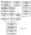
load carrier 1 with anupper deck member 11, alower deck member 12 and a skid 3', and - figure 2 shows a process scheme of the manufacturing process.
- Accordingly, figure 1 shows a load carrier with an upper deck member 11 a
lower deck member 12 and skids 3'. Only parts of theload carrier 1 is shown on order to facilitate understanding of the invention. Parts has furthermore been cut off in order to illustrate the process. The process scheme shows, in steps, the different main events in the manufacturing process. The process is initiated by producing sheet-shaped work pieces 2 by means of an extruder. The sheet-shaped work pieces (not shown) are allowed to cool and post-shrink for about 12 hours. Extended bar sections 3 (not shown) with a mainly rectangular cross-section are also produced by means of an extruder. The bar sections are also allowed to cool and post-shrink for about 12 hours. - An
upper deck member 11 is then produced by first heating and then moulding two of the sheet-shaped work pieces 2 in a first mould. The mould comprises a first and a second mould half, which mould halves comprises each one shaping cavity. The two shaping cavities are together a negative representation of anupper deck member 11 to aload carrier 1. The mould halves are arranged so that an intermediate space is formed between them and that the cavities are facing each other. The two heated work pieces (not shown) are hereby placed in the intermediate space between the two cavities after which they are shaped by one cavity each under influence of vacuum and/or pressure whereupon the mould halves are pressed together while the thermoplastic material is still hot so that the two work pieces are welded with each other and forms a hollow unit. A tube can be inserted between the two layers before they are joined. Compressed air is then injected through the tube once the two layers are joined. It will hereby be possible to more accurately mould the part, especially in sharp corners and transitions. The thermoplastic material is then allowed to cool somewhat before the mould is opened. Theupper deck member 11 is then removed and the process can be repeated. - A
lower deck member 12 is also manufactured by heating and then moulding two further work pieces 2, which after heating is moulded in a second mould. This second mould comprises a first and a second mould half, which mould halves each comprises one shaping cavity. The two cavities are together a negative representation of alower deck member 12 to aload carrier 1. The two heated work pieces are placed, shaped, welded and removed in a manner similar to the manufacturing of theupper deck member 11. It is, of course possible to mould the twodeck members - A skid 3' is furthermore manufactured by first heating and then moulding two of the extended bar sections 3 (not shown) in a third mould. This mould comprises a first and a second mould half. The mould halves includes each one shaping cavity, which cavities together are a negative representation of a skid 3' to a
load carrier 1. The two extendedheated bar sections 3 are placed, moulded and welded in a manner similar to the manufacturing of thedeck members deck members - The
upper deck member 11, thelower deck member 12 and the skid 3' is allowed to cool and post-shrink for 8 hours after being removed from the moulds. - The
upper deck member 11 and thelower deck member 12 are each constituted by upper layers 11' and 12' respectively andlower layer 11" and 12" respectively. - The upper layers 11' and 12' respectively are connected to their respective lower layer via
distance sections 11"' and 12"' respectively. Thedistance sections 11"' and 12"' respectively constitutes an integrated part of therespective layer 11', 11" and 12', 12" respectively and are moulded together with the moulding of therespective layer 11', 11" and 12', 12" respectively. The skid 3' is also provided with distance sections as above according to the enclosed embodiment. - The
deck members areas 10 in connection to the moulding. These are arranged on the lower side of theupper deck member 11, on the upper and lower side of thelower deck member 12 and on the upper side of the skids 3'. The joiningareas 10 are arranged in connection to, or enveloped by mainly vertical surfaces. The risk for a collapse in the different parts during welding are thereby reduced. The joiningareas 10 are of the same reason provided with goods thickness greater than the parts located adjacent to the joiningareas 10. The joiningareas 10 are heated by being pressed against a heated weld core. The different parts are thereafter pressed against each other so that the molten thermoplastic material of the lower joiningarea 10 of theupper deck member 11 and the upper joiningarea 10 of thelower deck member 12 welds with each other and that the lower joiningarea 10 of thelower deck member 12 welds with the upper joiningarea 10 of the skid 3'. The thermoplastic material in the joiningarea 10 is then allowed to cool and solidify, at least somewhat, before the pressing cycle is terminated, whereby a joinednon-reinforced load carrier 1 of thermoplastic material is achieved - The different joining operations may result in that burrs forms along the joining lines of the
load carrier 1. The burrs are suitably removed in one or more operations by means of thermal or mechanical treatment. This operation may become necessary after manufacturing of thedifferent parts - The
load carrier 1 according to the present embodiment is manufactured of a polyolefin, most often polyethylene. The friction coefficient of this material is rather low which may result in problems when using the same. Predetermined surfaces of theload carrier 1 is therefore coated with a friction enhancing material after the assembly. The surfaces that is to be coated are first flame or corona treated and thereafter spray coated with the friction enhancing material. The friction enhancing material is comprises a combination of a polyureaprepolymer and diisocyanate. The surfaces coated are; - the upper side of the
upper deck member 11, - the lower sides of the skids 3' and,
- selected parts of the lower side of the
lower deck member 12. - The invention is not limited to the embodiment shown since it can be varied in different ways within the scope of the invention. Skids 3' may for example be constituted of a massive or hollow extruder profile, which also is illustrated in the process scheme. This alternative manufacturing process for skids 3' is, in the process scheme marked with dashed lines. The step where the skid 3' is vacuum moulded may then be excluded from the process. It may however be necessary to calibrate the outer dimensions of the skid 3' after the post-shrink phase.
- It is also possible to provide the load carrier with a friction enhancing coating earlier in the process. It is, for example, possible to coat the sheet-shaped work pieces 2 as well as the
extended bar sections 3 already after the extrusion. This might prove advantageous as the following treatment may improve the adhesion between the friction coating and the different load carrier parts.
Claims (11)
- Process for the manufacturing of non-reinforced load carriers (1) of thermoplastic material, which process comprises the steps extrusion, vacuum moulding and/or blow moulding work pieces (2) into upper and lower deck members (11 and 12 respectivel y) of a thermoplastic material such as polyethylene, polypropylene or polybutene, which deck members (11 and 12 respectivel y) are allowed to cool and post shrink after which they are welded to form a load carrier (1) characterised in that;a, i) the work pieces (2), in the shape of sheets are manufactured by means of an extruder, which work pieces (2) are allowed to cool and post shrink uniformly after the manufacturing, suitably by an intermediate storing of 6 - 48 hours, and that,a, ii) extended bar sections (3) with a preferably rectangular or polygonal cross-section is manufactured by means of an extruder, which bar sections (3) are allowed to cool and post shrink uniformly after the manufacturing, suitably by an intermediate storing of 6 - 48 hours, whereupon,b, i) the upper deck member (11) is manufactured by heating and then moulding two uniformly post shrinked work pieces (2) in a first mould comprising a first and a second mould half, which mould halves comprises each one shaping cavity, which two shaping cavities together are a negative representation of an upper deck member (11) to a load carrier (1), whereby the mould halves are arranged so that an intermediate space is formed between them and that the cavities are facing each other, whereupon the two heated work pieces (2) are placed in the intermediate space between the two cavities after which they are moulded by one cavity each under influence of vacuum and/or pressure whereupon the mould halves are pressed together while the thermoplastic material is still hot so that the two work pieces are welded with each other and forms a hollow unit whereupon the thermoplastic material is allowed to cool somewhat before the mould is opened, the upper deck member (11) is removed and the process can be repeated, and that,b, ii) the lower deck member (12) is manufactured by heating and then moulding two further, also uniformly post shrinked, work pieces (2), which after heating is formed in a second mould comprising a first and a second mould half, which mould halves each comprises one shaping cavity, which two cavities together is a negative representation of a lower deck member (12) to a load carrier (1), whereby the two heated work pieces are placed, moulded, welded and removed in a manner similar to the manufacturing of the upper deck member (11), and possibly that,b, iii) a skid (3') is manufactured by heating and then forming two of the extended bar sections (3) in a third mould comprising a first and a second mould half comprising a first and a second mould half, which mould halves each comprises one shaping cavity, which two cavities together is a negative representation of a skid (3') to a load carrier (1), whereby the two heated bar sections (3) are placed, moulded, welded and removed in a manner similar to the manufacturing of the deck members (11 and 12 respectively), whereupon,c) the upper and the lower deck member (11 and 12 respectively) are allowed to cool and post shrink uniformly, after being removed from the mould, suitably by an intermediate storing of 6 - 24 hours, whereupon,d) a number of joining surfaces (10) on the lower side of upper deck member (11), on the upper and lower side of the lower deck member (12) and on the upper side of two or three bar sections (3) or alternatively two or three skids (3'), which, in one or more steps, are heated by means of infrared heating, laser or by being pressed against a heated weld core, whereby the different parts, in one or more steps, are pressed together so that the molten thermoplastic material in the lower joining surfaces (10) of the upper deck member (11) and on the upper and lower joining surfaces (10) of the lower deck member (12) as well as the joining surfaces (10) of the bar sections (3) or the skids (3') weld or melt joins, whereby the thermoplastic material in the joining surfaces is allowed to cool and solidify at least partly before the pressing is discontinued,whereby a joined, non-reinforced load carrier (1) of thermoplastic material is achieved.
- A process according to claim 1, characterised in that the thermoplastic material is constituted by a polymer with an average molecular weight in the range 200'000 - 2'000'000 preferably greater than 300'000.
- A process according to claim 1 or 2, characterised in that the deck members (11 and 12 respectively) are provided with mainly vertical surfaces and mainly horizontal surfaces, whereby the joining surfaces (10) are arranged on horizontal surfaces and that vertical surfaces are arranged adjacent to, or envelopes said joining surfaces (10).
- A process according to claim 3, characterised in that the joining surfaces (10) has a goods thickness which is greater than the goods thickness of the sections located adjacent to the joining surfaces (10).
- A process according to any of the claims 1 - 4, characterised in that the bar sections (3), which in the finished load carrier (1) serves as skids (3'), are massive and that these bar sections (3') after cooling and post-shrinking but before joining, are milled to the desired dimension, whereby unwanted cross warping in the finished skid (3') can be avoided.
- A process according to any of the claims 1 - 4, characterised in that the bar sections (3), which in the finished load carrier (1) serves as skids (3'), are hollow extruded profiles and that these bar sections (3), preferably after cooling, post-shrinking and possibly before joining are sealed in both ends by means of plugs or by being thermoformed.
- A process according to any of the claims 1 - 4, characterised in that the upper deck member (11) and the lower deck member (12) each are constituted of an upper layer (11' and 12' respectively) and a lower layer (11" and 12" respectivelly) which upper layers (11' and 12' respectively) are connected with its respective lower layer (11" and 12'' respectively) via distance sections (11''' and 12"' respectively) which distance sections (11''' and 12"' respectively) constitutes an integrated part of the respective layer (11', 11" and 12', 12" respectively) and are moulded in connection to the moulding of the respective layers (11', 11" and 12', 12" respectively).
- A process according to any of the claims 1 - 4, characterised in that the skid (3') is constituted by an upper and a lower layer, which upper layer is connected with the lower layer via distance sections, which distance sections constitutes an integrated part of either or both of the layers and is moulded in connection to the moulding of the respective layers.
- A process according to claim 1, characterised in that the friction coating is performed after the joining of the different parts of the load carrier (1), whereby the parts partly or completely coated are; the upper side of the upper deck member (11), the lower parts of the bar sections (3) and selected parts of the lower side of the lower deck member (12).
- A process according to claim 1, characterised in that the sheet shaped work pieces (2) are oriented so that the direction of extrusion coincides between the layers of the upper and lower deck members (11 and 12 respectively).
- A process according to claim 1, characterised in that the extended bar sections or profiles (3) are oriented so that the direction of extrusion coincides with the different parts the load carrier (1) is made of.
Applications Claiming Priority (3)
| Application Number | Priority Date | Filing Date | Title |
|---|---|---|---|
| SE9804288A SE515539C2 (en) | 1998-12-11 | 1998-12-11 | Process for making non-reinforced thermoplastic carriers |
| SE9804288 | 1998-12-11 | ||
| PCT/SE1999/002124 WO2000035658A1 (en) | 1998-12-11 | 1999-11-19 | A process for the manufacturing of a load carrier |
Publications (3)
| Publication Number | Publication Date |
|---|---|
| EP1137529A1 EP1137529A1 (en) | 2001-10-04 |
| EP1137529B1 EP1137529B1 (en) | 2003-08-06 |
| EP1137529B9 true EP1137529B9 (en) | 2007-10-10 |
Family
ID=20413625
Family Applications (1)
| Application Number | Title | Priority Date | Filing Date |
|---|---|---|---|
| EP99960070A Expired - Lifetime EP1137529B9 (en) | 1998-12-11 | 1999-11-19 | A process for the manufacturing of a load carrier |
Country Status (10)
| Country | Link |
|---|---|
| US (1) | US6676790B1 (en) |
| EP (1) | EP1137529B9 (en) |
| AR (1) | AR021918A1 (en) |
| AT (1) | ATE246587T1 (en) |
| AU (1) | AU1701500A (en) |
| DE (1) | DE69910250T2 (en) |
| ES (1) | ES2205918T3 (en) |
| MY (1) | MY121122A (en) |
| SE (1) | SE515539C2 (en) |
| WO (1) | WO2000035658A1 (en) |
Families Citing this family (4)
| Publication number | Priority date | Publication date | Assignee | Title |
|---|---|---|---|---|
| US7255770B2 (en) * | 2002-08-12 | 2007-08-14 | Mentor Corporation | Method for laser welding flexible polymers |
| KR100985998B1 (en) * | 2009-09-29 | 2010-10-06 | 백대현 | Lightweight pallet |
| WO2011135453A1 (en) * | 2010-04-08 | 2011-11-03 | Magna International Inc. | Shipping pallet post reinforcement |
| DE102015102729A1 (en) * | 2015-02-25 | 2016-08-25 | Schoeller Allibert Gmbh | Lightweight plastic pallet |
Family Cites Families (5)
| Publication number | Priority date | Publication date | Assignee | Title |
|---|---|---|---|---|
| DE2041624A1 (en) | 1970-08-21 | 1972-02-24 | Hollandse Metallurg Ind Billit | Vanadium carbonitride and/or nitride prepn |
| CH562060A5 (en) * | 1973-01-15 | 1975-05-30 | Buehler Ag Geb | |
| US5255613A (en) | 1990-02-26 | 1993-10-26 | Shuert Lyle H | Rackable plastic pallet |
| SE508870C2 (en) * | 1997-03-14 | 1998-11-09 | Perstorp Ab | Manufacture of thermoplastic product e.g. pallets, without reinforcing additives |
| SE508874C2 (en) * | 1997-03-10 | 1998-11-09 | Perstorp Ab | Manufacture of thermoplastic product e.g. pallets, without reinforcing additives |
-
1998
- 1998-12-11 SE SE9804288A patent/SE515539C2/en unknown
-
1999
- 1999-11-19 EP EP99960070A patent/EP1137529B9/en not_active Expired - Lifetime
- 1999-11-19 US US09/857,776 patent/US6676790B1/en not_active Expired - Fee Related
- 1999-11-19 ES ES99960070T patent/ES2205918T3/en not_active Expired - Lifetime
- 1999-11-19 AT AT99960070T patent/ATE246587T1/en not_active IP Right Cessation
- 1999-11-19 WO PCT/SE1999/002124 patent/WO2000035658A1/en active IP Right Grant
- 1999-11-19 DE DE69910250T patent/DE69910250T2/en not_active Expired - Lifetime
- 1999-11-19 AU AU17015/00A patent/AU1701500A/en not_active Abandoned
- 1999-12-09 MY MYPI99005353A patent/MY121122A/en unknown
- 1999-12-20 AR ARP990106569A patent/AR021918A1/en unknown
Also Published As
| Publication number | Publication date |
|---|---|
| SE9804288L (en) | 2000-06-12 |
| ES2205918T3 (en) | 2004-05-01 |
| US6676790B1 (en) | 2004-01-13 |
| WO2000035658A1 (en) | 2000-06-22 |
| ATE246587T1 (en) | 2003-08-15 |
| AU1701500A (en) | 2000-07-03 |
| MY121122A (en) | 2005-12-30 |
| AR021918A1 (en) | 2002-09-04 |
| EP1137529A1 (en) | 2001-10-04 |
| EP1137529B1 (en) | 2003-08-06 |
| SE515539C2 (en) | 2001-08-27 |
| DE69910250D1 (en) | 2003-09-11 |
| SE9804288D0 (en) | 1998-12-11 |
| DE69910250T2 (en) | 2004-06-17 |
Similar Documents
| Publication | Publication Date | Title |
|---|---|---|
| EP0966346B1 (en) | A process for the manufacturing of thermoplastic products with high creep strain resistance | |
| US6294114B1 (en) | Triple sheet thermoforming apparatus, methods and articles | |
| EP1115622B1 (en) | Pallet assembly | |
| EP0754540B1 (en) | Welded plastic panels and method of making same | |
| US6576331B1 (en) | Load-carrying structures comprising bamboo fibers and polymers | |
| JP3859321B2 (en) | Method of welding fiber reinforced resin moldings | |
| EP1137529B9 (en) | A process for the manufacturing of a load carrier | |
| US6651815B1 (en) | Top frame assembly | |
| US20060219354A1 (en) | Method for assembling elements of a structure comprising a honeycomb core | |
| US5181747A (en) | Method for manufacturing a joint and a joint between sections to be joined to each other and surrounded by a joining compound | |
| JPH0455088B2 (en) | ||
| JPS5831285B2 (en) | Seikei Hohou Nikan Surukairiyo | |
| EP0743173B1 (en) | Substantially rigid panel of recyclable composite material and its process of production | |
| SE508874C2 (en) | Manufacture of thermoplastic product e.g. pallets, without reinforcing additives | |
| KR20040085454A (en) | plastic corrugated sheet and the manufacture method | |
| WO2006112781A1 (en) | A thermoplastic product structure for increased creep strain resistance. | |
| TH34675C3 (en) | Process for producing carrier carriers | |
| TH42979A3 (en) | Process for producing carrier carriers | |
| KR19980039781A (en) | Manufacturing method of vehicle fuel tank | |
| AU2887899A (en) | Load-carrying structures comprising bamboo fibers and polymers | |
| JPH02166040A (en) | Synthetic resin box with folded flange and manufacture thereof | |
| AU2008229949A1 (en) | Pallet assembly |
Legal Events
| Date | Code | Title | Description |
|---|---|---|---|
| PUAI | Public reference made under article 153(3) epc to a published international application that has entered the european phase |
Free format text: ORIGINAL CODE: 0009012 |
|
| 17P | Request for examination filed |
Effective date: 20010629 |
|
| AK | Designated contracting states |
Kind code of ref document: A1 Designated state(s): AT BE CH CY DE DK ES FI FR GB GR IE IT LI LU MC NL PT SE |
|
| 17Q | First examination report despatched |
Effective date: 20020610 |
|
| GRAH | Despatch of communication of intention to grant a patent |
Free format text: ORIGINAL CODE: EPIDOS IGRA |
|
| GRAH | Despatch of communication of intention to grant a patent |
Free format text: ORIGINAL CODE: EPIDOS IGRA |
|
| GRAA | (expected) grant |
Free format text: ORIGINAL CODE: 0009210 |
|
| RAP1 | Party data changed (applicant data changed or rights of an application transferred) |
Owner name: ARCA SYSTEMS AB |
|
| AK | Designated contracting states |
Designated state(s): AT BE CH CY DE DK ES FI FR GB GR IE IT LI LU MC NL PT SE |
|
| PG25 | Lapsed in a contracting state [announced via postgrant information from national office to epo] |
Ref country code: LI Free format text: LAPSE BECAUSE OF FAILURE TO SUBMIT A TRANSLATION OF THE DESCRIPTION OR TO PAY THE FEE WITHIN THE PRESCRIBED TIME-LIMIT Effective date: 20030806 Ref country code: FI Free format text: LAPSE BECAUSE OF FAILURE TO SUBMIT A TRANSLATION OF THE DESCRIPTION OR TO PAY THE FEE WITHIN THE PRESCRIBED TIME-LIMIT Effective date: 20030806 Ref country code: CH Free format text: LAPSE BECAUSE OF FAILURE TO SUBMIT A TRANSLATION OF THE DESCRIPTION OR TO PAY THE FEE WITHIN THE PRESCRIBED TIME-LIMIT Effective date: 20030806 Ref country code: AT Free format text: LAPSE BECAUSE OF FAILURE TO SUBMIT A TRANSLATION OF THE DESCRIPTION OR TO PAY THE FEE WITHIN THE PRESCRIBED TIME-LIMIT Effective date: 20030806 |
|
| REG | Reference to a national code |
Ref country code: GB Ref legal event code: FG4D |
|
| REG | Reference to a national code |
Ref country code: CH Ref legal event code: EP |
|
| REG | Reference to a national code |
Ref country code: IE Ref legal event code: FG4D |
|
| REF | Corresponds to: |
Ref document number: 69910250 Country of ref document: DE Date of ref document: 20030911 Kind code of ref document: P |
|
| PG25 | Lapsed in a contracting state [announced via postgrant information from national office to epo] |
Ref country code: SE Free format text: LAPSE BECAUSE OF FAILURE TO SUBMIT A TRANSLATION OF THE DESCRIPTION OR TO PAY THE FEE WITHIN THE PRESCRIBED TIME-LIMIT Effective date: 20031106 Ref country code: GR Free format text: LAPSE BECAUSE OF FAILURE TO SUBMIT A TRANSLATION OF THE DESCRIPTION OR TO PAY THE FEE WITHIN THE PRESCRIBED TIME-LIMIT Effective date: 20031106 Ref country code: DK Free format text: LAPSE BECAUSE OF FAILURE TO SUBMIT A TRANSLATION OF THE DESCRIPTION OR TO PAY THE FEE WITHIN THE PRESCRIBED TIME-LIMIT Effective date: 20031106 |
|
| PG25 | Lapsed in a contracting state [announced via postgrant information from national office to epo] |
Ref country code: LU Free format text: LAPSE BECAUSE OF NON-PAYMENT OF DUE FEES Effective date: 20031119 Ref country code: IE Free format text: LAPSE BECAUSE OF NON-PAYMENT OF DUE FEES Effective date: 20031119 Ref country code: CY Free format text: LAPSE BECAUSE OF FAILURE TO SUBMIT A TRANSLATION OF THE DESCRIPTION OR TO PAY THE FEE WITHIN THE PRESCRIBED TIME-LIMIT Effective date: 20031119 |
|
| PG25 | Lapsed in a contracting state [announced via postgrant information from national office to epo] |
Ref country code: MC Free format text: LAPSE BECAUSE OF NON-PAYMENT OF DUE FEES Effective date: 20031130 |
|
| PG25 | Lapsed in a contracting state [announced via postgrant information from national office to epo] |
Ref country code: PT Free format text: LAPSE BECAUSE OF FAILURE TO SUBMIT A TRANSLATION OF THE DESCRIPTION OR TO PAY THE FEE WITHIN THE PRESCRIBED TIME-LIMIT Effective date: 20040106 |
|
| REG | Reference to a national code |
Ref country code: CH Ref legal event code: PL |
|
| REG | Reference to a national code |
Ref country code: ES Ref legal event code: FG2A Ref document number: 2205918 Country of ref document: ES Kind code of ref document: T3 |
|
| ET | Fr: translation filed | ||
| PLBE | No opposition filed within time limit |
Free format text: ORIGINAL CODE: 0009261 |
|
| STAA | Information on the status of an ep patent application or granted ep patent |
Free format text: STATUS: NO OPPOSITION FILED WITHIN TIME LIMIT |
|
| 26N | No opposition filed |
Effective date: 20040507 |
|
| REG | Reference to a national code |
Ref country code: IE Ref legal event code: MM4A |
|
| NLT1 | Nl: modifications of names registered in virtue of documents presented to the patent office pursuant to art. 16 a, paragraph 1 |
Owner name: SCHOELLER ARCA SYSTEMS AB |
|
| REG | Reference to a national code |
Ref country code: FR Ref legal event code: CD |
|
| PGFP | Annual fee paid to national office [announced via postgrant information from national office to epo] |
Ref country code: IT Payment date: 20101127 Year of fee payment: 12 Ref country code: GB Payment date: 20101130 Year of fee payment: 12 |
|
| PGFP | Annual fee paid to national office [announced via postgrant information from national office to epo] |
Ref country code: ES Payment date: 20111122 Year of fee payment: 13 Ref country code: FR Payment date: 20120106 Year of fee payment: 13 |
|
| PGFP | Annual fee paid to national office [announced via postgrant information from national office to epo] |
Ref country code: DE Payment date: 20121126 Year of fee payment: 14 |
|
| PGFP | Annual fee paid to national office [announced via postgrant information from national office to epo] |
Ref country code: BE Payment date: 20121129 Year of fee payment: 14 |
|
| PGFP | Annual fee paid to national office [announced via postgrant information from national office to epo] |
Ref country code: NL Payment date: 20121122 Year of fee payment: 14 |
|
| GBPC | Gb: european patent ceased through non-payment of renewal fee |
Effective date: 20121119 |
|
| REG | Reference to a national code |
Ref country code: FR Ref legal event code: ST Effective date: 20130731 |
|
| PG25 | Lapsed in a contracting state [announced via postgrant information from national office to epo] |
Ref country code: IT Free format text: LAPSE BECAUSE OF NON-PAYMENT OF DUE FEES Effective date: 20121119 |
|
| PG25 | Lapsed in a contracting state [announced via postgrant information from national office to epo] |
Ref country code: FR Free format text: LAPSE BECAUSE OF NON-PAYMENT OF DUE FEES Effective date: 20121130 Ref country code: GB Free format text: LAPSE BECAUSE OF NON-PAYMENT OF DUE FEES Effective date: 20121119 |
|
| REG | Reference to a national code |
Ref country code: ES Ref legal event code: FD2A Effective date: 20140305 |
|
| PG25 | Lapsed in a contracting state [announced via postgrant information from national office to epo] |
Ref country code: ES Free format text: LAPSE BECAUSE OF NON-PAYMENT OF DUE FEES Effective date: 20121120 |
|
| BERE | Be: lapsed |
Owner name: SCHOELLER ARCA SYSTEMS A.B. Effective date: 20131130 |
|
| REG | Reference to a national code |
Ref country code: NL Ref legal event code: V1 Effective date: 20140601 |
|
| REG | Reference to a national code |
Ref country code: DE Ref legal event code: R119 Ref document number: 69910250 Country of ref document: DE Effective date: 20140603 |
|
| PG25 | Lapsed in a contracting state [announced via postgrant information from national office to epo] |
Ref country code: DE Free format text: LAPSE BECAUSE OF NON-PAYMENT OF DUE FEES Effective date: 20140603 Ref country code: NL Free format text: LAPSE BECAUSE OF NON-PAYMENT OF DUE FEES Effective date: 20140601 |
|
| PG25 | Lapsed in a contracting state [announced via postgrant information from national office to epo] |
Ref country code: BE Free format text: LAPSE BECAUSE OF NON-PAYMENT OF DUE FEES Effective date: 20131130 |