EP1137145A2 - Anti-reverse connection circuit for power supply - Google Patents
Anti-reverse connection circuit for power supply Download PDFInfo
- Publication number
- EP1137145A2 EP1137145A2 EP01106605A EP01106605A EP1137145A2 EP 1137145 A2 EP1137145 A2 EP 1137145A2 EP 01106605 A EP01106605 A EP 01106605A EP 01106605 A EP01106605 A EP 01106605A EP 1137145 A2 EP1137145 A2 EP 1137145A2
- Authority
- EP
- European Patent Office
- Prior art keywords
- input terminal
- switch transistor
- power supply
- load
- emitter
- Prior art date
- Legal status (The legal status is an assumption and is not a legal conclusion. Google has not performed a legal analysis and makes no representation as to the accuracy of the status listed.)
- Withdrawn
Links
Images

Classifications
-
- H—ELECTRICITY
- H02—GENERATION; CONVERSION OR DISTRIBUTION OF ELECTRIC POWER
- H02H—EMERGENCY PROTECTIVE CIRCUIT ARRANGEMENTS
- H02H11/00—Emergency protective circuit arrangements for preventing the switching-on in case an undesired electric working condition might result
- H02H11/002—Emergency protective circuit arrangements for preventing the switching-on in case an undesired electric working condition might result in case of inverted polarity or connection; with switching for obtaining correct connection
-
- H—ELECTRICITY
- H02—GENERATION; CONVERSION OR DISTRIBUTION OF ELECTRIC POWER
- H02H—EMERGENCY PROTECTIVE CIRCUIT ARRANGEMENTS
- H02H11/00—Emergency protective circuit arrangements for preventing the switching-on in case an undesired electric working condition might result
-
- H—ELECTRICITY
- H02—GENERATION; CONVERSION OR DISTRIBUTION OF ELECTRIC POWER
- H02H—EMERGENCY PROTECTIVE CIRCUIT ARRANGEMENTS
- H02H11/00—Emergency protective circuit arrangements for preventing the switching-on in case an undesired electric working condition might result
- H02H11/006—Emergency protective circuit arrangements for preventing the switching-on in case an undesired electric working condition might result in case of too high or too low voltage
Definitions
- the present invention relates to an anti-reverse connection circuit for a power supply, and particularly to an anti-reverse connection circuit for a power supply, which prevents a reverse voltage from being applied to a load such as a control circuit for fit-up equipment activated by in-vehicle electricity, due to a reverse connection of an external power supply such as a battery to the load.
- the power-supply anti-reverse connection circuit comprises an input terminal 11 connected to a positive polarity of an external power supply (BATT), an input terminal 12 connected to a negative polarity of the external power supply, load terminals 13 and 14 to which a load is connected, and a rectifier cell or device (e.g., diode) 15.
- BATT external power supply
- the rectifier cell or device e.g., diode
- the diode 15 is placed between the input terminal 11 and the load terminal 13.
- the anode of the diode 15 is connected to the input terminal 11, and the cathode thereof is connected to the load terminal 13. Further, the input terminal 12 and the load terminal 14 are directly connected to each other.
- the diode 15 When the external power supply is correctly connected in such a configuration, i.e., when a positive-polarity voltage (e.g., + 12V) is applied to the input terminal 11 from the external power supply and a negative-polarity voltage (e.g., 0V) is applied to the input terminal 12, the diode 15 is brought to a conducting state, so that the voltage supplied from the external power supply is applied between the load terminals 13 and 14 through the diode 15, The voltage applied at this time results in a voltage obtained by subtracting a voltage drop (which ranges from 0.6V to 0.7V) developed across the diode 15 from the voltage supplied from the external power supply.
- a positive-polarity voltage e.g., + 12V
- a negative-polarity voltage e.g., 0V
- the diode 15 When the external power supply is connected in the backward direction, i.e., when the negative-polarity voltage (e.g., 0V) is applied to the input terminal 11 and the positive-polarity voltage (e.g., + 12V) is applied to the input terminal 12, the diode 15 is brought to a nonconducting state, so that a current flowing between the input terminal 11 and the load terminal 13 is cut off. Thus, no voltage is applied between the load terminals 13 and 14.
- the negative-polarity voltage e.g., 0V
- the positive-polarity voltage e.g., + 12V
- the conventional power-supply anti-reverse connection circuit has used rectifying action of the diode to prevent the application of a reverse voltage to a load when the external power supply is connected in the backward direction.
- An object of the present invention is to provide a power-supply anti-reverse connection circuit which prevents a reduction in the voltage applied to a load and eliminates the need for a layout with respect to radiation even if current consumption of the load increases, and which avoids an increase in price.
- the present invention comprises a first input terminal to be connected to a positive polarity of an external power supply, a second input terminal to be connected to a negative polarity of the external power supply, a first load terminal to which one end of a load is connected, a second load terminal to which the other end of the load is connected, a relay having a normally opened contact and an excitation coil, and a control circuit for allowing a current to flow in the excitation coil. Either one of both the first input terminal and the first load terminal, and the second input terminal and the second load terminal is connected to each other via the normally opened contact and the other thereof is directly connected to each other.
- the control circuit causes the current to flow in the excitation coil only when the positive polarity is connected to the first input terminal and the negative polarity is connected to the second input terminal.
- the control circuit inhibits the flow of the current in the excitation coil.
- the control circuit has a resistance-based voltage divider circuit connected between the first input terminal and the second input terminal, and a first switch transistor.
- the collector and emitter of the first switch transistor are respectively connected to the first input terminal and the second input terminal in such a manner that a current flows from the first input terminal to the second input terminal through the collector and emitter of the first switch transistor when the first switch transistor is turned on.
- the excitation coil is interposed in a passage through which the current flows. A voltage divided by the voltage divider circuit is applied to the base of the first switch transistor.
- the control circuit includes a zener diode whose cathode is connected to the first input terminal, a bias resistor connected between the anode of the zener diode and the second input terminal, and an NPN type second switch transistor of which the collector is connected to the first input terminal and the emitter is connected to the second input terminal.
- the base of the second switch transistor is connected to a point where the zener diode and the bias resistor are connected to each other.
- the excitation coil is interposed either between the collector of the second switch transistor and the first input terminal or between the emitter of the second switch transistor and the second input terminal.
- the control circuit includes a zener diode whose anode is connected to the second input terminal, a bias resistor connected between the cathode of the zener diode and the first input terminal, and a PNP type third switch transistor whose collector is connected to the second input terminal and whose emitter is connected to the first input terminal.
- the base of the third switch transistor is connected to a point where the zener diode and the bias resistor are connected to each other.
- the excitation coil is interposed either between the collector of the third switch transistor and the second input terminal or between the emitter of the third switch transistor and the first input terminal.
- the first switch transistor is an NPN type.
- a capacitor for noise elimination is connected between the base of the first switch transistor and the second input terminal.
- An anti-reverse current diode is interposed in a passage through which a current flows from the first input terminal to the second input terminal through the collector and emitter of the first switch transistor when the first switch transistor is turned on.
- the first switch transistor is a PNP type.
- a capacitor for noise elimination is connected between the base of the first switch transistor and the first input terminal.
- An anti-reverse current diode is interposed in a passage through which a current flows from the first input terminal to the second input terminal through the collector and emitter of the first switch transistor when the first switch transistor is turned on.
- a capacitor for noise elimination is connected between the base of the second switch transistor and the second input terminal.
- An anti-reverse current diode is interposed in a passage through which a current flows from the first input terminal to the second input terminal through the collector and emitter of the second switch transistor when the second switch transistor is turned on.
- a capacitor for noise elimination is connected between the base of the third switch transistor and the first input terminal.
- An anti-reverse current diode is interposed in a passage through which a current flows from the first input terminal to the second input terminal through the collector and emitter of the third switch transistor when the third switch transistor is turned on.
- Fig. 1 is a circuit diagram showing a first embodiment of a power-supply anti-reverse connection circuit of the present invention.
- Fig. 2 is a circuit diagram illustrating a second embodiment of a power-supply anti-reverse connection circuit of the present invention.
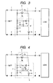
- Fig. 3 is a circuit diagram depicting a third embodiment of a power-supply anti-reverse connection circuit of the present invention.
- Fig. 4 is another circuit diagram showing another embodiment of a power-supply anti-reverse connection circuit of the present invention.
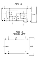
- Fig. 5 is a further circuit diagram illustrating a further embodiment of a power-supply anti-reverse connection circuit of the present invention.
- Fig. 6 is a circuit diagram showing an embodiment of a conventional power-supply anti-reverse connection circuit.
- Fig. 1 is a circuit diagram showing a first embodiment of a power-supply anti-reverse connection or reverse-connection prevention circuit of the present invention.
- the first embodiment comprises a first input terminal 1 connected to the positive polarity of an external power or power supply (BATT), a second input terminal 2 connected to the negative polarity of the external power supply, a first load terminal 3 to which one end of a load is connected, a second load terminal 4 to which the other end of the load is connected, a relay 5 having a normally opened contact 5a and an excitation coil 5b, and a control circuit 6 for causing a current to flow in the excitation coil 5b.
- the relay 5 makes use of a small and inexpensive one.
- the input terminal 1 and the load terminal 3 are connected to each other through the normally opened contact 5a.
- the input terminal 2 and the load terminal 4 are directly connected to each other.
- the control circuit 6 includes a voltage dividing or divider circuit 7 having bias resistors 7a and 7b connected between the input terminal 1 and the input terminal 2, and a first switch transistor 6a. Further, the collector of the switch transistor 6a is connected to the input terminal 1 through the excitation coil 5b, and the emitter thereof is connected to its corresponding anode of an anti-reverse current diode 6c. The cathode of the diode 6c is connected to the input terminal 2. Further, the base of the switch transistor 6a is connected to a point where the bias resistors 7a and 7b are connected, and connected to the input terminal 2 through a capacitor 6b for noise elimination.
- the excitation coil 5b and the diode 6c exist within a channel or passage of a current which flows from the input terminal 1 to the input terminal 2 through the collector and emitter of the switch transistor 6a, then they are identical in function to each other even if they are located in any place.
- the normally opened contact 5a of the relay 5 is closed so that the voltage (12V) from the external power supply is applied between the load terminals 3 and 4.
- the diode 6c serves so as to prevent the flow of a reverse current in the switch transistor 6a
- the capacitor 6b serves as a filter capacitor which prevents a malfunction of the switch transistor 6a when an abnormal or improper voltage (transient voltage, surge voltage) is applied to the input terminal 1.
- a diode 6d connected in parallel with the excitation coil 5b is used for absorbing and eliminating a back electromotive voltage developed upon turning on/off of the excitation coil 5b.
- the relay 5 is used in place of the rectifier cell or device 15 employed in the conventional example, no heat is generated even if the current used up or consumed by a load increases, and no voltage drop is developed between the voltages supplied from the external power supply and the load terminals 3 and 4. Accordingly, the efficiency is not reduced. Further, an increase in cost is not produced either.
- Fig. 2 is a circuit diagram showing a second embodiment of a power-supply anti-reverse connection circuit of the present invention.
- the same elements of structure as those shown in Fig. 1 illustrative of the first embodiment are identified by the same reference numerals as those shown in Fig. 1 and their detailed description will therefore be omitted.
- a control circuit 6 has an NPN type second switch transistor 6e corresponding to the switch transistor 6a employed in the first embodiment.
- a circuit equivalent to the voltage divider circuit 7 employed in the first embodiment comprises a zener diode 8 whose cathode is connected to a first input terminal 1, and a resistor 10 used to prevent the breakdown of the zener diode 8, which is connected between the anode of the zener diode 8 and the base of the switch transistor 6e.
- a zener voltage of the zener diode 8 is set to a minimum value, e.g., 7V lying in a voltage range for normally activating a load.
- the switch transistor 6e is not turned on unless a voltage greater than the zener voltage of the zener diode 7c is applied between the input terminals 1 and 2. Consequently, since no voltage is applied across the load when the voltage to be.supplied from the external power supply is low (less than or equal to 7V), a failure in load, a malfunction thereof, the shortening of life of the external power supply, etc. can be prevented from occurring.
- Fig. 3 is a circuit diagram showing a third embodiment of a power-supply anti-reverse connection circuit of the present invention.
- the same elements of structure as those shown in Fig. 2 illustrative of the second embodiment are identified by the same reference numerals and their detailed description will therefore be omitted.
- a control circuit 6 has a PNP type third switch transistor 6f equivalent to the switch transistor 6e employed in the second embodiment.
- the anode of a zener diode 8 whose cathode is connected to the base of the switch transistor 6f, is connected to an input terminal 2 through a resistor 10 for the prevention of breakdown.
- a bias resistor 9 is connected between an input terminal 1 and the base of the switch transistor 6f.
- a capacitor 6b for noise elimination is connected between the input terminal 1 and the base of the switch transistor 6f.
- Fig. 4 is a circuit diagram showing another embodiment of a power-supply anti-reverse connection circuit of the present invention.
- the same elements of structure as those shown in Fig. 1 illustrative of the first embodiment are identified by the same reference numeral as those shown in Fig. 1 and their detailed description will therefore be omitted.
- a control circuit 6 has a PNP type fourth switch transistor 6g corresponding to the switch transistor 6a employed in the first embodiment.
- a capacitor 6b for noise elimination is connected between an input terminal 1 and the base of the switch transistor 6g.
- Fig. 5 is a circuit diagram showing a further embodiment of a power-supply anti-reverse connection circuit of the present invention.
- the power-supply anti-reverse connection circuit is one wherein the normally opened contact 5a employed in the second embodiment is provided between an input terminal 2 and a load terminal 4. Since the present power-supply anti-reverse connection circuit is similar to the second embodiment in configuration and operation, their description will be omitted.
- the object of the present invention can be achieved even if such a configuration that a normally closed contact is adopted and opened only when it is always in a conducting state and a reverse voltage is applied, thereby blocking or cutting off the power supply, is adopted.
- the normally closed contact serves so as to apply the reverse voltage to a load during a period (generally a few milli-seconds) from the application of the reverse voltage to the time when an excitation coil of a relay is energized to activate and open the normally closed contact.
- the configuration of the load is a semiconductor or the like, it might deviate from the absolute maximum rating of the semiconductor for a few milli-seconds.
- the normally opened contact is provided, no reverse voltage is applied to the load even in a moment, and the risk of the breakdown of the aforementioned circuit (or IC) can reliably be avoided.
Landscapes
- Direct Current Feeding And Distribution (AREA)
- Charge And Discharge Circuits For Batteries Or The Like (AREA)
- Relay Circuits (AREA)
- Control Of Voltage And Current In General (AREA)
Abstract
Description
Claims (9)
- An anti-reverse connection circuit for an external power supply, comprising:a first input terminal to be connected to a positive polarity of the external power supply;a second input terminal to be connected to a negative polarity of the external power supply;a first load terminal to which one end of a load is connected;a second load terminal to which the other end of the load is connected;a relay having a normally opened contact and an excitation coil; anda control circuit for allowing a current to flow in the excitation coil,wherein either one of both the first input terminal and the first load terminal, or the second input terminal and the second load terminal is connected to each other via the normally opened contact and the other thereof is directly connected to each other, andthe control circuit causes the current to flow in the excitation coil only when the positive polarity is connected to the first input terminal and the negative polarity is connected to the second input terminal.
- The anti-reverse connection circuit for the power supply according to claim 1, wherein when the voltage supplied from the external power supply is lower than a predetermined voltage, the control circuit inhibits the flow of the current in the excitation coil.
- The anti-reverse connection circuit for the power supply according to claim 1 or 2, wherein the control circuit has a voltage divider circuit connected between the first input terminal and the second input terminal, and a first switch transistor,the collector and emitter of the first switch transistor are respectively connected to the first input terminal and the second input terminal in such a manner that a current flows from the first input terminal to the second input terminal through the collector and emitter of the first switch transistor when the first switch transistor is turned on,the excitation coil is interposed in a passage through which the current flows, anda voltage divided by the voltage divider circuit is applied to the base of the first switch transistor.
- The anti-reverse connection circuit for the power supply according to any one of claims 1 to 3, wherein the control circuit includes a zener diode whose cathode is connected to the first input terminal;a bias resistor connected between the anode of the zener diode and the second input terminal, andan NPN type second switch transistor of which the collector is connected to the first input terminal and the emitter is connected to the second input terminal, andthe base of the second switch transistor is connected to a point where the zener diode and the bias resistor are connected to each other, andthe excitation coil is interposed either between the collector of the second switch transistor and the first input terminal or between the emitter of the second switch transistor and the second input terminal.
- The anti-reverse connection circuit for the power supply according to any one of claims 1 to 3, wherein the control circuit includes a zener diode whose anode is connected to the second input terminal,a bias resistor connected between the cathode of the zener diode and the first input terminal, anda PNP type third switch transistor whose collector is connected to the second input terminal and whose emitter is connected to the first input terminal, andthe base of the third switch transistor is connected to a point where the zener diode and the bias resistor are connected to each other, andthe excitation coil is interposed either between the collector of the third switch transistor and the second input terminal or between the emitter of the third switch transistor and the first input terminal.
- The anti-reverse connection circuit for the power supply according to claim 3 or 4, wherein the first switch transistor is an NPN type,a capacitor for noise elimination is connected between the base of the first switch transistor and the second input terminal, andan anti-reverse current diode is interposed in a passage through which a current flows from the first input terminal to the second input terminal through the collector and emitter of the first switch transistor when the first switch transistor is turned on.
- The anti-reverse connection circuit for the power supply according to claim 3, wherein the first switch transistor is a PNP type,a capacitor for noise elimination is connected between the base of the first switch transistor and the first input terminal, andan anti-reverse current diode is interposed in a passage through which a current flows from the first input terminal to the second input terminal through the collector and emitter of the first switch transistor when the first switch transistor is turned on.
- The anti-reverse connection circuit for the power supply according to claim 4, wherein a capacitor for noise elimination is connected between the base of the second switch transistor and the second input terminal, and
an anti-reverse current diode is interposed in a passage through which a current flows from the first input terminal to the second input terminal through the collector and emitter of the second switch transistor when the second switch transistor is turned on. - The anti-reverse connection circuit for the power supply according to claim 5, wherein a capacitor for noise elimination is connected between the base of the third switch transistor and the first input terminal, and
an anti-reverse current diode is interposed in a passage through which a current flows from the first input terminal to the second input terminal through the collector and emitter of the third switch transistor when the third switch transistor is turned on.
Applications Claiming Priority (2)
| Application Number | Priority Date | Filing Date | Title |
|---|---|---|---|
| JP2000081861A JP2001268784A (en) | 2000-03-17 | 2000-03-17 | Inverse connection preventing circuit of power source |
| JP2000081861 | 2000-03-17 |
Publications (2)
| Publication Number | Publication Date |
|---|---|
| EP1137145A2 true EP1137145A2 (en) | 2001-09-26 |
| EP1137145A3 EP1137145A3 (en) | 2005-10-05 |
Family
ID=18598732
Family Applications (1)
| Application Number | Title | Priority Date | Filing Date |
|---|---|---|---|
| EP20010106605 Withdrawn EP1137145A3 (en) | 2000-03-17 | 2001-03-15 | Anti-reverse connection circuit for power supply |
Country Status (4)
| Country | Link |
|---|---|
| US (1) | US6519126B2 (en) |
| EP (1) | EP1137145A3 (en) |
| JP (1) | JP2001268784A (en) |
| KR (1) | KR100398692B1 (en) |
Cited By (10)
| Publication number | Priority date | Publication date | Assignee | Title |
|---|---|---|---|---|
| CN102545198A (en) * | 2010-12-29 | 2012-07-04 | 广东易事特电源股份有限公司 | An anti-reverse connection protection circuit for a solar charge controller with a common anode structure |
| CN103001177A (en) * | 2011-09-19 | 2013-03-27 | 海洋王(东莞)照明科技有限公司 | LED lamp and overheat protecting circuit thereof |
| WO2013081189A1 (en) * | 2011-12-01 | 2013-06-06 | Yazaki Corporation | Relay device |
| CN103346552A (en) * | 2013-06-25 | 2013-10-09 | 西安电子科技大学 | Reverse connection prevention circuit |
| CN103855681A (en) * | 2012-11-30 | 2014-06-11 | 深圳市海洋王照明工程有限公司 | Lamp open circuit protective circuit |
| EP2363936B1 (en) * | 2010-02-27 | 2015-05-27 | Byd Company Limited | Reverse connection protecting device and backup power supply comprising the same |
| CN105430801A (en) * | 2015-12-20 | 2016-03-23 | 合肥艾斯克光电科技有限责任公司 | LED over-current protection circuit |
| CN108123496A (en) * | 2016-11-30 | 2018-06-05 | 武汉通畅汽车电子照明有限公司 | A kind of binary channels supplies electric installation and electronic equipment |
| CN109217242A (en) * | 2018-11-08 | 2019-01-15 | 上海艾为电子技术股份有限公司 | A kind of power-switching circuit with counnter attack connection function, integrated circuit |
| CN114978139A (en) * | 2022-07-19 | 2022-08-30 | 长沙电力设计院有限公司 | A kind of anti-reverse connection low-side control circuit |
Families Citing this family (28)
| Publication number | Priority date | Publication date | Assignee | Title |
|---|---|---|---|---|
| DE10040879A1 (en) * | 2000-08-18 | 2002-02-28 | Thomson Brandt Gmbh | Power adapter with a battery |
| US6825577B2 (en) * | 2001-12-10 | 2004-11-30 | Fluke Corporation | Dual power polarity protector/indicator |
| FI118024B (en) * | 2001-12-17 | 2007-05-31 | Tellabs Oy | Polarity protection by MOSFET |
| US6969971B2 (en) * | 2002-12-05 | 2005-11-29 | International Rectifier Corporation | Reverse battery protection circuit |
| KR100752738B1 (en) * | 2006-02-09 | 2007-08-28 | 한국알프스 주식회사 | Power supply circuit |
| US20080247108A1 (en) * | 2007-04-03 | 2008-10-09 | Denso Corporation | Load drive device |
| US8193881B2 (en) * | 2007-09-14 | 2012-06-05 | Fujitsu Component Limited | Relay |
| TWI355126B (en) * | 2007-11-30 | 2011-12-21 | Altek Corp | Protect circuit of car power |
| CN101592697B (en) * | 2009-06-02 | 2011-04-06 | 上海广为电器工具有限公司 | Polarity intelligent recognition device |
| KR101046476B1 (en) * | 2010-05-03 | 2011-07-04 | 김정호 | Luminaire Control |
| EP2498369B1 (en) * | 2011-06-08 | 2015-03-25 | Huawei Technologies Co., Ltd. | Control circuit for preventing battery group from being reversely connected and power supply system for base station |
| CN102892221B (en) * | 2011-07-20 | 2015-04-29 | 海洋王照明科技股份有限公司 | LED (light-emitted diode) lamp and open-circuit protective circuit thereof |
| CN103001179B (en) * | 2011-09-08 | 2016-03-30 | 海洋王照明科技股份有限公司 | A kind of LED lamp and short-circuit protection circuit thereof |
| CN103024973B (en) * | 2011-09-23 | 2015-04-01 | 海洋王(东莞)照明科技有限公司 | LED (Light-Emitting Diode) lamp and overcurrent protection circuit thereof |
| CN103391660A (en) * | 2012-05-09 | 2013-11-13 | 海洋王(东莞)照明科技有限公司 | LED lamp over-temperature protection circuit and LED lamp |
| CN103795051B (en) * | 2012-11-01 | 2017-12-15 | 海洋王(东莞)照明科技有限公司 | A kind of overvoltage crowbar and light fixture |
| CN103208793B (en) * | 2013-04-17 | 2016-08-10 | 大连尚能科技发展有限公司 | Anti-reverse connection circuit of direct current power supply |
| CN104617773A (en) * | 2013-11-04 | 2015-05-13 | 深圳市海洋王照明工程有限公司 | Positive-negative automatic conversion circuit and power output module |
| CN105552877A (en) * | 2016-02-01 | 2016-05-04 | 凯迈(洛阳)电子有限公司 | Reverse connection monitoring device of power storage battery |
| CN106100027A (en) * | 2016-06-27 | 2016-11-09 | 深圳天珑无线科技有限公司 | Charger and the short-circuit protection circuit for charging inlet |
| CN108565836B (en) * | 2018-01-17 | 2024-05-07 | 宁波高发汽车控制系统股份有限公司 | Reverse connection preventing circuit for automobile motor power supply |
| CN111342441B (en) * | 2018-12-18 | 2022-12-06 | 华为数字能源技术有限公司 | A kind of DC/DC conversion circuit |
| CN110224617B (en) * | 2019-07-08 | 2024-03-29 | 维尔纳集电电子科技(福建)有限公司 | Reverse connection preventing silicon controlled rectifier circuit |
| CN111615247A (en) * | 2020-05-13 | 2020-09-01 | 迅驰车业江苏有限公司 | A kind of automobile drive front-end PMOS anti-backflow circuit |
| CN113725845A (en) * | 2020-05-25 | 2021-11-30 | 南宁富桂精密工业有限公司 | DC power supply circuit |
| CN115474314B (en) * | 2022-10-31 | 2023-03-24 | 广东东菱电源科技有限公司 | High-voltage-resistant reverse-connection-prevention LED dimming interface protection circuit |
| US12476461B2 (en) | 2022-12-01 | 2025-11-18 | Portable Electric Ltd. | Circuits for photovoltaic applications |
| CN118137444B (en) * | 2024-05-06 | 2024-07-05 | 深圳市积加创新技术有限公司 | Circuit capable of normally working through positive and negative connection and inverse connection of direct-current power supply |
Family Cites Families (14)
| Publication number | Priority date | Publication date | Assignee | Title |
|---|---|---|---|---|
| US4027233A (en) * | 1973-07-23 | 1977-05-31 | Eduard Ivanovich Shmakov | Contactless inductance pickup for detecting the interface of two media |
| ATE65863T1 (en) * | 1986-09-11 | 1991-08-15 | Siemens Ag | REVERSE POLARITY AND AC VOLTAGE PROTECTION FOR DIRECT CURRENT OPERATED ELECTRICAL CONSUMERS. |
| JPH05219649A (en) * | 1992-02-03 | 1993-08-27 | Nippon Denki Musen Denshi Kk | Power supply switching circuit |
| US5519557A (en) * | 1993-11-19 | 1996-05-21 | Chrysler Corporation | Power supply polarity reversal protection circuit |
| JPH07322488A (en) * | 1994-05-30 | 1995-12-08 | Nec Corp | Power supply protection circuit |
| FR2722348B1 (en) * | 1994-07-11 | 1996-10-11 | Aerospatiale | ELECTRONIC CONNECTION DEVICE WITH POLARITY INVERSION PROTECTION |
| JPH09200951A (en) * | 1996-01-12 | 1997-07-31 | Canon Inc | Battery device |
| DE19702116C2 (en) * | 1997-01-22 | 1999-02-18 | Siemens Ag | Protection against incorrect polarity in the electrical system of a vehicle |
| DE19719919A1 (en) * | 1997-05-13 | 1998-11-26 | Daimler Benz Ag | Arrangement for the protection of electrical equipment |
| JPH10336905A (en) | 1997-06-02 | 1998-12-18 | Harness Sogo Gijutsu Kenkyusho:Kk | Battery reverse connection protection device |
| KR19990051913A (en) * | 1997-12-20 | 1999-07-05 | 홍종만 | Alternator Protection Circuit |
| JP3815885B2 (en) * | 1998-04-28 | 2006-08-30 | 日本電産株式会社 | Pump device |
| DE29824874U1 (en) * | 1998-07-10 | 2003-04-30 | Ellenberger & Poensgen GmbH, 90518 Altdorf | Circuit-breaker device |
| US6262492B1 (en) * | 1999-04-09 | 2001-07-17 | Dhc Specialty Corp. | Car battery jumper cable |
-
2000
- 2000-03-17 JP JP2000081861A patent/JP2001268784A/en not_active Withdrawn
-
2001
- 2001-03-14 US US09/808,336 patent/US6519126B2/en not_active Expired - Lifetime
- 2001-03-15 EP EP20010106605 patent/EP1137145A3/en not_active Withdrawn
- 2001-03-16 KR KR10-2001-0013624A patent/KR100398692B1/en not_active Expired - Fee Related
Cited By (17)
| Publication number | Priority date | Publication date | Assignee | Title |
|---|---|---|---|---|
| US9099875B2 (en) | 2010-02-27 | 2015-08-04 | Byd Company Limited | Reverse-connection protecting device and backup power supply including the same |
| EP2363936B1 (en) * | 2010-02-27 | 2015-05-27 | Byd Company Limited | Reverse connection protecting device and backup power supply comprising the same |
| CN102545198A (en) * | 2010-12-29 | 2012-07-04 | 广东易事特电源股份有限公司 | An anti-reverse connection protection circuit for a solar charge controller with a common anode structure |
| CN102545198B (en) * | 2010-12-29 | 2014-07-02 | 广东易事特电源股份有限公司 | Reverse connection prevention protection circuit of solar charging controller with common anode structure |
| CN103001177A (en) * | 2011-09-19 | 2013-03-27 | 海洋王(东莞)照明科技有限公司 | LED lamp and overheat protecting circuit thereof |
| CN103001177B (en) * | 2011-09-19 | 2016-03-30 | 海洋王(东莞)照明科技有限公司 | A kind of LED lamp and overheating protection circuit thereof |
| WO2013081189A1 (en) * | 2011-12-01 | 2013-06-06 | Yazaki Corporation | Relay device |
| CN104040818A (en) * | 2011-12-01 | 2014-09-10 | 矢崎总业株式会社 | Relay device |
| CN103855681A (en) * | 2012-11-30 | 2014-06-11 | 深圳市海洋王照明工程有限公司 | Lamp open circuit protective circuit |
| CN103346552A (en) * | 2013-06-25 | 2013-10-09 | 西安电子科技大学 | Reverse connection prevention circuit |
| CN103346552B (en) * | 2013-06-25 | 2016-04-13 | 西安电子科技大学 | A kind of reverse-connection preventing circuit |
| CN105430801A (en) * | 2015-12-20 | 2016-03-23 | 合肥艾斯克光电科技有限责任公司 | LED over-current protection circuit |
| CN108123496A (en) * | 2016-11-30 | 2018-06-05 | 武汉通畅汽车电子照明有限公司 | A kind of binary channels supplies electric installation and electronic equipment |
| CN108123496B (en) * | 2016-11-30 | 2024-06-04 | 武汉通畅汽车电子照明有限公司 | Dual-channel power supply device and electronic equipment |
| CN109217242A (en) * | 2018-11-08 | 2019-01-15 | 上海艾为电子技术股份有限公司 | A kind of power-switching circuit with counnter attack connection function, integrated circuit |
| CN109217242B (en) * | 2018-11-08 | 2024-01-30 | 上海艾为电子技术股份有限公司 | Power supply conversion circuit with reverse connection preventing function and integrated circuit |
| CN114978139A (en) * | 2022-07-19 | 2022-08-30 | 长沙电力设计院有限公司 | A kind of anti-reverse connection low-side control circuit |
Also Published As
| Publication number | Publication date |
|---|---|
| US6519126B2 (en) | 2003-02-11 |
| KR100398692B1 (en) | 2003-09-19 |
| EP1137145A3 (en) | 2005-10-05 |
| KR20010090467A (en) | 2001-10-18 |
| JP2001268784A (en) | 2001-09-28 |
| US20010024108A1 (en) | 2001-09-27 |
Similar Documents
| Publication | Publication Date | Title |
|---|---|---|
| US6519126B2 (en) | Anti-reverse connection circuit for power supply | |
| US5726505A (en) | Device to prevent reverse current flow, rectifier device and solar generator system | |
| US7420355B2 (en) | DC-DC converter with over-voltage protection | |
| US11522363B2 (en) | Supply protection circuit that protects power transistor from a supply signal of an incorrect polarity | |
| US20020171298A1 (en) | Input protection circuit of a handheld electric device | |
| US20040217653A1 (en) | Supply selection circuit with programmable hysteresis | |
| JP5274815B2 (en) | Power supply control circuit | |
| JP5708817B2 (en) | Load drive circuit | |
| US6118641A (en) | Overcurrent protection device | |
| EP2051359A1 (en) | Power supply circuit and earth leakage circuit breaker using the same | |
| US5780995A (en) | Automotive voltage regulator and charging system | |
| US6331767B1 (en) | Power supplies of ECUs | |
| CN113746462A (en) | Driving circuit | |
| WO2024127760A1 (en) | Semiconductor device, electronic apparatus, and vehicle | |
| US6687102B2 (en) | Battery-operated power supply unit | |
| CN1050237C (en) | Fault current protecting switch with energy storing circuit | |
| JP3051320B2 (en) | Power supply for communication equipment | |
| JP2004254388A (en) | Power supply detecting circuit | |
| US8416550B1 (en) | Solid state breaker circuit for direct current applications | |
| JP2020036146A (en) | Load drive circuit | |
| JPH0421237Y2 (en) | ||
| CN217607483U (en) | ESD protection circuit, MCU chip and BMS chip | |
| JPS6185018A (en) | Power supply circuit device for power supply to load resistance | |
| JP2024097471A (en) | Semiconductor device, electronic device, and vehicle | |
| JP2025075992A (en) | Reverse connection protection circuit, semiconductor device, electronic device, vehicle |
Legal Events
| Date | Code | Title | Description |
|---|---|---|---|
| PUAI | Public reference made under article 153(3) epc to a published international application that has entered the european phase |
Free format text: ORIGINAL CODE: 0009012 |
|
| AK | Designated contracting states |
Kind code of ref document: A2 Designated state(s): AT BE CH CY DE DK ES FI FR GB GR IE IT LI LU MC NL PT SE TR |
|
| AX | Request for extension of the european patent |
Free format text: AL;LT;LV;MK;RO;SI |
|
| PUAL | Search report despatched |
Free format text: ORIGINAL CODE: 0009013 |
|
| AK | Designated contracting states |
Kind code of ref document: A3 Designated state(s): AT BE CH CY DE DK ES FI FR GB GR IE IT LI LU MC NL PT SE TR |
|
| AX | Request for extension of the european patent |
Extension state: AL LT LV MK RO SI |
|
| AKX | Designation fees paid | ||
| STAA | Information on the status of an ep patent application or granted ep patent |
Free format text: STATUS: THE APPLICATION IS DEEMED TO BE WITHDRAWN |
|
| 18D | Application deemed to be withdrawn |
Effective date: 20060406 |
|
| REG | Reference to a national code |
Ref country code: DE Ref legal event code: 8566 |