EP1137122A2 - Modular plug and harnessed plug - Google Patents
Modular plug and harnessed plug Download PDFInfo
- Publication number
- EP1137122A2 EP1137122A2 EP01107202A EP01107202A EP1137122A2 EP 1137122 A2 EP1137122 A2 EP 1137122A2 EP 01107202 A EP01107202 A EP 01107202A EP 01107202 A EP01107202 A EP 01107202A EP 1137122 A2 EP1137122 A2 EP 1137122A2
- Authority
- EP
- European Patent Office
- Prior art keywords
- pair
- wires
- modular plug
- pairs
- wire
- Prior art date
- Legal status (The legal status is an assumption and is not a legal conclusion. Google has not performed a legal analysis and makes no representation as to the accuracy of the status listed.)
- Granted
Links
Images




Classifications
-
- H—ELECTRICITY
- H01—ELECTRIC ELEMENTS
- H01R—ELECTRICALLY-CONDUCTIVE CONNECTIONS; STRUCTURAL ASSOCIATIONS OF A PLURALITY OF MUTUALLY-INSULATED ELECTRICAL CONNECTING ELEMENTS; COUPLING DEVICES; CURRENT COLLECTORS
- H01R13/00—Details of coupling devices of the kinds covered by groups H01R12/70 or H01R24/00 - H01R33/00
- H01R13/46—Bases; Cases
- H01R13/514—Bases; Cases composed as a modular blocks or assembly, i.e. composed of co-operating parts provided with contact members or holding contact members between them
-
- H—ELECTRICITY
- H01—ELECTRIC ELEMENTS
- H01R—ELECTRICALLY-CONDUCTIVE CONNECTIONS; STRUCTURAL ASSOCIATIONS OF A PLURALITY OF MUTUALLY-INSULATED ELECTRICAL CONNECTING ELEMENTS; COUPLING DEVICES; CURRENT COLLECTORS
- H01R13/00—Details of coupling devices of the kinds covered by groups H01R12/70 or H01R24/00 - H01R33/00
- H01R13/58—Means for relieving strain on wire connection, e.g. cord grip, for avoiding loosening of connections between wires and terminals within a coupling device terminating a cable
- H01R13/5804—Means for relieving strain on wire connection, e.g. cord grip, for avoiding loosening of connections between wires and terminals within a coupling device terminating a cable comprising a separate cable clamping part
- H01R13/5808—Means for relieving strain on wire connection, e.g. cord grip, for avoiding loosening of connections between wires and terminals within a coupling device terminating a cable comprising a separate cable clamping part formed by a metallic element crimped around the cable
-
- H—ELECTRICITY
- H01—ELECTRIC ELEMENTS
- H01R—ELECTRICALLY-CONDUCTIVE CONNECTIONS; STRUCTURAL ASSOCIATIONS OF A PLURALITY OF MUTUALLY-INSULATED ELECTRICAL CONNECTING ELEMENTS; COUPLING DEVICES; CURRENT COLLECTORS
- H01R24/00—Two-part coupling devices, or either of their cooperating parts, characterised by their overall structure
- H01R24/60—Contacts spaced along planar side wall transverse to longitudinal axis of engagement
- H01R24/62—Sliding engagements with one side only, e.g. modular jack coupling devices
- H01R24/64—Sliding engagements with one side only, e.g. modular jack coupling devices for high frequency, e.g. RJ 45
-
- H—ELECTRICITY
- H01—ELECTRIC ELEMENTS
- H01R—ELECTRICALLY-CONDUCTIVE CONNECTIONS; STRUCTURAL ASSOCIATIONS OF A PLURALITY OF MUTUALLY-INSULATED ELECTRICAL CONNECTING ELEMENTS; COUPLING DEVICES; CURRENT COLLECTORS
- H01R4/00—Electrically-conductive connections between two or more conductive members in direct contact, i.e. touching one another; Means for effecting or maintaining such contact; Electrically-conductive connections having two or more spaced connecting locations for conductors and using contact members penetrating insulation
- H01R4/24—Connections using contact members penetrating or cutting insulation or cable strands
- H01R4/2404—Connections using contact members penetrating or cutting insulation or cable strands the contact members having teeth, prongs, pins or needles penetrating the insulation
-
- Y—GENERAL TAGGING OF NEW TECHNOLOGICAL DEVELOPMENTS; GENERAL TAGGING OF CROSS-SECTIONAL TECHNOLOGIES SPANNING OVER SEVERAL SECTIONS OF THE IPC; TECHNICAL SUBJECTS COVERED BY FORMER USPC CROSS-REFERENCE ART COLLECTIONS [XRACs] AND DIGESTS
- Y10—TECHNICAL SUBJECTS COVERED BY FORMER USPC
- Y10S—TECHNICAL SUBJECTS COVERED BY FORMER USPC CROSS-REFERENCE ART COLLECTIONS [XRACs] AND DIGESTS
- Y10S439/00—Electrical connectors
- Y10S439/941—Crosstalk suppression
Definitions
- the present invention relates to modular plugs for connecting a plurality of electric wires and harnessed modular plugs and, more particularly, to a modular plug for connecting a plurality of high-speed transmission wires and a harnessed modular plug.
- Modular jacks and plugs are used for telephone facilities or local area network (LAN).
- LAN local area network
- the terminals thereof are brought into contact with each other for electrical connection.
- the arranging pitch of the terminals is specified to be 1.016 mm by the standards.
- the modular plug is provided with a device for arranging wires with such an arranging pitch.
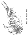
- a modular plug 1 comprises a guide plate 6 for arranging four pairs of wires 2-2', 3-3', 4-4', and 5-5', a housing 7 / for receiving the guide plate 6, and a plurality of terminals 8.
- the wires 2-2', 3-3', 4-4', and 5-5' are twisted for each pair and covered by an insulating sheath to enhance the electric characteristics.
- Eight guide apertures 9 are provided in the guide plate 6 in a zigzag fashion in two rows.
- a plurality of terminal slots 10 extend downwardly from the upper face of the front portion of the housing 7.
- each pair of the wires 2-2', 3-3', 4-4', or 5-5' are stripped of a length of the insulating sheath, untwisted, and inserted into the guide apertures 9 such that the wires are arranged in such an order as shown in Fig. 13; i.e., from left, the third pair 4-4', one of the second pair 3, the first pair 2-2', the other of the second pair 3', and the fourth pair 5-5',
- the guide plate 6 is then fitted into the housing 7, and the terminals 8 are inserted into the terminal slots 10 to pierce into the respective wires 2-5' for electrical connection while the upper ends of the terminals 8 are exposed in the terminal slots 10.
- the wires of each pair are arranged in different rows, especially, the wires 3-3' of the second pair are spaced apart in the different rows, making the wiring work difficult and requiring much labor in assembling the modular plug.
- the distance between the wires 3 and 3' is so 1 arge that the length of untwisted wires becomes large, making it difficult to minimize the crosstalk and/or attenuation.
- a modular plug 21 comprises a guide plate 26 for arranging four pairs of wires 22-22', 23-23', 24-24', and 25-25', and a housing 27 for receiving the guide plate 26.
- the wires 22-25' are high-speed transmission wires having an outside diameter of 1.1 mm and are twisted for each pair and covered by an insulating sheath 30.
- a front portions 31 of the wires 22-25' are stripped of the insulating sheath 30 and untwisted.
- Each front portion 31 is comprised of a single or stranded core wire and an insulating sheath 43 around the core wire.
- the guide plate 26 is made of a synthetic resin to provide an insertion section 33 having a plurality of guide apertures 32 and a pair of extended sections 34 extending forwardly from opposite sides of the insertion section 33. It is preferred that the inside faces of the extended sections 34 are made concave so as to match the outside form of the wire pair.
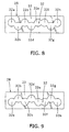
- guide apertures 32a, 32c, 32f, and 32h are arranged in an upper row while guide apertures 32b, 32d, 32e, and 32g are arranged in the lower row.
- the wires 22 and 22' of the firsL pair are inserted in the two guide apertures 32d and 32e at the center while the wires 23 and 23' of second pair are inserted in the guide apertures 32c and 32f that are spaced across the first pair 22-22'.
- the wires 24 and 24' of the third pair are inserted in the guide apertures 32a and 32b adjacent to the wire 23 while the wires 25 and 25' of the fourth pair are inserted in the guide apertures 32g and 32h adjacent to the wire 22'.
- the housing 27 is provided with a front portion 35, forming a cavity section 36 for receiving the guide plate 26 that holds the front portions 31 of respective wires.
- Eight engaging apertures 37 are provided in the front portion 35 such that respective engaging apertures 37a-h correspond to the guide apertures 32a-h of the guide plate 26.
- Eight terminal slots 38 extend downwardly from the upper face of the front portion 35 with a pitch of 1.016 mm and communicate with the respective engaging apertures 37a-h.
- a cantilevered engaging piece 39 extends rearwardly from the bottom of the front portion 35.
- a removable terminal 28 with a bifurcated lower end is inserted in each of the terminal slots 38. It is preferred that all the terminals 28 are made identical in terms of the length and shape.
- a ground sheet 29 covers the housing 27 except: for the terminal slots 38 and the engaging piece 39.
- the ground sheet 29 has a base section 40, a support section 41 extending rearwardly from Lhe bottom of the base section 40, and a U-shaped wire grounding portion 42 Lhat is crimped to a wire shield 44 of the cable 30.
- the front portions 31 of four pairs of wires 22-22', 23-23', 24-24', and 25-25' are untwisted and inserted into the guide apertures 32.
- the wires 22 and 22' of the first pair are arranged in the same lower row
- the wires 23 and 23' of the second pair are arranged in the same upper row. Since the wires 22 and 22' of the first pair are arranged next to each other, Lhe distance between Lhe wires 23 and 23' of the second pair be minimized, resulting in the reduced length of the untwisted front portions.
- the extended sections 34 hold the wire pairs between them so that the front portions of wire pairs are kept in the same condition as arranged by the guide plate 26.
- the quide plate 26 with the four pairs of wires 22-25' is fitted into the cavity section 36 of the housing 27 such that the front portions 31 of the wire pairs are inserted into the engaging apertures 37. Since the arranging condition of the wire pairs is kept. by the guide apertures 32 and the extended sections 34, it is easy to fit the guide plate 26 into the housing 27.
- the terminals 28 are pushed into the terminal slots 38 such that the terminals 28 pierce the insulating sheaths 43 and make contact with the core wires. Consequently, the lower ends of the terminals 28 are electrically connected to the respective wires 22-25' while the upper ends are held in the terminal slots 38.
- the four pairs of wires in the above embodiments may be replaced with two, three, five, or more pairs of wires.
- the guide apertures 32 in two rows in the above embodiments may be arranged in three or more rows.
- the outside diameter of the wires may range from 0.9 to 1.0 mm.
- the wires of the first pair are arranged next to each other and the wires of the second pair are arranged in the same row so that it is easy to assemble the wires and the modular plug.
- the distance between the wires of the second pair and the length of the untwisted portions are made so small that the electrical characteristics, such as crosstalk and/or attenuation are improved.
Landscapes
- Coupling Device And Connection With Printed Circuit (AREA)
- Details Of Connecting Devices For Male And Female Coupling (AREA)
Abstract
Description
The
Claims (8)
- A modular plug comprising:a quide plate having guide apertures capable of arranging at least first and second pairs of wires in at least upper and lower rows;a housing for receiving said guide plate;at least two pairs of terminals provided at positions corresponding to said guide apertures; andsaid guide apertures being arranged such that wires of said first pair are provided next: to each other and wires of said second pair are spaced across said first pair in the same row.
- The modular plug according to claim 1, wherein said wires of said first pair are provided in the same row.
- The modular plug according to claim 1 or 2, wherein wires of a third pair and wires of a fourth pair are provided adjacent to a wire and the other wire of said second pair, respectively.
- The modular plug according to claim 3, wherein an outside wire of said third pair, an outside wire of said fourth pair, and said wires of said second pair are provided one of said two rows while an inside wire of said third pair, an inside wire of said fourth pair, and said wires of said first pair are provided in the other row.
- A harnessed modular plug comprises:at least first and second pairs of wires;a guide plate having at least two pairs of guide apertures capable of arranging said wires of said first and second pairs in at least upper and lower rows;a housing for receiving said guide plate;at least Lwo pairs of terminal provided in said housing at positions corresponding to said guide apertures;said wires of said first pair being arranged next to each other while said wires of said second pair are spaced across said first pair in the same row.
- The harnessed modular plug according to claim 5, wherein said wires of said first pair are arranged in the same row.
- The harnessed modular plug according to claim 6, wherein wires of a third pair and wires of a fourth pair are arranged adjacent to a wire and the other of said second pair, respectively.
- The harnessed modular plug according to claim 7, wherein an outside wire of said third pair, an outside wire of said fourth pair, and said wires of said second pair are arranged in one of said two rows while an inside wire of said third pair, an inside wire of said fourth pair, and said wires of said first pair are arranged in the other row.
Applications Claiming Priority (2)
| Application Number | Priority Date | Filing Date | Title |
|---|---|---|---|
| JP2000081460A JP3708785B2 (en) | 2000-03-23 | 2000-03-23 | Modular plug and harness products |
| JP2000081460 | 2000-03-23 |
Publications (3)
| Publication Number | Publication Date |
|---|---|
| EP1137122A2 true EP1137122A2 (en) | 2001-09-26 |
| EP1137122A3 EP1137122A3 (en) | 2002-01-23 |
| EP1137122B1 EP1137122B1 (en) | 2004-09-01 |
Family
ID=18598393
Family Applications (1)
| Application Number | Title | Priority Date | Filing Date |
|---|---|---|---|
| EP01107202A Expired - Lifetime EP1137122B1 (en) | 2000-03-23 | 2001-03-22 | Modular plug and harnessed plug |
Country Status (4)
| Country | Link |
|---|---|
| US (1) | US6332802B2 (en) |
| EP (1) | EP1137122B1 (en) |
| JP (1) | JP3708785B2 (en) |
| DE (1) | DE60105214T2 (en) |
Cited By (1)
| Publication number | Priority date | Publication date | Assignee | Title |
|---|---|---|---|---|
| WO2012107310A1 (en) * | 2011-02-08 | 2012-08-16 | Robert Bosch Gmbh | Direct plug connector for making direct electrical contact with a printed circuit board |
Families Citing this family (18)
| Publication number | Priority date | Publication date | Assignee | Title |
|---|---|---|---|---|
| US6962503B2 (en) * | 2000-01-10 | 2005-11-08 | Ortronics, Inc. | Unshielded twisted pair (UTP) wire stabilizer for communication plug |
| JP4199961B2 (en) * | 2002-06-26 | 2008-12-24 | ヒロセ電機株式会社 | Modular plug |
| US7017267B2 (en) * | 2003-10-15 | 2006-03-28 | James Allen Carroll | Method and apparatus for zone cabling |
| US20060160407A1 (en) * | 2004-06-24 | 2006-07-20 | Carroll James A | Network connection system |
| WO2007084095A2 (en) * | 2004-06-24 | 2007-07-26 | Carroll James A | Network connection system |
| US7415760B2 (en) * | 2005-11-22 | 2008-08-26 | Sbc Knowledge Ventures, L.P. | Apparatus for pre-forming a twisted-pair electrical cable |
| US7335066B2 (en) | 2005-12-16 | 2008-02-26 | James A. Carroll | Network connector and connection system |
| US7201604B1 (en) * | 2006-03-16 | 2007-04-10 | John Mezzalingua Associates, Inc. | Ethernet cable connector and methods of use thereof |
| JP4883726B2 (en) | 2009-05-11 | 2012-02-22 | ヒロセ電機株式会社 | Modular plug |
| US7905744B1 (en) | 2009-10-20 | 2011-03-15 | John Mezzalingua Associates, Inc. | Cartridge lock registered jack and method of use thereof |
| JP6518143B2 (en) * | 2015-06-18 | 2019-05-22 | タイコエレクトロニクスジャパン合同会社 | Connection member and connector of twisted pair electric wire |
| KR102390264B1 (en) * | 2016-05-04 | 2022-04-22 | 센티넬 커넥터 시스템즈, 아이엔씨. | Industrial Large Conductor Plug |
| US10191899B2 (en) | 2016-06-06 | 2019-01-29 | Comigo Ltd. | System and method for understanding text using a translation of the text |
| TWI642241B (en) * | 2017-09-15 | 2018-11-21 | 林宗光 | Electrical connector device |
| JP2019079609A (en) * | 2017-10-20 | 2019-05-23 | 株式会社オートネットワーク技術研究所 | UTP cable and connector |
| JP6958589B2 (en) * | 2019-04-25 | 2021-11-02 | Smk株式会社 | Electrical connector |
| DE102022004461B4 (en) | 2022-11-23 | 2024-07-18 | Telegärtner Karl Gärtner GmbH | Connector core and connectors |
| DE102023002670B3 (en) | 2023-06-26 | 2024-05-29 | Telegärtner Karl Gärtner GmbH | Cable connectors |
Family Cites Families (8)
| Publication number | Priority date | Publication date | Assignee | Title |
|---|---|---|---|---|
| US5571035A (en) * | 1994-10-31 | 1996-11-05 | The Whitaker Corporation | Divergent load bar |
| US5727962A (en) * | 1995-09-29 | 1998-03-17 | Caveney; Jack E. | Modular plug connector |
| US5899770A (en) * | 1996-11-05 | 1999-05-04 | Hirose Electric Co., Ltd. | Modular plug and modular jack |
| AU9402598A (en) * | 1997-09-26 | 1999-04-23 | Whitaker Corporation, The | Modular plug having load bar for crosstalk reduction |
| US6083052A (en) * | 1998-03-23 | 2000-07-04 | The Siemon Company | Enhanced performance connector |
| US6080007A (en) * | 1998-11-30 | 2000-06-27 | Hubbell Incorporated | Communication connector with wire holding sled |
| US6193542B1 (en) * | 1998-11-30 | 2001-02-27 | Stewart Connector Systems, Inc. | Modular electrical plug and plug-cable assembly including the same |
| US6123572A (en) * | 1999-10-15 | 2000-09-26 | Toshiki Tamura | Modular plug for a signal transmission cable |
-
2000
- 2000-03-23 JP JP2000081460A patent/JP3708785B2/en not_active Expired - Fee Related
-
2001
- 2001-03-21 US US09/813,000 patent/US6332802B2/en not_active Expired - Fee Related
- 2001-03-22 EP EP01107202A patent/EP1137122B1/en not_active Expired - Lifetime
- 2001-03-22 DE DE60105214T patent/DE60105214T2/en not_active Expired - Lifetime
Cited By (3)
| Publication number | Priority date | Publication date | Assignee | Title |
|---|---|---|---|---|
| WO2012107310A1 (en) * | 2011-02-08 | 2012-08-16 | Robert Bosch Gmbh | Direct plug connector for making direct electrical contact with a printed circuit board |
| CN103339802A (en) * | 2011-02-08 | 2013-10-02 | 罗伯特·博世有限公司 | Direct plug connectors for direct electrical contact to printed circuit boards |
| CN103339802B (en) * | 2011-02-08 | 2016-11-09 | 罗伯特·博世有限公司 | For directly making electrical contact with the direct plug-in connector of printed circuit board (PCB) |
Also Published As
| Publication number | Publication date |
|---|---|
| US6332802B2 (en) | 2001-12-25 |
| EP1137122A3 (en) | 2002-01-23 |
| JP3708785B2 (en) | 2005-10-19 |
| US20010024902A1 (en) | 2001-09-27 |
| JP2001267023A (en) | 2001-09-28 |
| EP1137122B1 (en) | 2004-09-01 |
| DE60105214D1 (en) | 2004-10-07 |
| DE60105214T2 (en) | 2005-11-03 |
Similar Documents
| Publication | Publication Date | Title |
|---|---|---|
| EP1137122B1 (en) | Modular plug and harnessed plug | |
| EP1295363B1 (en) | High speed connector | |
| EP0971444B1 (en) | Modular plug having a circuit board | |
| AU601107B2 (en) | Connecting block construction | |
| EP1014498B1 (en) | Communication cable terminating plug | |
| US7753717B2 (en) | High speed data plug and method for assembly | |
| EP0840406A2 (en) | Modular plug and modular jack | |
| EP0398560B1 (en) | Insulation displacement connector | |
| JP3486775B2 (en) | Electrical cable connector and cable assembly | |
| WO1998013899A1 (en) | Patch cord connector | |
| US20080014801A1 (en) | Wire guide and connector assembly using same | |
| US7249962B2 (en) | Connector assembly | |
| US7097513B2 (en) | Telecommunication connector | |
| JP3433254B2 (en) | Electrical connector having a wire operating mechanism | |
| EP0590796B1 (en) | Mixed coaxial connector | |
| US7722410B2 (en) | Plug | |
| US6325660B1 (en) | Low crosstalk communication connector | |
| EP1195854A1 (en) | Modular plug and method of coupling a cable with twisted wire pair to the same | |
| EP1263092B1 (en) | Network data transmission cable connector | |
| KR100335220B1 (en) | Structure for preventing noise of connector pin | |
| JPS5832223Y2 (en) | Plug with cable for subscriber switching connection board | |
| EP1195855A2 (en) | Modular plug and method of coupling a cable to the same | |
| HK26894A (en) | Connecting block construction |
Legal Events
| Date | Code | Title | Description |
|---|---|---|---|
| PUAI | Public reference made under article 153(3) epc to a published international application that has entered the european phase |
Free format text: ORIGINAL CODE: 0009012 |
|
| AK | Designated contracting states |
Kind code of ref document: A2 Designated state(s): DE GB Kind code of ref document: A2 Designated state(s): AT BE CH CY DE DK ES FI FR GB GR IE IT LI LU MC NL PT SE TR |
|
| AX | Request for extension of the european patent |
Free format text: AL;LT;LV;MK;RO;SI |
|
| PUAL | Search report despatched |
Free format text: ORIGINAL CODE: 0009013 |
|
| AK | Designated contracting states |
Kind code of ref document: A3 Designated state(s): AT BE CH CY DE DK ES FI FR GB GR IE IT LI LU MC NL PT SE TR |
|
| AX | Request for extension of the european patent |
Free format text: AL;LT;LV;MK;RO;SI |
|
| RIC1 | Information provided on ipc code assigned before grant |
Free format text: 7H 01R 24/04 A, 7H 01R 23/00 B |
|
| 17P | Request for examination filed |
Effective date: 20020524 |
|
| AKX | Designation fees paid |
Free format text: DE GB |
|
| 17Q | First examination report despatched |
Effective date: 20030616 |
|
| GRAP | Despatch of communication of intention to grant a patent |
Free format text: ORIGINAL CODE: EPIDOSNIGR1 |
|
| GRAS | Grant fee paid |
Free format text: ORIGINAL CODE: EPIDOSNIGR3 |
|
| GRAA | (expected) grant |
Free format text: ORIGINAL CODE: 0009210 |
|
| RIC1 | Information provided on ipc code assigned before grant |
Ipc: 7H 01R 24/04 A |
|
| AK | Designated contracting states |
Kind code of ref document: B1 Designated state(s): DE GB |
|
| REG | Reference to a national code |
Ref country code: GB Ref legal event code: FG4D |
|
| REG | Reference to a national code |
Ref country code: IE Ref legal event code: FG4D |
|
| REF | Corresponds to: |
Ref document number: 60105214 Country of ref document: DE Date of ref document: 20041007 Kind code of ref document: P |
|
| PLBE | No opposition filed within time limit |
Free format text: ORIGINAL CODE: 0009261 |
|
| STAA | Information on the status of an ep patent application or granted ep patent |
Free format text: STATUS: NO OPPOSITION FILED WITHIN TIME LIMIT |
|
| 26N | No opposition filed |
Effective date: 20050602 |
|
| PGFP | Annual fee paid to national office [announced via postgrant information from national office to epo] |
Ref country code: GB Payment date: 20110316 Year of fee payment: 11 |
|
| GBPC | Gb: european patent ceased through non-payment of renewal fee |
Effective date: 20120322 |
|
| PG25 | Lapsed in a contracting state [announced via postgrant information from national office to epo] |
Ref country code: GB Free format text: LAPSE BECAUSE OF NON-PAYMENT OF DUE FEES Effective date: 20120322 |
|
| PGFP | Annual fee paid to national office [announced via postgrant information from national office to epo] |
Ref country code: DE Payment date: 20130320 Year of fee payment: 13 |
|
| REG | Reference to a national code |
Ref country code: DE Ref legal event code: R119 Ref document number: 60105214 Country of ref document: DE |
|
| REG | Reference to a national code |
Ref country code: DE Ref legal event code: R079 Ref document number: 60105214 Country of ref document: DE Free format text: PREVIOUS MAIN CLASS: H01R0024040000 Ipc: H01R0024640000 |
|
| REG | Reference to a national code |
Ref country code: DE Ref legal event code: R119 Ref document number: 60105214 Country of ref document: DE Effective date: 20141001 Ref country code: DE Ref legal event code: R079 Ref document number: 60105214 Country of ref document: DE Free format text: PREVIOUS MAIN CLASS: H01R0024040000 Ipc: H01R0024640000 Effective date: 20141128 |
|
| PG25 | Lapsed in a contracting state [announced via postgrant information from national office to epo] |
Ref country code: DE Free format text: LAPSE BECAUSE OF NON-PAYMENT OF DUE FEES Effective date: 20141001 |