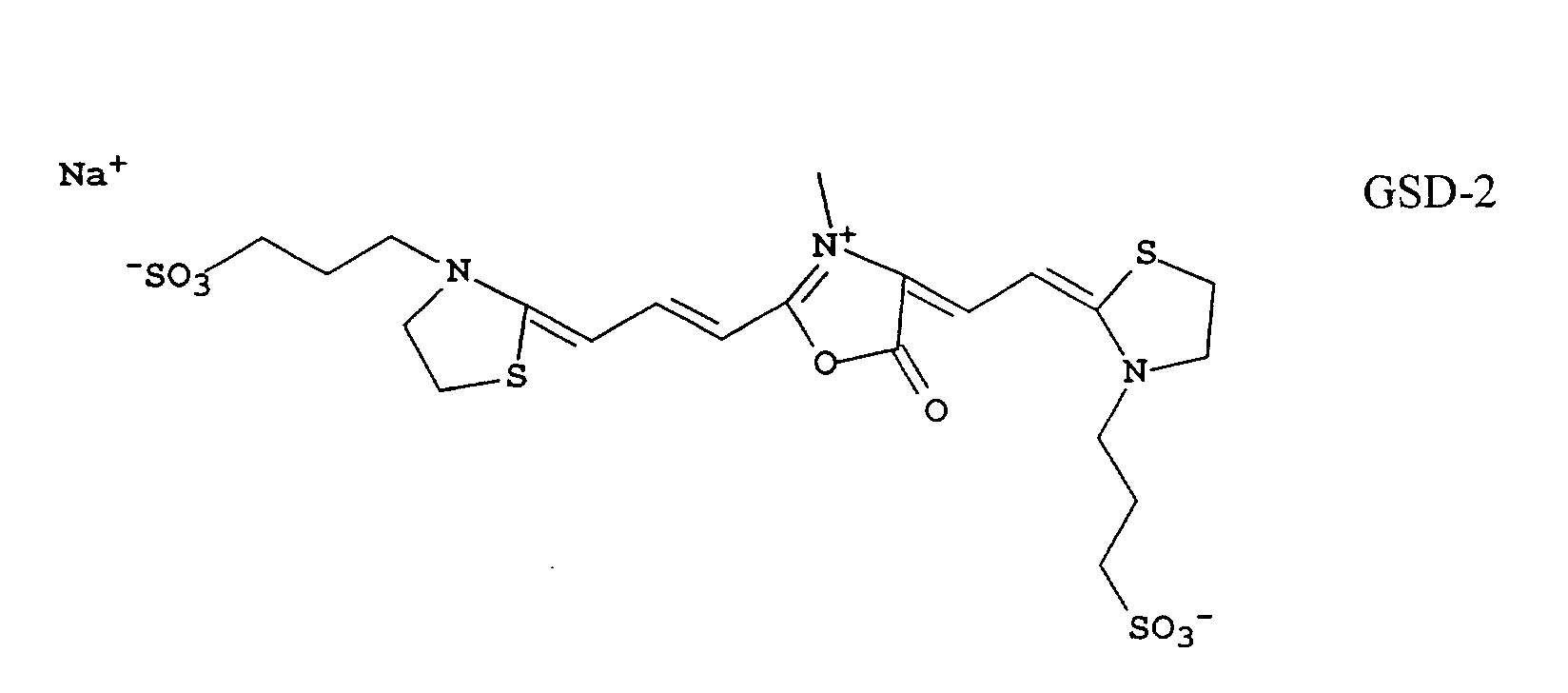
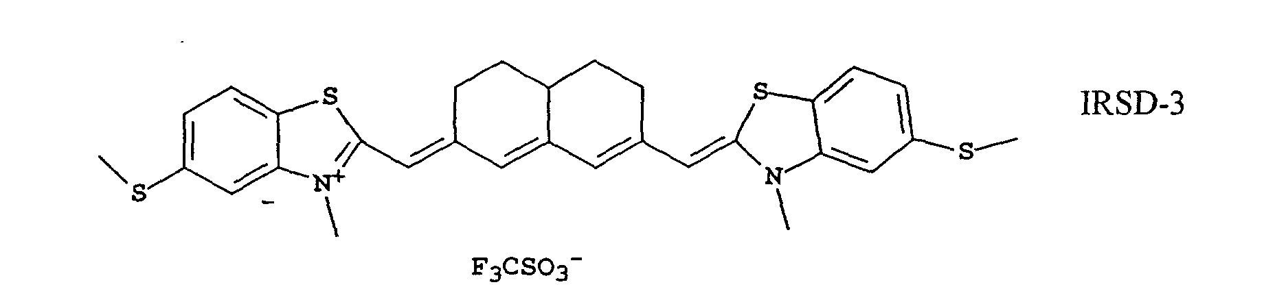
FIELD OF THE INVENTION
This invention relates to silver halide photographic systems and
methods for incorporating and recovering metadata, such as sound data, into a
photographic image and is specifically concerned with the incorporation of non-visually
perceptible sound information into a photograph.
BACKGROUND OF THE INVENTION
With the advent of digital printing capability in silver halide
systems, the ability to combine information such as text, numbers, or other
information, to color photographs has become possible. The use of computers and
sophisticated computer software make it possible to combine digital image data
originating from sources such as a digital camera, a computer image or from a
silver halide film or paper, which had been electronically scanned, with additional
information, then send the combined encoded data to a digital film or paper writer
to produce a photograph.
The conversion of non-image wise information such as text,
numbers or other graphics, commonly known as metadata, to digital information
is well known in many industries. Converting analogue sound information to a
digital data is also well known, and many digital still cameras and all video-recording
cameras have this feature. The desire to include sound information with
pictures has long been a goal. In video cameras, sound is captured with the image
on videotape and replayed through a television. In still cameras, the ability to
record sound exists, but the capability to embed the sound information along with
the pictorial information has been elusive despite several strategies.
Akamine et al in U. S. Patent 5,664,557 has disclosed a system for
recording and reproducing sound as a visible 2-dimensional bar code using a
thermal printer. The recorded sound can be printed onto a label and then affixed
to an object such as a photograph and subsequently scanned with a bar code reader
by the viewer. The reader reinterprets the bar code as sound data and then plays
the sound through a speaker. The difficulty with this system is that the sound
image and the pictorial image are spatially and temporally separate. In addition, if
the label is affixed to the back of the image, the viewer cannot conveniently place
the image in an album where it would first have to be removed in order to be
interpreted. If the label is affixed to the image itself, it detracts from the image
and if affixed to the album, requires its own space in the album and detracts from
the aesthetic quality of the album. Hence, it is clearly more desirable for the
picture to have the sound associated with it, but in an invisible way so that it not
detract from the quality of the picture or album or inconvenience the viewer in any
other way.
The ability to include sound information and image information
has been demonstrated in the motion picture industry with the integral sound track
technology. The sound track is comprised of a spatially separate ribbon of
developed silver placed along side the frame containing the image. The silver
sound image remains in the film by a unique step in the processing cycle so that it
is not removed with the silver used to form the image. The 'sound' file is written
onto the film in a separate exposing step using a sound negative. The 'sound'
information is read from the print film by using an infrared sensor to measure the
modulation of the silver image as a function of density and time. To achieve high
fidelity sound images, a large range of developed silver density is required.
Because of the added complexity to the processing chemistry and
the number of additional steps required to include the sound track, other strategies
have evolved to overcome these problems. One such strategy has been described
by Ciurca et al in US Patent 4,178,183 and improved upon by Fernandez et al in
US Patent 4,233,389. These inventions replace the silver sound track with one
comprised of an infrared light absorbing dye. The coupler which forms the dye is
coated in the film in a 4th sensitized layer, and after exposure and development
forms an infrared dye whose density is proportional to the sound signal from the
sound negative. Modulation of this 4th infrared dye forming layer then produces a
response similar to that of a developed silver sound track, but does not require
special processing of the print film. Much like the silver sound track image, to
reproduce a high fidelity sound, a wide dynamic range of infrared density is
required and as a result, infrared dye densities of at least 3.0 are required in order
to obtain hi-fidelity sound quality.
Hawkins et al in US Patent 5,842,063 teaches that the dye
produced by the coupler in the layer sensitized to record non-imagewise
information should absorb in the regions of the spectrum not appreciably
overlapping with the regions of absorption of the other color records in order that
the developed record of the digital data not interfere with the viewing of the
pictorial records. To accomplish this, he proposes the use of infrared dye forming
couplers coated onto the imaging element in an additional layer to the imaging
records. However, he does not suggest any preferred compositions.
Due to the inherent chemical nature of organic dyes, formed in
chromogenic reactions with para-phenylenediamine type color developers, the
spectral absorption bands are often broader than desired. In color negative films,
the unwanted absorptions of the dyes are compensated for by the colored coupler
masking dyes and by additional chemistry in the film called inter-image chemistry
such as development inhibitor releasing (DIR) chemistry. In the case of couplers
that form infrared dyes, their chemical compositions can be such that a variety of
dyes having different λ-maxs, or peak absorptions, are known.
The unwanted adsorptions of the high density of the infrared dye
required to produce an adequate signal to noise ratio in the motion picture print
film is not an issue when the sound track and the image are spatially distinct.
However, since it is desirable to have the sound image and the pictorial image in
the same spatial area of the print, then the so-called unwanted absorptions of the
infrared image dye must be minimized so that they do not contribute non-imagewise
information to the picture.
It is, therefore, highly desirable to design a system wherein the
photographic element has the ability to record metadata such as sound or other
information in the same spatial area as the imagery with an 'invisible dye' so that
the metadata information does not degrade the pictorial quality of the image and is
co-optimized with the design of the sensor which reads the invisibly encoded
metadata image.
Prior Art:
Ciurca et al in U.S. 4,178,183 discloses a photographic element useful for
forming integral soundtracks, particularly for motion picture print films, by
incorporating micro-crystalline infrared absorbing dyes in a 4th sensitized layer.
Fernandez et al in U.S. 4,233,389 discloses a photographic element useful
for forming integral soundtracks, particularly for motion picture print films, by
incorporating micro-crystalline infrared absorbing dyes in a 4th sensitized layer.
Sakai et al in U.S. 4,208,210 discloses a photographic element useful for
forming integral soundtracks, particularly for motion picture print films, by
incorporating infrared absorbing dyes in a 4th sensitized layer wherein the 4th
sensitized layer is sensitive to the ultraviolet light.
Powers et al in U.S. 4,816,378 discloses an imaging process and
photographic element useful for forming half-tone color proof images by
incorporating a 4th sensitized layer which contains a black or infrared dye.
Hawkins et al in U.S. 5,842,063 discloses a camera, film and method for
recording overlapping visual and digital images in the same region of the film.
Soscia et al in U.S. Application Serial No. 09/099,616 filed June 18, 1998,
discloses a method and apparatus for reading invisibly printed sound data on an
object, the invisible sound data being imprinted by an invisible dye from a thermal
dye transfer process, an invisible printing ink, or a special photographic printing
paper containing an infrared absorbing layer.
Soscia et al in U.S. Application Serial No. 09/099,627 filed June 18, 1998,
discloses a system and apparatus for printing invisible sound data on an object the
sound data component being comprised of an infrared dye, the invisible sound
data being imprinted by an invisible dye from a thermal dye transfer process.
Haraga et al in European Patent Application EP 0 915 374 A1 describes an
imaging method comprising a photographic element containing a 4th sensitized
layer which is designed to add invisible image information to an image.
Patton et al in U. S. Patent 5,774,752 describes a method for processing
photographic still images having sound information associated with them.
Akamine et al in U. S. Patent 5,664,557 describes an audio data
recording/reproduction system for printing optically readable code on
photographic paper as a visible image.
Haga in U. S. Patent 5,629,512 describes an information reading apparatus
for reading invisible information encoded in an underlying layer of a recording
medium which fluoresces upon being exposed to light of a specific wavelength.
Parton et al in U.S. Patent 5,108,882 describes a photographic element
having at least one photographic emulsion layer which is sensitized to infrared
light.
Inoue et al in U. S. Patent 5,313,235 describes a sound playback apparatus
capable of decoding magnetically encoded sound information which has been
previously encoded into an image recording medium such as a photograph..
PROBLEM TO BE SOLVED BY THE INVENTION
There is a need to record metadata in a photographic image.
SUMMARY OF THE INVENTION
One object of the invention is to provide a novel photographic
element capable of recording metadata in a way that the quality of the pictorial
image is not diminished.
Another object of the invention is to provide the novel process of
combining metadata information, such as sound, with pictorial information.
Another object of the invention is to provide a photographic
element, which requires no special processing to produce the metadata or sound
image.
These objects are accomplished by a photographic element which
contains at least a first silver halide layer containing a yellow dye forming
coupler, a second silver halide layer containing a magenta dye forming coupler, a
third silver halide layer containing a cyan dye forming coupler, and a fourth silver
halide layer containing an infrared dye forming coupler, wherein the characteristic
vector of the cyan dye normalized to a density of 1.0 has a density of less than 0.4
at 700 nm, more preferably less than 0.35 and most preferably less than 0.2.
BRIEF DESCRIPTION OF THE DRAWINGS
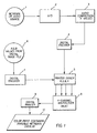
Fig. 1 is a schematic diagram showing how a source of metadata,
such as an audio signal, is converted to a digital signal, encoded, passed to a 4-color
film/paper writer in combination with the R,G,B values from a pictorial
image file, multiplexed, then printed as an invisible image onto a color
photograph.
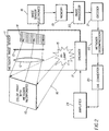
Fig. 2 is a schematic diagram of a hand held reader and its elements
within that sense the invisible metadata image in the picture, reads the signal,
decodes the information, and then reproduces it as sound through a speaker.
ADVANTAGEOUS EFFECT OF THE INVENTION
The invention provides a system for incorporating metadata in a
photographic element.
DETAILED DESCRIPTION OF THE INVENTION
The invention provides a photographic system, including a 4-channel
digital film writer, a false sensitized photographic element capable of
being digitally exposed and which provides a 4th sensitized layer to record
invisible metadata information, such as sound, a hand-held metadata reader which
senses the invisible metadata image in the element, decodes the metadata
information, and reproduces the digital signal as sound or other information.
The term 'metadata', as used herein, refers to any information
separate and apart from the actual image of the picture seen by the end user. As
such, metadata may be text, numbers, or other coded information, including audio,
binary, digital or graphic information which, when encoded and included with the
image, adds information to the image without adding to or subtracting from image
content. Metadata, in general, may be visible or invisible. In this application, the
metadata information is spatially coincident with the image information, it is
preferred to be invisible, either by its lack of color or by its image size (i.e., too
small to see). Examples of metadata are the UPC codes currently used to encode
the price and other information about wholesale or food goods, product code
numbers used to track inventory, e-stamps used for digital postage, etc. In other
photographic applications, metadata may include the date of film printing and
processing, information regarding the type of film negative, the color correction
codes used in printing, the name of the photofinisher, etc.
The system and process for perceptibly integrating sound
information onto film, a label, or other hard object is described in detail in U.S.
Patents 5,644,557; 5,313,235; 5,774,752 and for incorporating non-perceptible
information onto film or reflective print pictures in U.S. Patents 4,208,210;
5,629,512; 5,919,730 and U.S. Application Serial Nos. 09/099,627 and
09/099,616.
The design of this system requires the definition of the response
characteristics of the various elements of the system. Each element plays a crucial
role in the design. This is not to say that various substitutions could not be made
for elements such as the response of a sensor or filter or illuminant. It is to say
only that to define the requirements of a system, each element be well
characterized so that its characteristic response is known.
The elements of the system which need to be specified are:
Design requirements to achieve the performance of the integrated
system:
1. Digital Film/Paper Writer for Metadata Encoding
The schematic diagram in Fig. 1 depicts the collection, encoding,
and writing of the metadata and image information onto a four-color false
sensitized color photograph. The metadata, or sound file (1), such as that captured
and stored by many digital film cameras today, is first digitized (2) (if necessary).
Since a 10-second sound bite may convert to a digital file of perhaps 400 k-bytes
or larger, it is desirable to compress the file to a smaller size. Many software
algorithms are available that accomplish audio compression (3), such as that from
Digital Voice Systems, Inc., AMBE-1000 Voice Coder.
After compression, the data file may be further encoded (4) for
printing in a digital file format known as "Paper Disk". This encoding software is
available from Cobblestone Software, Inc., in Lexington, Mass.
On a parallel path, as shown in Fig. 1, is the image information
from the original pictorial scene, which may have been captured on film or in a
digital camera. If the original image was made on film, the image must first be
scanned in a film or paper scanner to record the R,G,B values as a function of
pixel position in the image. This process creates a spatial array of R,G,B values
proportional to the amounts of red, green, and blue light in the original scene and
stores them as a function of pixel position (6). A common digital picture storage
file format is called JPEG (jpg).
This digital image file is then read and re-encoded (7) in a format
compatible with the digital printer. This information is subsequently transmitted
to the printer driver engine (5) where it is combined with the encoded metadata
sound file then the 4-channel R,G,B,X file, where the X-channel represents the
metadata channel, is read and the code values are sent to the 4-channel multiplexer
(8) of the digital printer.
The multiplexer (8) drives the 4-color digital printer (9). This
printer contains the four light sources that have been matched to the spectral
sensitivities of the output writing media (10), a color paper, for example. The
printer is driven to scan pixel by pixel across the media, and the four different
light sources are modulated in proportion the different amounts of light necessary
to expose the R,G,B pictorial image and the X-metadata image. In principle, this
process could be accomplished in two separate steps. The first in writing the
pictorial information and the second writing the metadata information, but in
practice, it is more efficient to have the signals combined and write all four
simultaneously.
There are numerous commercially available digital printers in the
market place. Their design generally is based upon the type of illuminant source
chosen to expose the media. Illuminant sources have generally fallen into four
categories: Lasers, laser diodes, light emitting diodes (LED's), or cathode ray
tubes (CRT's). LED's as the choice of light source are commercially available
over a wide range of wavelengths, are compact, and their power output is stable
and easy to regulate. A representative sampling of LED's is given below:
| Manufacturer | Type/Model | Output Wavelength |
| Siemens Corp. | GaN, LB5416 | 430 nm |
| Nichia Chemical Industries Ltd. | GaN, NSPB-WR | 470 nm |
| Nichia Chemical Industries Ltd. | GaN, NSPG-Rank-H | 526 nm |
| Hewlett-Packard | HLMP-GJ10 | 621 nm |
| Hewlett-Packard | HLMP-GL10 | 635 nm |
| Marktech Co. | MT5000F-UR | 695 nm |
The digital printer light sources are preferably unique sources and
different in their spectral output by approximately 50 nm. It is also useful to have
the printer sources be narrowly collimated so that the output wavelengths are
singularly unique and as closely matched to the spectral sensitivities of the four-color
paper as possible. The printer electronics drive the location of the exposing
bean of mixed, modulated light across the media. This is frequently accomplished
by exposing the beam onto a rapidly rotating polygon whose facets are aligned
with the media. Preferred light sources are lasers, laser diodes, and LED's due to
their narrow output bandwidth and their ability to be modulated at high frequency.
Combinations of different types of light sources are also acceptable.
2. Design of the Photographic Element
The system comprises the photographic element containing an
additional imaging layer, other than the R, G, B layers already present in all color
systems. This layer can be exposed with light of some pre-determined wavelength
in a digital printer whose wavelength corresponds to the spectral sensitivity of the
emulsion that is coated within said 4th sensitized layer. The spectral sensitivity of
this layer is unique compared to the spectral sensitivities of the imaging layers so
that when the exposure is made onto the element which will record the metadata,
the layers containing the imaging chemistry to produce the pictorial image are not
in any way exposed or compromised. This is typically accomplished by choosing
an exposing light source which is approximately 50 nm different in wavelength
from the other exposing light sources and modulating the power level of this light
source so as not to expose the pictorial imaging records. Thus in addition to the
red, green and blue exposures given the element to produce the pictorial
information, an additional 4th exposure is made which contains the metadata
information.
In this invention, since the pictorial portion of the photographic
element has spectral sensitivities in the blue region at about 473nm, in the green
region at about 550 nm and in the red region at about 695 nm, the 4
th sensitized
layer could be designed to be exposed at one any of several locations. One
opportunity is to place the spectral sensitization in the near infrared region, or
somewhat past 700 nm, more preferably past 750 nm so as not to confuse the
response of this layer with the red sensitive layer. Digital exposing devices are
readily available at a variety of wavelengths that have sufficient power output and
a narrow wavelength of power distribution to meet this requirement. Many such
devices are already used in the health imaging field to expose digital x-ray, MRI,
CAT, or other films used by this industry.
| Writing Channel | Spectral Sensitivity |
| Red | 695 nm |
| Green | 550 nm |
| Blue | 473 nm |
| X | 430 nm |
| Or X | 625 nm |
| Or X | 765 nm |
| Or X | 820 nm |
A typical multicolor photographic element comprises a support
bearing a cyan dye image forming layer comprised of at least one red light
sensitive silver halide emulsion having associated therewith at least one cyan dye-forming
coupler, a magenta dye image forming layer comprising at least one
green light sensitive silver halide emulsion having associated therewith at least
one magenta dye-forming coupler, and a yellow dye image forming layer
comprising at least one blue-sensitive silver halide emulsion having associated
therewith at least one yellow dye-forming coupler. The element can contain
additional layers, such as filter layers, interlayers, overcoat layers, subbing layers,
and the like.
In the following discussion of suitable materials for use in the
emulsions and elements that can be used in conjunction with this invention,
reference will be made to Research Disclosure, September 1994, Item 36544,
published by Kenneth Mason Publications, Ltd., Dudley House, 12 North Street,
Emsworth, Hampshire PO10 7DQ, England, which will be identified hereafter by
the term "Research Disclosure."
The silver halide emulsions employed in these photographic
elements can be either negative-working or positive-working. Suitable emulsions
and their preparation as well as methods of chemical and spectral sensitization are
described in Sections I, and III-IV. Vehicles and vehicle related addenda are
described in Section II. Dye image formers and modifiers are described in Section
X. Various additives such as UV dyes, brighteners, luminescent dyes,
antifoggants, stabilizers, light absorbing and scattering materials, coating aids,
plasticizers, lubricants, antistats and matting agents are described, for example, in
Sections VI-IX. Layers and layer arrangements, color negative and color positive
features, scan facilitating features, supports, exposure and processing can be found
in Sections XI-XX.
Further, it would be advantageous to practice elements of the
invention in conjunction with the materials disclosed in an article entitled
"Typical and Preferred Color Paper, Color Negative, and Color Reversal
Photographic Elements and Processing" which was published in Research
Disclosure, February 1995, Volume 370. In particular, Sections I-XIII, XV-XVIII,
and XXIIIA are especially relevant.
Any photographic coupler known to the art can be used in
conjunction with elements of the invention. Suitable couplers are described in
Research Disclosure, Item 36544, Section X. In addition, the structures of
particularly preferred couplers can be found in an article entitled "Typical and
Preferred Color Paper, Color Negative, and Color Reversal Photographic
Elements and Processing" which was published in Research Disclosure, February
1995, Volume 370, Section II.
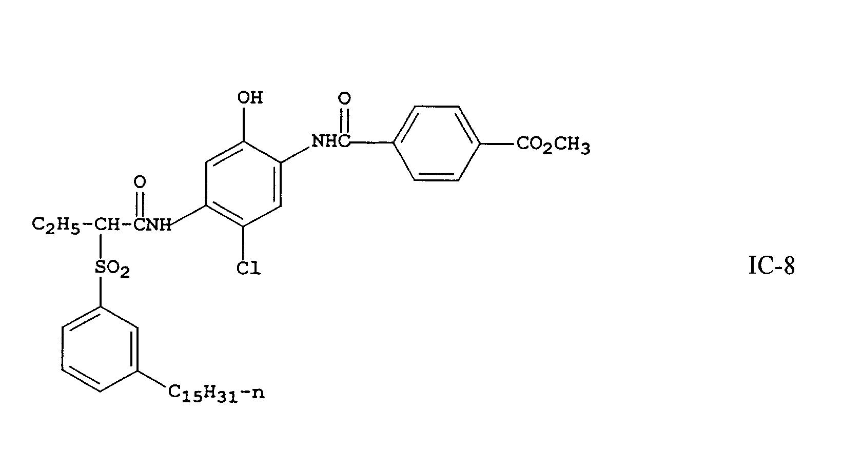
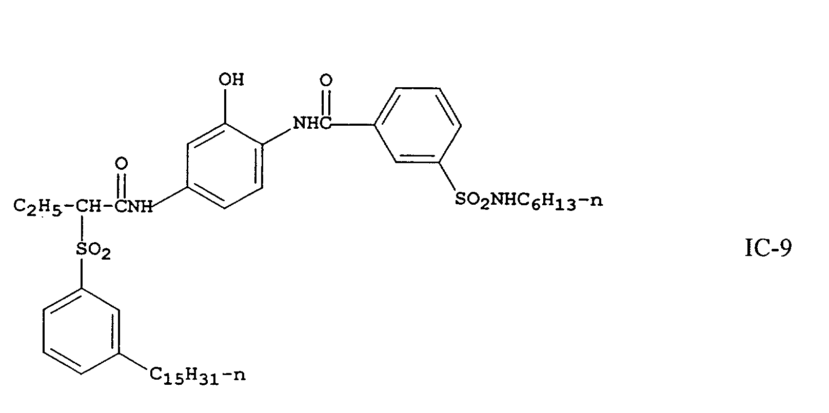
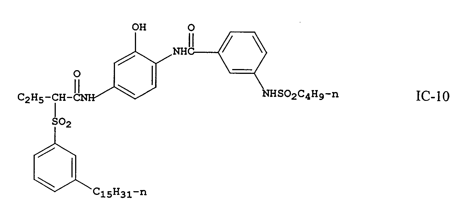
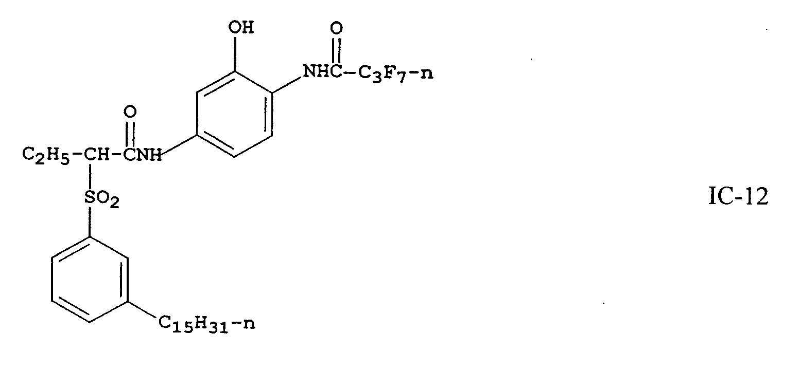
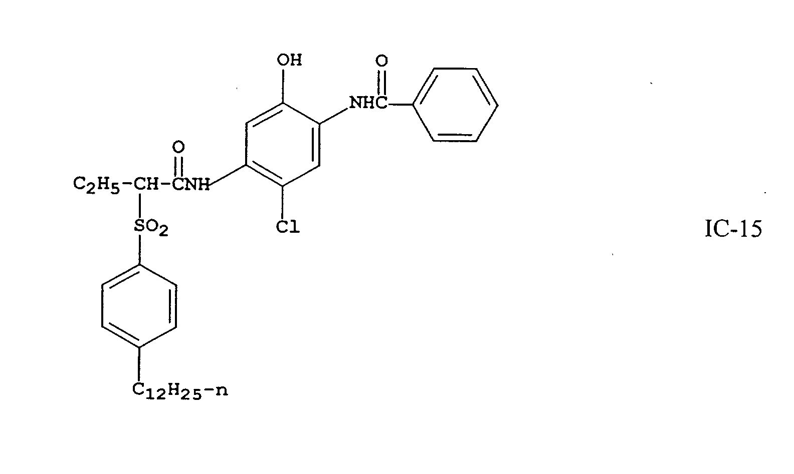
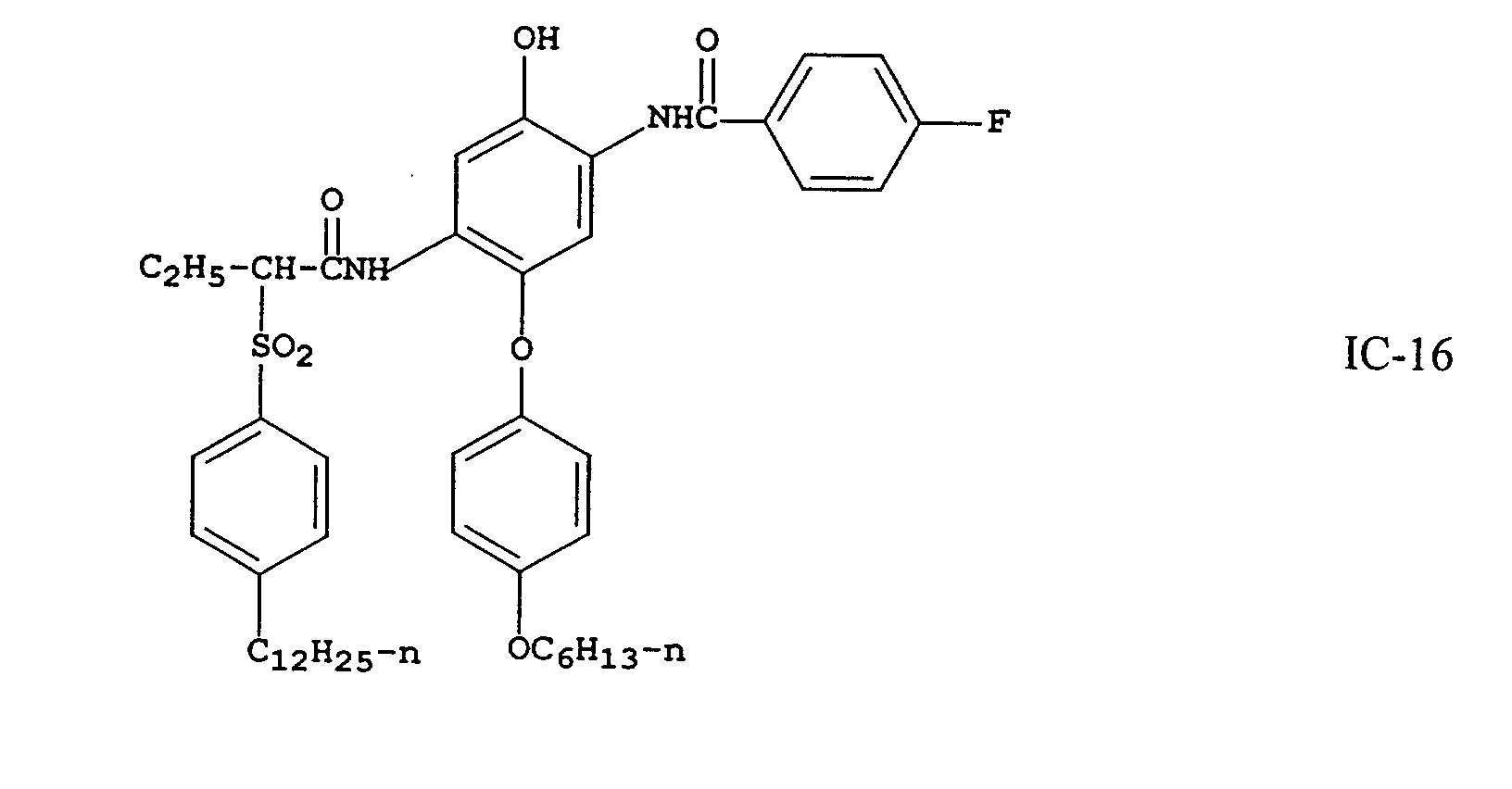
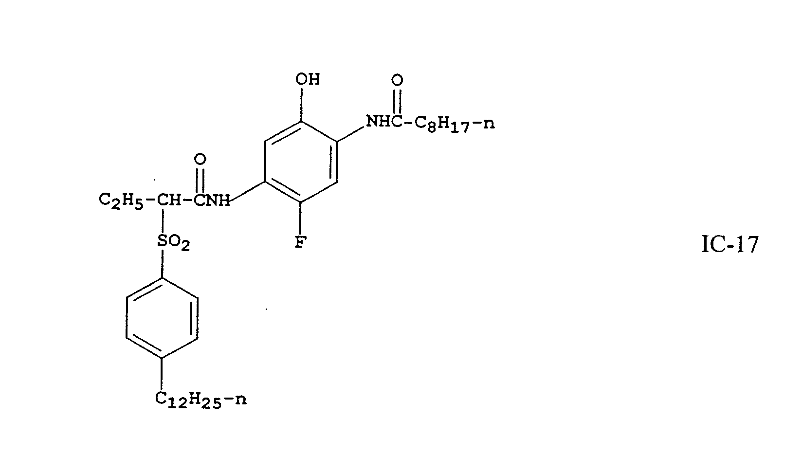
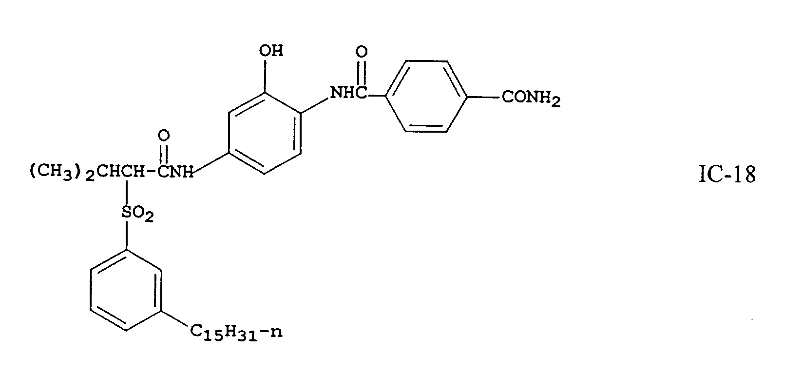
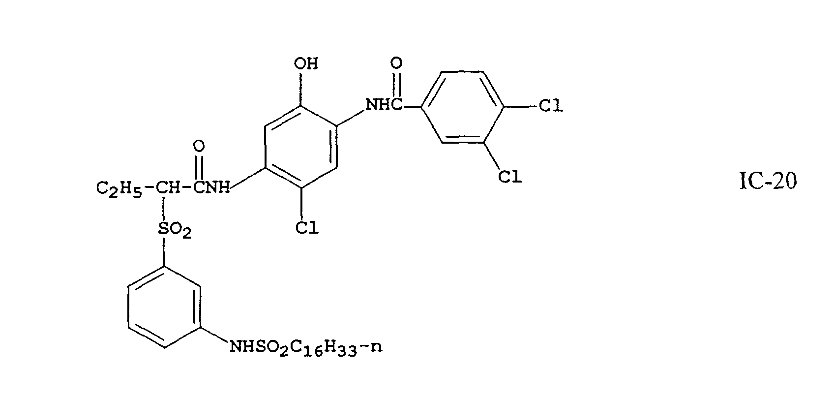
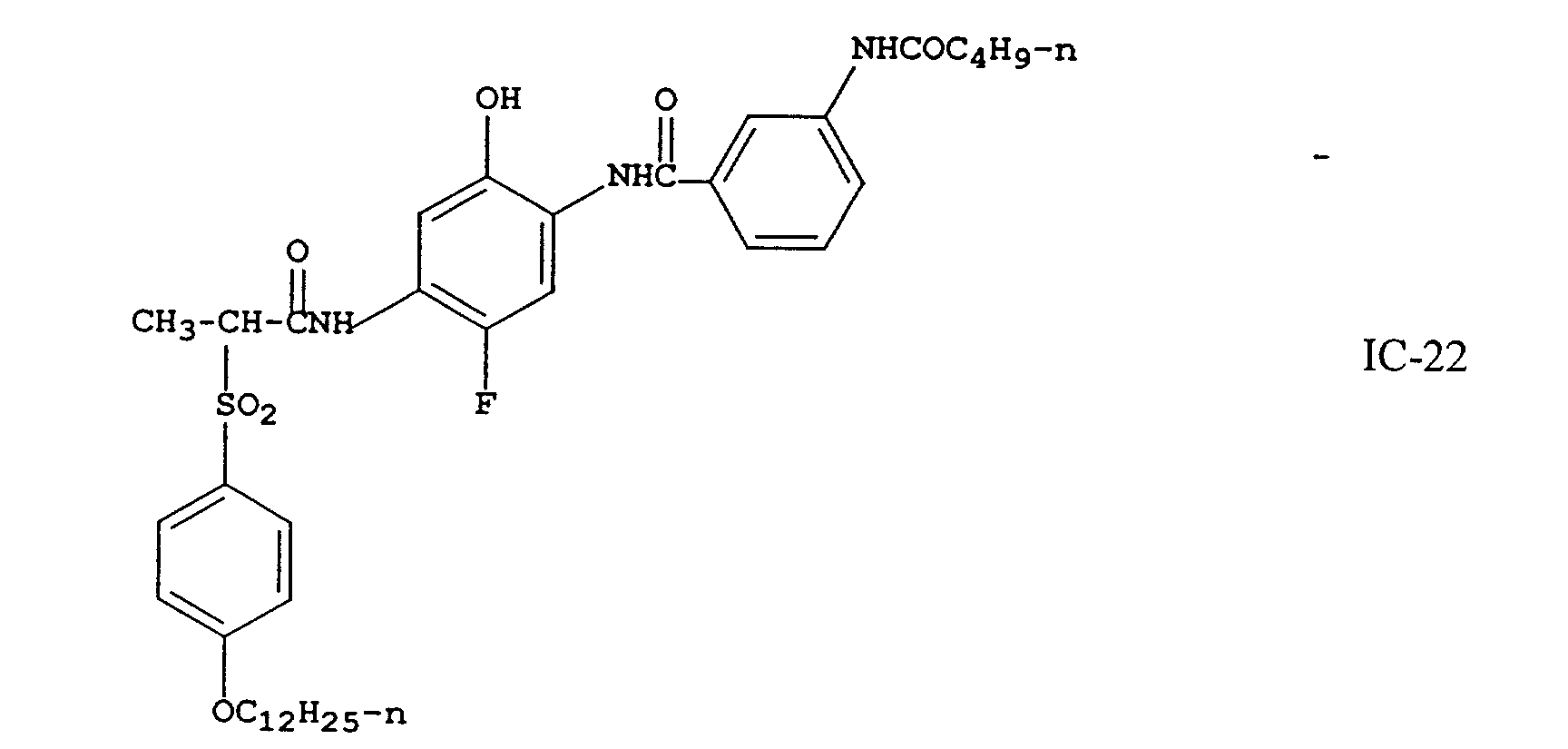
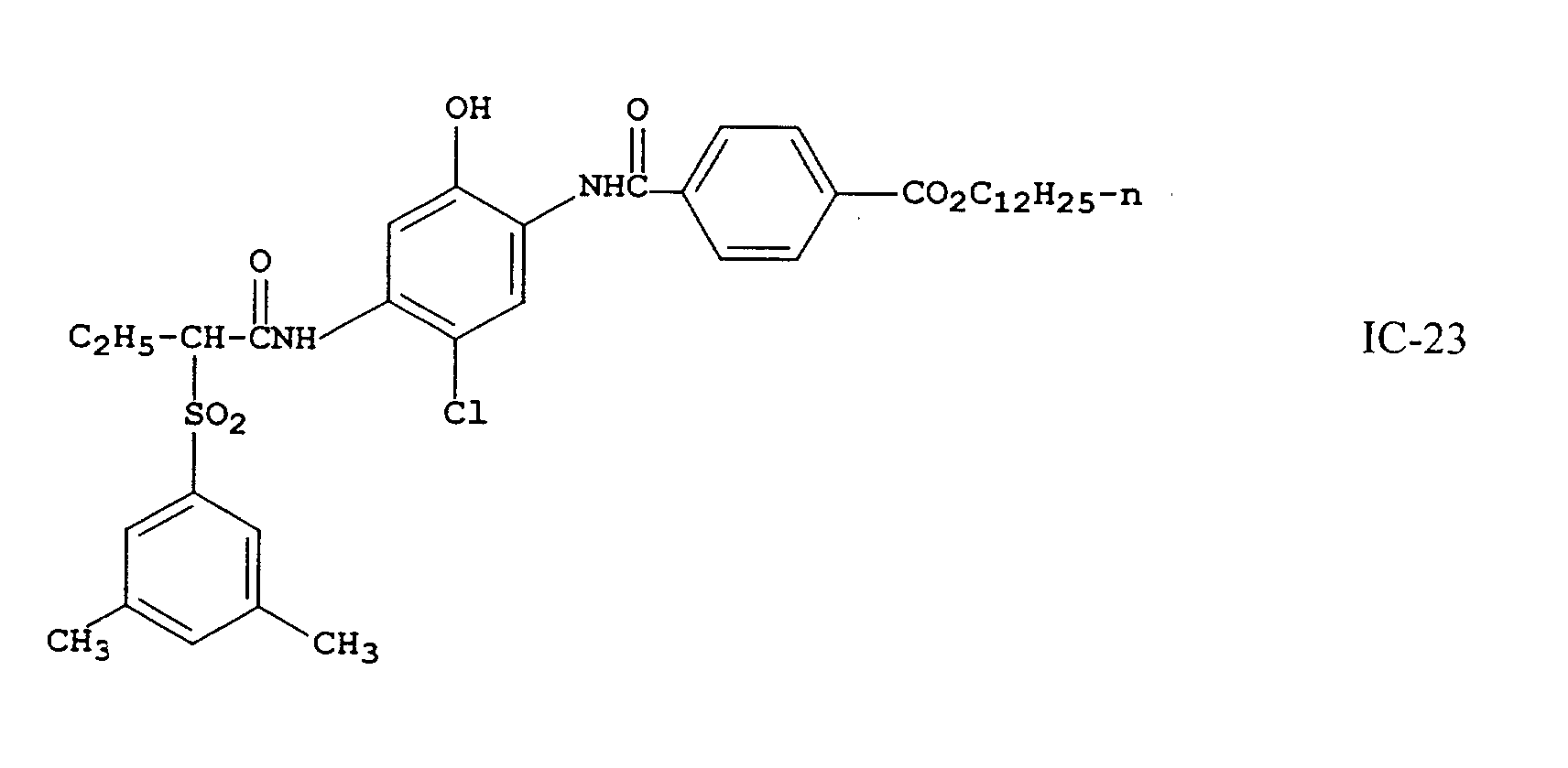
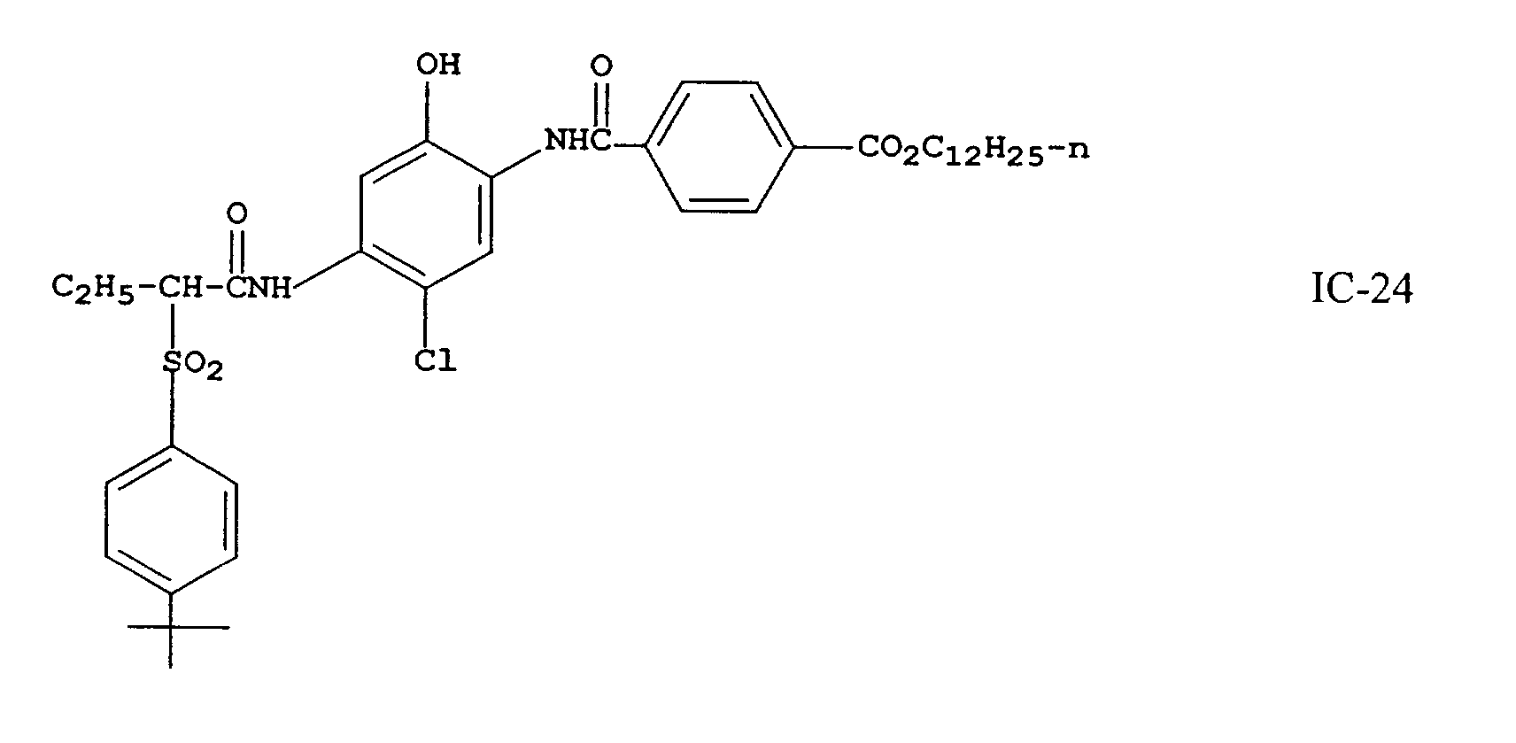
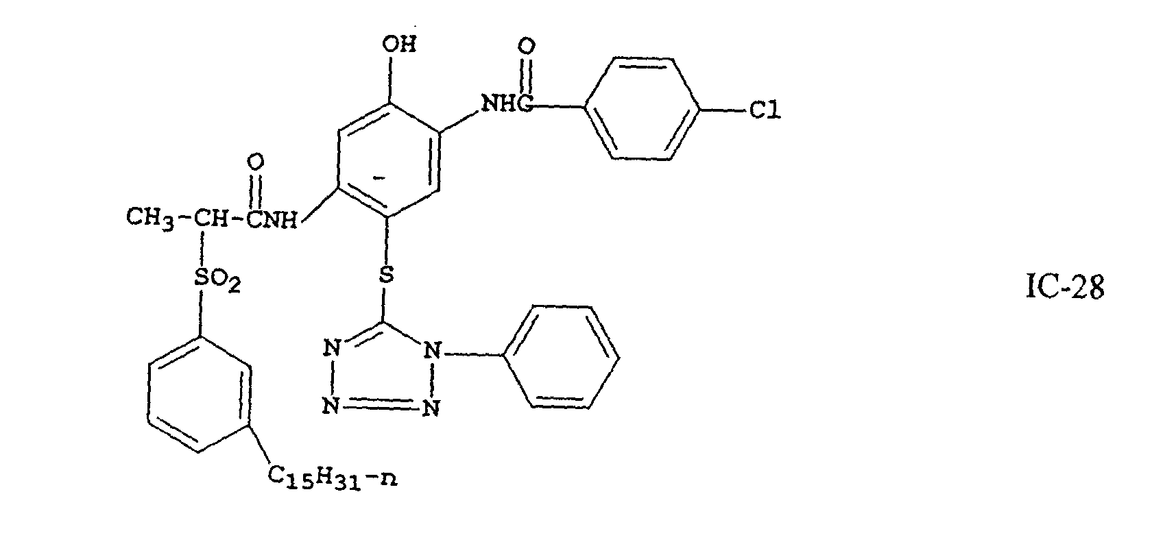
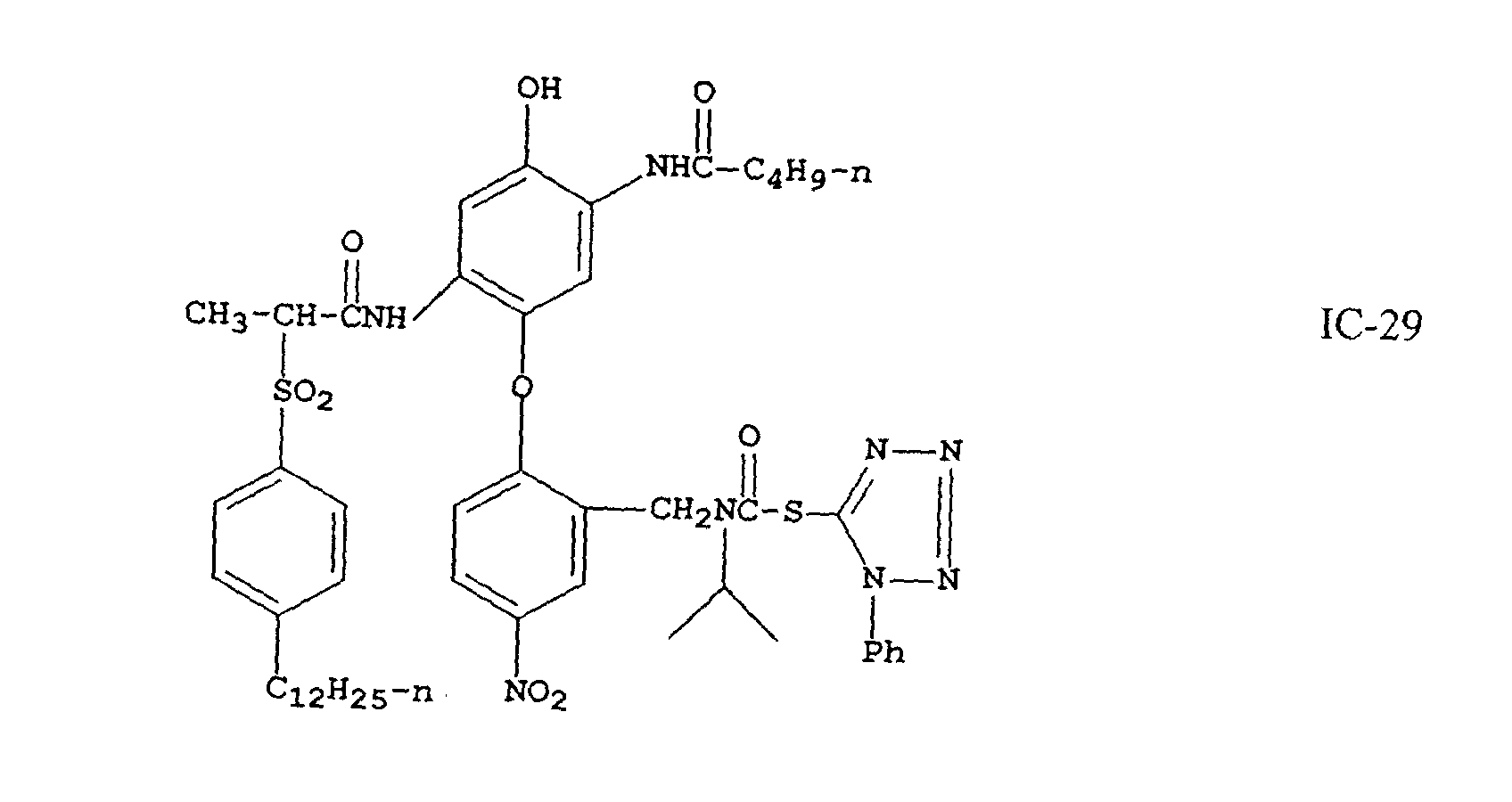
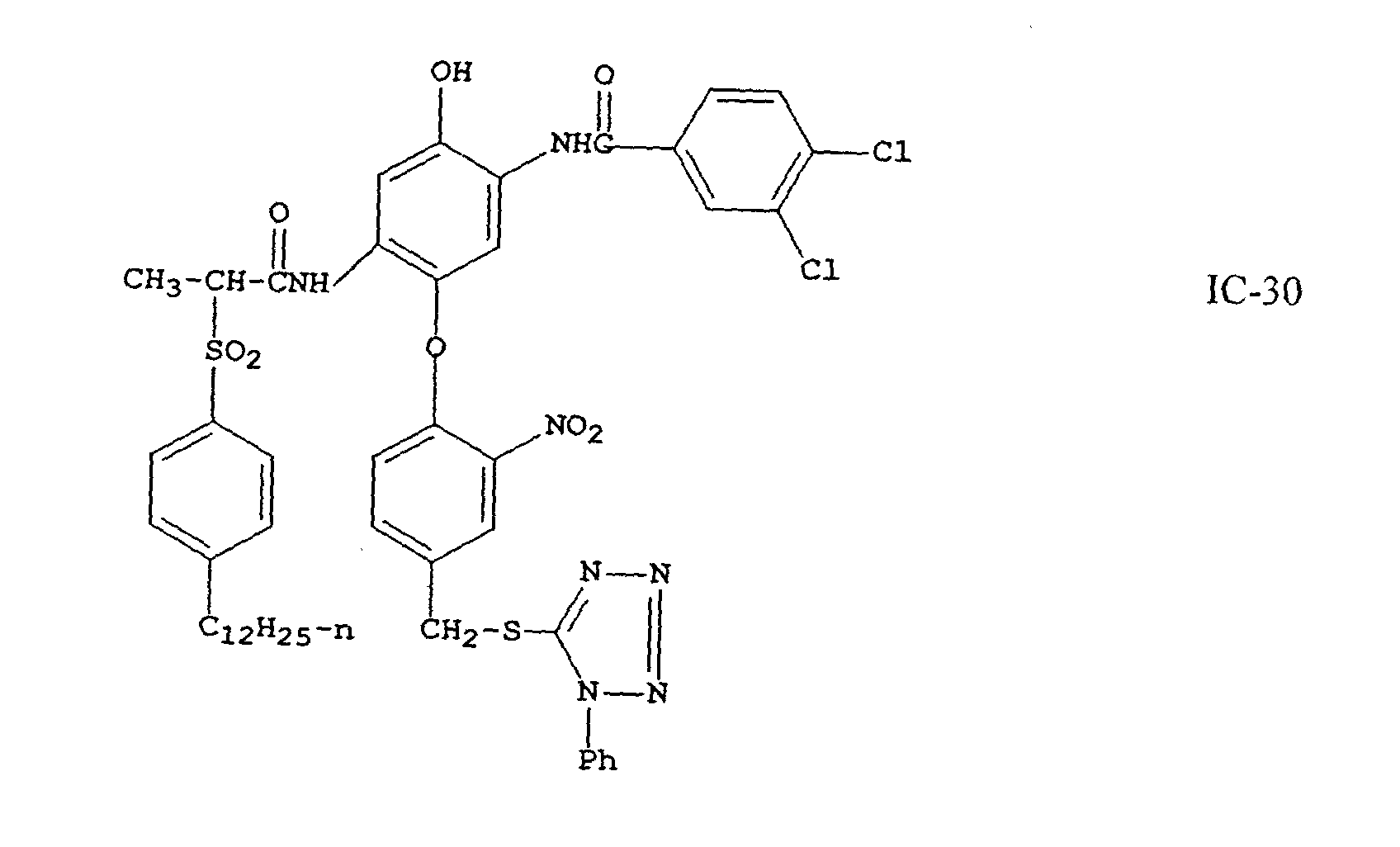
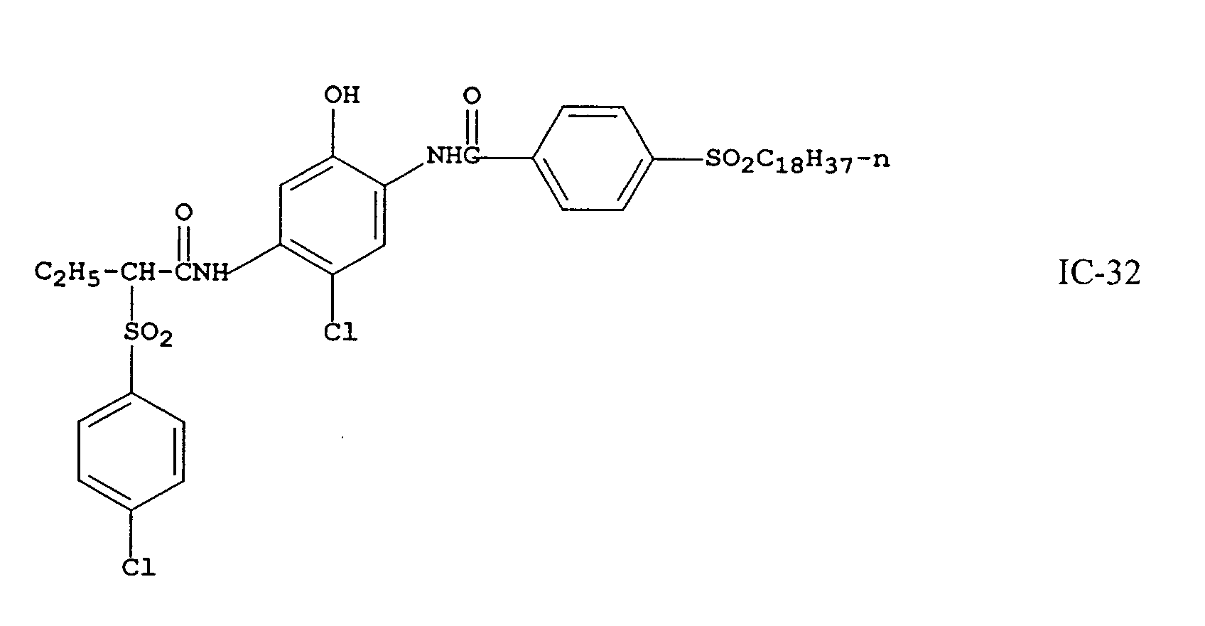
An example of a cyan dye forming coupler of the invention is one
having Formula (I):
wherein
Coupler (I) is a 2,5-diacylaminophenol cyan coupler in which the
5-acylamino moiety is an amide of a carboxylic acid which is substituted in the
alpha position by a particular sulfone (-SO2-) group. The sulfone moiety must be
an arylsulfone and cannot be an alkylsulfone, and must be substituted only at the
meta or para position of the aryl ring. In addition, the 2-acylamino moiety must
be an amide (-NHCO-) of a carboxylic acid, and cannot be a ureido (-NHCONH-)
group. The result of this unique combination of sulfone-containing amide group
at the 5-position and amide group at the 2-position is a class of cyan dye-forming
couplers which form H-aggregated image dyes having very sharp-cutting dye hues
on the short wavelength side of the absorption curves and absorption maxima
(λmax) generally in the range of 620-645 nanometers, which is ideally suited for
producing excellent color reproduction and high color saturation in color
photographic papers.
Referring to formula (I), R1 represents hydrogen or an alkyl group
including linear or branched cyclic or acyclic alkyl group of 1 to 10 carbon atoms,
suitably a methyl, ethyl, n-propyl, isopropyl or butyl group, and most suitably an
ethyl group.
R2 represents an aryl group or an alkyl group such as a perfluoroalkyl
group. Such alkyl groups typically have 1 to 20 carbon atoms, usually 1 to 4
carbon atoms, and include groups such as methyl, propyl and dodecyl,; a
perfluoroalkyl group having 1 to 20 carbon atoms, typically 3 to 8 carbon atoms,
such as trifluoromethyl or perfluorotetradecyl, heptafluoropropyl or
heptadecylfluorooctyl; a substituted or unsubstituted aryl group typically having 6
to 30 carbon atoms, which may be substituted by, for example, 1 to 4 halogen
atoms, a cyano group, a carbonyl group, a carbonamido group, a sulfonamido
group, a carboxy group, a sulfo group, an alkyl group, an aryl group, an alkoxy
group, an aryloxy group, an alkylthio group, an arylthio group, an alkylsulfonyl
group or an arylsulfonyl group. Suitably, R2 represents a heptafluoropropyl
group, a 4-chlorophenyl group, a 3,4-dichlorophenyl group, a 4-cyanophenyl
group, a 3-chloro-4-cyanophenyl group, a pentafluorophenyl group, a
4-carbonamidophenyl group, a 4-sulfonamidophenyl group, or an
alkylsulfonylphenyl group.
In formula (I), each X is located at the meta or para position of the phenyl
ring, and each independently represents a linear or branched, saturated or
unsaturated alkyl or alkenyl group such as methyl, t-butyl, dodecyl, pentadecyl or
octadecyl; an alkoxy group such as methoxy, t-butoxy or tetradecyloxy; an
aryloxy group such as phenoxy, 4-t-butylphenoxy or 4-dodecylphenoxy; an alkyl
or aryl acyloxy group such as acetoxy or dodecanoyloxy; an alkyl or aryl
acylamino group such as acetamido, benzamido, or hexadecanamido; an alkyl or
aryl sulfonyloxy group such as methylsulfonyloxy, dodecylsulfonyloxy, or 4-methylphenylsulfonyloxy;
an alkyl or aryl sulfamoylamino group such as N-butylsulfamoylamino,
or N-4-t-butylphenylsulfamoylamino; an alkyl or aryl
sulfonamido group such as methanesulfonamido, 4-chlorophenylsulfonamido or
hexadecanesulfonamido; a ureido group such as methylureido or phenylureido; an
alkoxycarbonyl or aryloxycarbonylamino group such as methoxycarbonylamino
or phenoxycarbonylamo; a carbamoyl group such as N-butylcarbamoyl or N-methyl-N-dodecylcarbamoyl;
or a perfluoroalkyl group such as trifluoromethyl or
heptafluoropropyl. Suitably X represents the above groups having 1 to 30 carbon
atoms, more preferably 8 to 20 linear carbon atoms. Most typically, X represents
a linear alkyl group of 12 to 18 carbon atoms such as dodecyl, pentadecyl or
octadecyl.
"n" represents 1, 2, or 3; if n is 2 or 3, then the substituents X may be the
same or different.
Z represents a hydrogen atom or a group which can be split off by the
reaction of the coupler with an oxidized color developing agent, known in the
photographic art as a "coupling-off group". The presence or absence of such
groups determines the chemical equivalency of the coupler, i.e., whether it is a 2-equivalent
or 4-equivalent coupler, and its particular identity can modify the
reactivity of the coupler. Such groups can advantageously affect the layer in
which the coupler is coated, or other layers in the photographic recording material,
by performing, after release from the coupler, functions such as dye formation,
dye hue adjustment, development acceleration or inhibition, bleach acceleration or
inhibition, electron transfer facilitation, color correction, and the like.
Representative classes of such coupling-off groups include, for example,
halogen, alkoxy, aryloxy, heterocyclyloxy, sulfonyloxy, acyloxy, acyl,
heterocyclyl, sulfonamido, heterocyclylthio, benzothiazolyl, phosophonyloxy,
alkylthio, arylthio, and arylazo. These coupling-off groups are described in the
art, for example, in U.S. Patent Nos. 2,455,169; 3,227,551; 3,432,521; 3,467,563;
3,617,291; 3,880,661; 4,052,212; and 4,134,766; and in U.K. Patent Nos. and
published applications 1,466,728; 1,531,927; 1,533,039; 2,066,755A; and
2,017,704A. Halogen, alkoxy and aryloxy groups are most suitable.
Examples of specific coupling-off groups are -Cl, -F, -Br, -SCN, -OCH3,-OC
6H
5,
-OCH
2C(=O)NHCH
2CH
2OH, -OCH
2C(O)NHCH
2CH
2OCH
3,
-OCH
2C(O)NHCH
2CH
2OC(=O)OCH
3, -P(=O)(OC
2H
5)
2, -SCH
2CH
2C00H,
Typically, the coupling-off group is a chlorine atom.
It is essential that the substituent groups R1, R2, X, and Z be selected so as
to adequately ballast the coupler and the resulting dye in the organic solvent in
which the coupler is dispersed. The ballasting may be accomplished by providing
hydrophobic substituent groups in one or more of the substituent groups R1, R2,
X, and Z. Generally a ballast group is an organic radical of such size and
configuration as to confer on the coupler molecule sufficient bulk and aqueous
insolubility as to render the coupler substantially nondiffusible from the layer in
which it is coated in a photographic element. Thus the combination of substituent
groups R1, R2, X, and Z in formula (I) are suitably chosen to meet these criteria.
To be effective, the ballast must contain at least 8 carbon atoms and typically
contains 10 to 30 carbon atoms. Suitable ballasting may also be accomplished by
providing a plurality of groups which in combination meet these criteria. In the
preferred embodiments of the invention R1 in formula (I) is a small alkyl group.
Therefore, in these embodiments the ballast would be primarily located as part of
groups R2, X, and Z. Furthermore, even if the coupling-off group Z contains a
ballast, it is often necessary to ballast the other substituents as well, since Z is
eliminated from the molecule upon coupling; thus, the ballast is most
advantageously provided as part of groups R2 and X.
The following examples further illustrate the invention. It is not to be
construed that the present invention is limited to these examples.
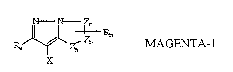
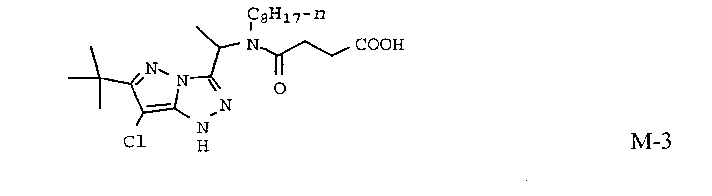
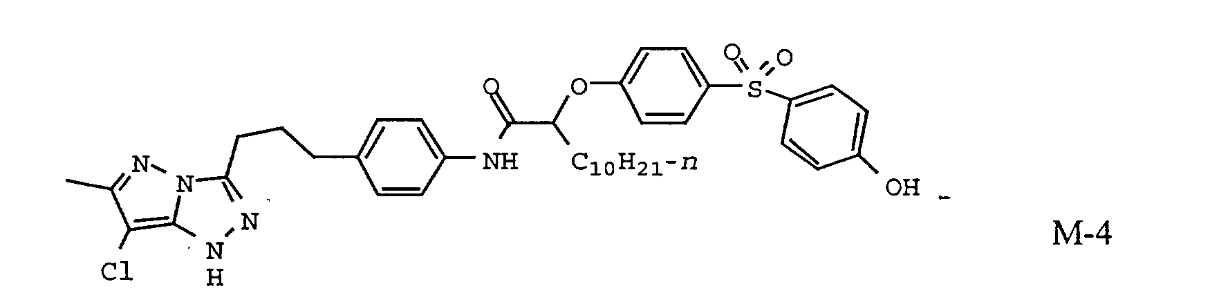
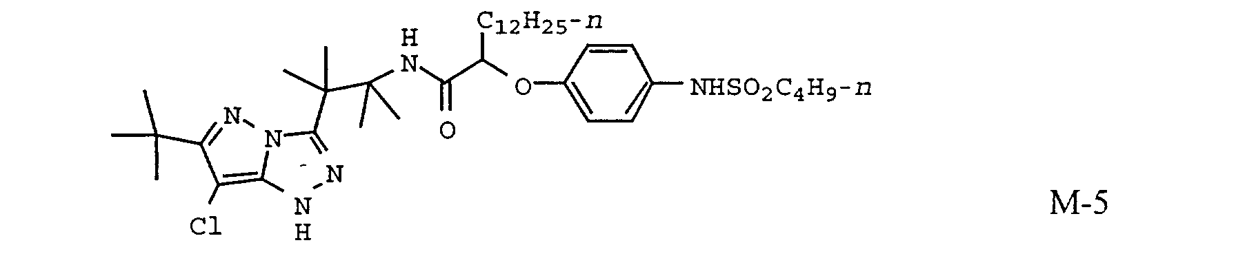
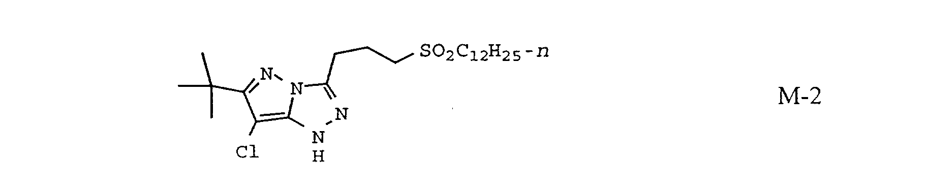
The magenta coupler utilized in the invention may be any magenta
coupler of the following structure:
wherein R
a and R
b independently represent H or a substituent; X is hydrogen or a
coupling-off group; and Z
a, Z
b, and Z
c are independently a substituted methine
group, =N―, =C―, or ―NH―, provided that one of either the Z
a―Z
b bond or
the Z
b―Z
c bond is a double bond and the other is a single bond, and when the
Z
b―Z
c bond is a carbon-carbon double bond, it may form part of an aromatic ring,
and at least one of Z
a, Z
b, and Z
c represents a methine group connected to the
group R
b.
Preferred magenta couplers are 1H-pyrazolo [5,1-c]-1,2,4-triazole
and 1H-pyrazolo [1,5-b]-1,2,4-triazole. Examples of 1H-pyrazolo [5,1-c]-1,2,4-triazole
couplers are described in U.K. Patent Nos. 1,247,493; 1,252,418;
1,398,979; U.S. Patent Nos. 4,443,536; 4,514,490; 4,540,654; 4,590,153;
4,665,015; 4,822,730; 4,945,034; 5,017,465; and 5,023,170. Examples of 1H-pyrazolo
[1,5-b]-1,2,4-triazoles can be found in European Patent applications
176,804; 177,765; U.S Patent Nos. 4,659,652; 5,066,575; and 5,250,400.
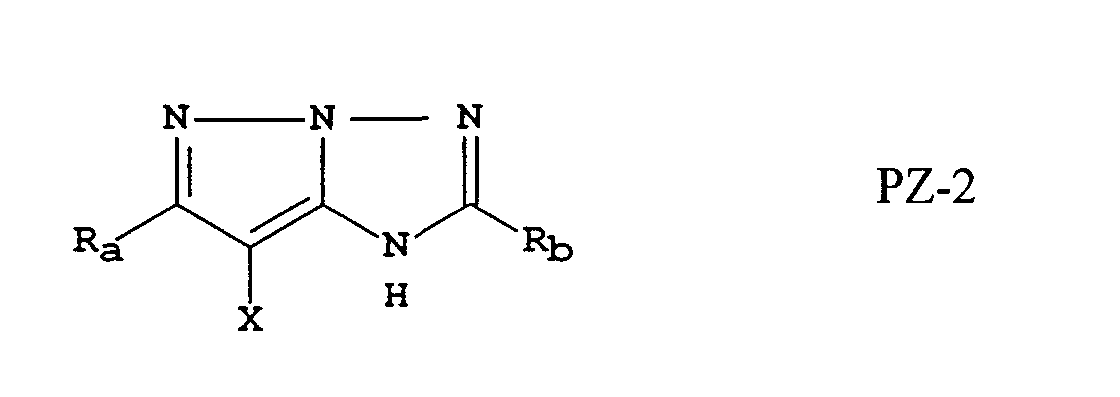
In particular, pyrazoloazole magenta couplers of general structures
PZ-1 and PZ-2 are especially preferred:
wherein R
a, R
b, and X are as defined for MAGENTA-1.
Particularly preferred are the two-equivalent versions of magenta
couplers PZ-1 and PZ-2 wherein X is not equal to a hydrogen. This is the case
because of the advantageous drop in silver required to reach the desired density in
the print element.
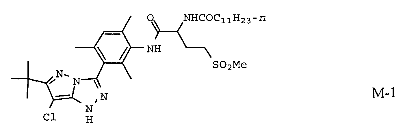
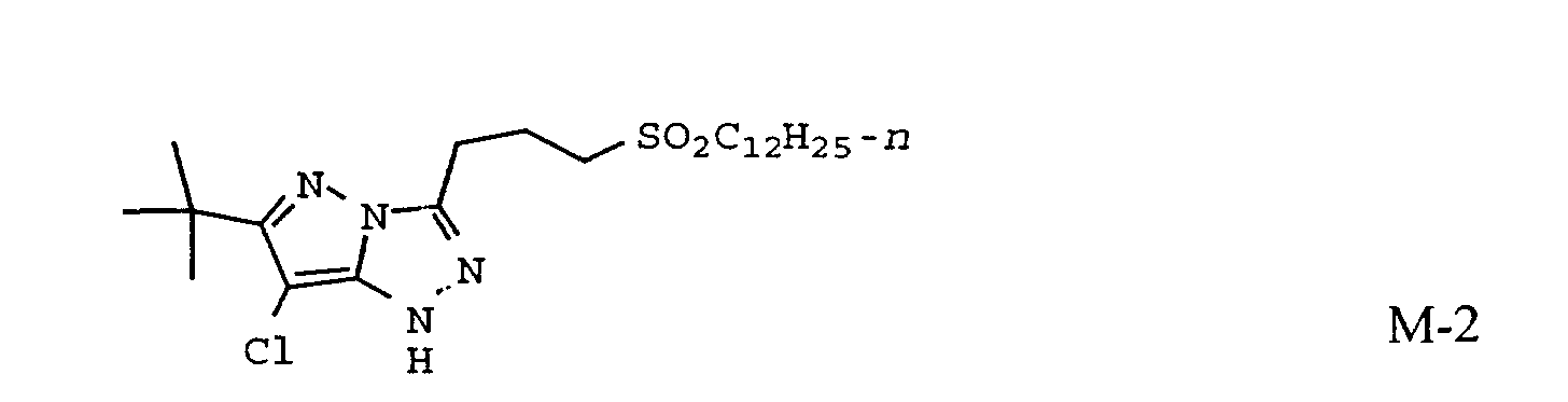
Typical magenta couplers that may be used in the inventive
photographic element are shown below.
The most preferred magenta coupler is
Couplers that form yellow dyes upon reaction with oxidized color
developing agent and which are useful in elements of the invention are described
in such representative patents and publications as: U.S. Patent Nos. 2,875,057;
2,407,210; 3,265,506; 2,298,443; 3,048,194; 3,447,928 and "Farbkuppler - Eine
Literature Ubersicht," published in Agfa Mitteilungen, Band III, pp. 112-126
(1961). Such couplers are typically open chain ketomethylene compounds. Also
preferred are yellow couplers such as described in, for example, European Patent
Application Nos. 482,552; 510,535; 524,540; 543,367; and U.S. Patent No.
5,238,803.
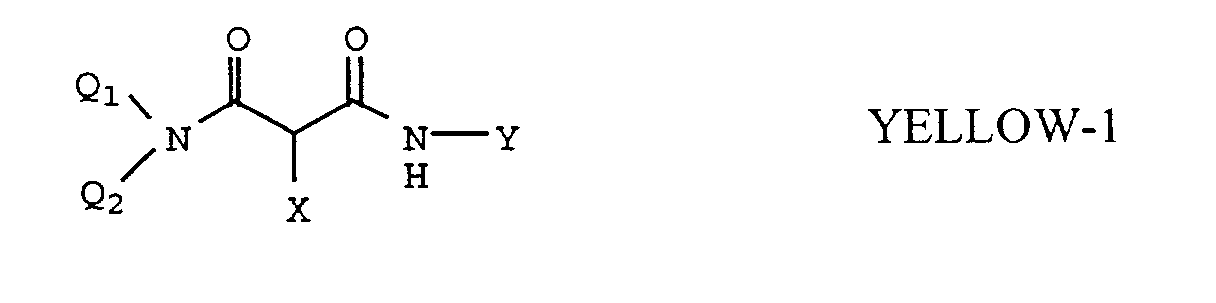
Typical preferred yellow couplers are represented by the following
formulas:
wherein R
1, R
2, R
3, R
4, Q
1 and Q
2 each represents a substituent; X is hydrogen
or a coupling-off group; Y represents an aryl group or a heterocyclic group; Q3
represents an organic residue required to form a nitrogen-containing heterocyclic
group together with the >N―; and Q
4 represents nonmetallic atoms necessary to
from a 3- to 5-membered hydrocarbon ring or a 3- to 5-membered heterocyclic
ring which contains at least one hetero atom selected from N, O, S, and P in the
ring. Particularly preferred is when Q
1 and Q
2 each represents an alkyl group, an
aryl group, or a heterocyclic group, and R
2 represents an aryl or tertiary alkyl
group. Preferred yellow couplers for use in elements of the invention are
represented by YELLOW-4, wherein R
2 represents a tertiary alkyl group, Y
represents an aryl group, and X represents an aryloxy or N-heterocyclic coupling-off
group.
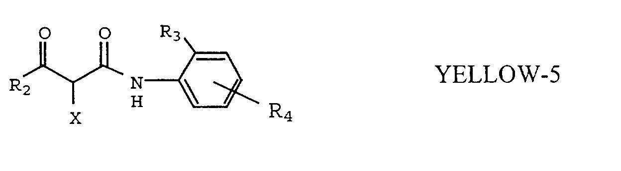
The most preferred yellow couplers are represented by YELLOW-5,
wherein R2 represents a tertiary alkyl group, R3 represents a halogen or an
alkoxy substituent, R4 represents a substituent and X represents a N-heterocyclic
coupling-off group because of their good development and desirable color.
Even more preferred are yellow couplers are represented by
YELLOW-5, wherein R
2, R
3 and R
4 are as defined above, and X is represented
by the following formula:
wherein Z is oxygen of nitrogen and R
5 and R
6 are substituents. Most preferred
are yellow couplers wherein Z is oxygen and R
5 and R
6 are alkyl groups.
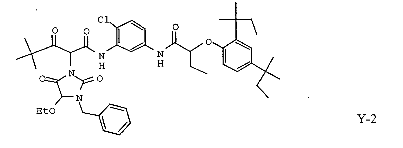
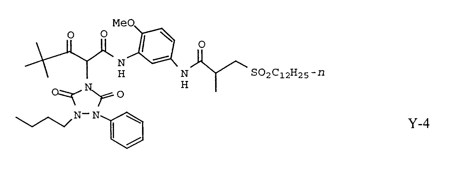
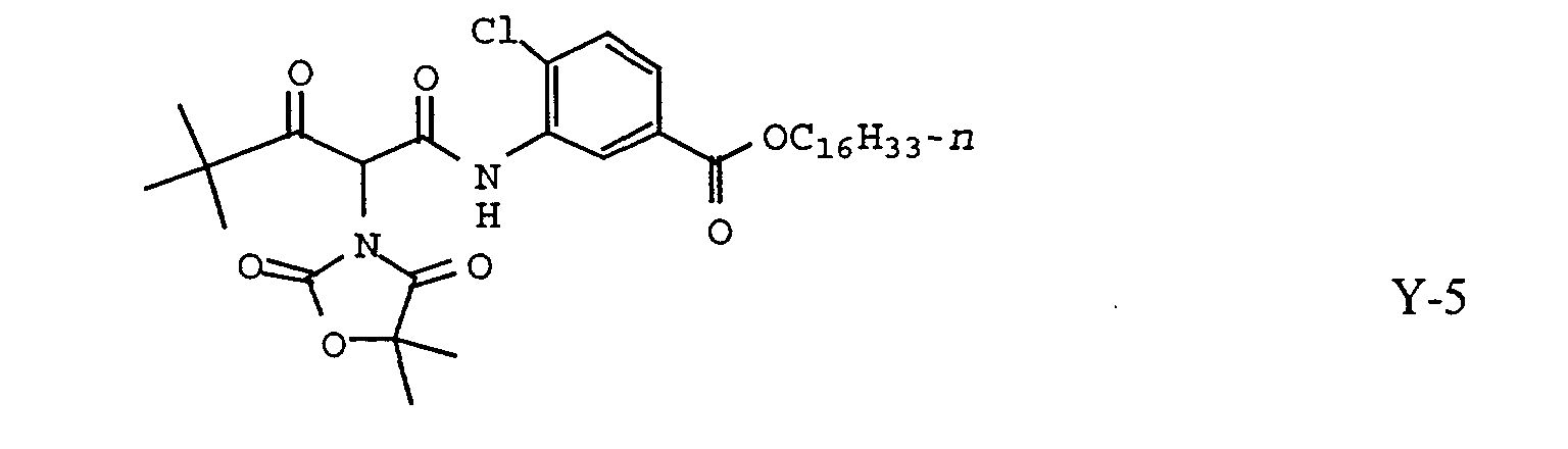
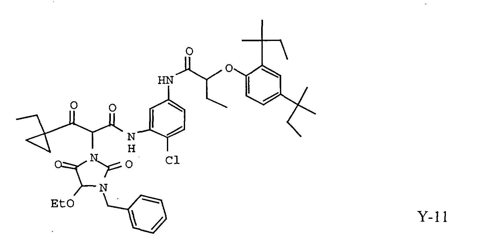
Typical yellow couplers that may be used in the inventive
photographic element are shown below.
To control the migration of various components, it may be
desirable to include a high molecular weight hydrophobe or "ballast" group in the
component molecule. Representative ballast groups include substituted or
unsubstituted alkyl or aryl groups containing 8 to 40 carbon atoms.
Representative substituents on such groups include alkyl, aryl,
alkoxy, aryloxy, alkylthio, hydroxy, halogen, alkoxycarbonyl, aryloxcarbonyl,
carboxy, acyl, acyloxy, amino, anilino, carbonamido (also known as acylamino),
carbamoyl, alkylsulfonyl, arylsulfonyl, sulfonamido, and sulfamoyl groups
wherein the substituents typically contain 1 to 40 carbon atoms. Such substituents
can also be further substituted. Alternatively, the molecule can be made immobile
by attachment to polymeric backbone.
Polymer containing dispersions of yellow photographic couplers
have been employed in color print materials, as described in U.S. Patent
4,857,449. Other methods for preparing polymer-containing dispersions of dye-forming
couplers are described in U.S. Patent Nos. 4,939,077; 4,203,716; and
4,840,885. Commonly, these dispersions are prepared from a solution of a
coupler, an optional high-boiling solvent, an oil-soluble but water-insoluble
polymer, and a volatile organic solvent, which solution is then emulsified and
dispersed in an aqueous solution, often comprising water, a hydrophilic colloid
such as gelatin, and a surfactant. Other methods describe the formation of loaded
latex polymer dispersions using water-miscible or volatile organic solvent. We
have also recently discovered that useful photographic coupler dispersions can be
prepared by forming an loaded polymer latex dispersion, prepared either by high-shear
mixing of a liquid oil phase with a latex-containing aqueous solution, or in
some cases by combining a dispersion of a photographic coupler that is free of
volatile organic solvent with a latex polymer, with sufficient surfactant and
sufficient time to cause formation of a loaded latex dispersion. One of the main
advantages of polymer-containing dispersions described in the prior art have
included image preservability to heat and light, although other advantages in
manufacturing processes, physical performance of the photographic element, and
sensitometric performance have been reported.
Polymer containing dispersions used in the elements of the
invention may be prepared by emulsifying a mixed oil solution comprising
polymer and the photographically useful compounds desired in the dispersion, as
described in U.S. Patents 3,619,195 and 4,857,449.
Polymer-containing dispersions used in the elements of the
invention may also be prepared as loaded latex dispersions. These may be
prepared according to at least three types of process. The first process, described
in, for example, U.S. Patent 4,203,716, involves dissolving the hydrophobic
photographically useful compounds to be loaded in a volatile or water miscible
auxiliary solvent, combining this solution with an aqueous solution containing a
polymer latex, and diluting the dispersion with additional aqueous solution or
evaporating the auxiliary solvent to cause loading to occur. A second, more
preferred method for preparing loaded latex formulations is to subject an oil
solution or an aqueous dispersion of an oil solution comprising photographically
useful compounds, to conditions of high shear or turbulence, in the presence of a
polymer latex, with sufficient shear to cause loading as described in U.S. Patent
5,594,047. A third possible way to prepare some loaded latex formulations is to
simply combine a polymer latex with a dispersed oil solution, such that the oil
solution and latex are miscible, in the presence of surfactant, for a sufficient time
before the dispersion is coated for loading to occur as described in U.S. Patent
5,558,980.
Polymers used in the invention are preferably water-insoluble, and
sufficiently hydrophobic to be incorporated as components of the hydrophobic
dispersed phase of the dispersions used in the elements of the invention. The
polymers may be prepared by bulk polymerization or solution polymerization
processes. Especially preferred among possible polymerization processes is the
free-radical polymerization of vinyl monomers in solution.
Preferred latex polymers of the invention include addition
polymers prepared by emulsion polymerization. Especially preferred are
polymers prepared as latex with essentially no water-miscible or volatile solvent
added to the monomer. Also suitable are dispersed addition or condensation
polymers, prepared by emulsification of a polymer solution, or self-dispersing
polymers.
Especially preferred latex polymers include those prepared by free-radical
polymerization of vinyl monomers in aqueous emulsion. Polymers
comprising monomers which form water-insoluble homopolymers are preferred,
as are copolymers of such monomers, which may also comprise monomers which
give water-soluble homopolymers, if the overall polymer composition is
sufficiently water-insoluble to form a latex.
Examples of suitable monomers include allyl compounds such as
allyl esters (e.g., allyl acetate, allyl caproate, etc.); vinyl ethers (e.g., methyl vinyl
ether, butyl vinyl ether, methoxyethyl vinyl ether, ethoxyethyl vinyl ether,
chloroethyl vinyl ether, 1-methyl-2,2-dimethylpropyl vinyl ether, hydroxyethyl
vinyl ether, diethylene glycol vinyl ether, dimethylaminoethyl vinyl ether,
butylaminoethyl vinyl ether, benzyl vinyl ether, tetrahydrofurfuryl vinyl ether,
etc.); vinyl esters (such as vinyl acetate, vinyl propionate, vinyl butyrate, vinyl
isobutyrate, vinyl dimethyl propionate, vinyl ethyl butyrate, vinyl chloroacetate,
vinyl dichloroacetate, vinyl methoxyacetate, vinyl phenyl acetate, vinyl
acetoacetate, etc.); vinyl heterocyclic compounds (such as N-vinyl oxazolidone,
N-vinylimidazole, N-vinylpyrrolidone, N-vinylcarbazole, vinyl thiophene, N-vinylethyl
acetamide, etc.); styrenes (e.g., styrene, divinylbenzene, methylstyrene,
dimethylstyrene, ethylstyrene, isopropylstyrene, sodium styrenesulfonate,
potassium styrenesulfinate, butylstyrene, hexylstyrene, cyclohexylstyrene,
benzylstyrene, chloromethylstyrene, trifluoromethylstyrene,
acetoxymethylstyrene, acetoxystyrene, vinylphenol,
(t-butoxycarbonyloxy)styrene, methoxystyrene, 4-methoxy-3-methylstyrene,
dimethoxystyrene, chlorostyrene, dichlorostyrene, trichlorostyrene, bromostyrene,
iodostyrene, fluorostyrene, methyl vinylbenzoate ester, vinylbenzoic acid, etc.);
crotonic acids (such as crotonic acid, crotonic acid amide, crotonate esters (e.g.,
butyl crotonate, etc.)); vinyl ketones (e.g., methyl vinyl ketone, etc ); olefins (e.g.,
dicyclopentadiene, ethylene, propylene, 1-butene, 5,5-dimethyl-1-octene, etc.);
itaconic acids and esters (e.g., itaconic acid, methyl itaconate, etc.), other acids
such as sorbic acid, cinnamic acid, methyl sorbate, citraconic acid, chloroacrylic
acid mesaconic acid, maleic acid, fumaric acid, and ethacrylic acid; halogenated
olefins (e.g., vinyl chloride, vinylidene chloride, etc.); unsaturated nitriles (e.g.,
acrylonitrile, etc.); acrylic or methacrylic acids and esters (such as acrylic acid,
methyl acrylate, methacrylic acid, methyl methacrylate, ethyl acrylate, butyl
acrylate, butyl methacrylate, 2-hydroxyethyl methacrylate, 2-acetoacetoxyethyl
methacrylate, sodium-2-sulfoethyl acrylate, 2-aminoethylmethacrylate
hydrochloride, glycidyl methacrylate, ethylene glycol dimethacrylate, etc.); and
acrylamides and methacrylamides (such as acrylamide, methacrylamide, N-methylacrylamide,
N,N-dimethylacrylamide, N-isopropylacrylamide, N-s-butylacrylamide,
N-t-butylacrylamide, N-cyclohexylacrylamide,
N-(3-aminopropyl)methacrylamide hydrochloride,
N-(3-dimethylaminopropyl)methacrylamide hydrochloride,
N,N-dipropylacrylamide, N-(1,1-dimethyl-3-oxobutyl)acrylamide,
N-(1,1,2-trimethylpropyl)acrylamide, N-(1,1,3,3-tetramethylbutyl)acrylamide,
N-(1-phthalamidomethyl)acrylamide, sodium
N-(1,1-dimethyl-2-sulfoethyl)acrylamide, N-butylacrylamide,
N-(1,1-dimethyl-3-oxobutyl)acrylamide, N-(2-carboxyethyl)acrylamide,
3-acrylamido-3-methylbutanoic acid, methylene bisacrylamide, etc.).
Specific examples of useful polymers and polymer latex materials
are given below:
- P-1
- Poly(N-tert-butylacrylamide)
- P-2
- Poly(N-cyclohexylamide)
- P-3
- Poly(N-sec-butylacrylamide)
- P-4
- Poly(N-(1,1,3,3-tetramethylbutyl)acrylamide)
- P-5
- Poly(N-(1,1,2-trimethylpropyl)acrylamide)
- P-6
- Poly(N-(1,1-dimethyl-3-oxobutyl)acrylamide)
- P-7
- Poly(N-(1-phthalimidomethyl)acrylamide)
- P-8
- Poly(N,N-di-n-propylacrylamide)
- P-9
- N-tert-butylacrylamide/2-hydroxyethylmethacrylate copolymer (80/20)
(by weight, hereinafter the same)
- P-10
- N-tert-butylacrylamide/methylene bisacrylamide copolymer (98/2)
- P-11
- N-cyclohexylacrylamide/methylene bisacrylamide copolymer (98/2)
- P-12
- 1,1-dimethyl-3-oxobutyl)acrylamide/methylene bisacrylamide copolymer
(98/2)
- P-13
- Methyl acrylate/2-acrylamido-2-methylpropane sulfonic acid copolymer
(96/4)
- P-14
- Methyl acrylate/2-acrylamido-2-methylpropane sulfonic acid copolymer
(98/2)
- P-15
- Methyl acrylate/2-acrylamido-2-methylpropane sulfonic acid/2-acetoacetoxyethyl
methacrylate copolymer (91/5/4)
- P-16
- Methyl acrylate/2-acrylamido-2-methylpropane sulfonic acid/ethylene
glycol dimethacrylate copolymer (96/2/2)
- P-17
- Butyl acrylate/2-acrylamido-2-methylpropane sulfonic acid sodium salt/2-acetoacetoxyethyl
methacrylate copolymer (90/6/4)
- P-18
- Butyl acrylate/2-acrylamido-2-methylpropane sulfonic acid/ethylene
glycol dimethacrylate copolymer (90/6/4)
- P-19
- Butyl acrylate/styrene/methacrylamide/2-acrylamido-2-methylpropane
sulfonic acid sodium salt copolymer (55/29/11/5)
- P-20
- Butyl acrylate/styrene/2-acrylamido-2-methylpropane sulfonic acid
sodium salt copolymer (85/10/5
- P-31
- Poly(methylmethacrylate)
- P-32
- Glycidyl methacrylate/ethylene glycol dimethacrylate copolymer (95/5)
- P-33
- Poly(acrylonitrile)
- P-34
- Acrylonitrile/vinylidene chloride/acrylic acid copolymer (15/79/6)
- P-35
- Styrene/butyl methacrylate/2-sulfoethyl methacrylate sodium salt
copolymer (30/60/10)
- P-36
- Polystyrene
- P-37
- Poly(4-acetoxystyrene)
- P-38
- Poly(4-vinylphenol)
- P-39
- Poly(4-t-butoxycarbonyloxystyrene)
- P-40
- 2-(2'-Hydroxy-5'-methacrylyloxyethylphenyl)-2H-benzotriazole/ethyl
acrylate/2-acrylamido-2-methylpropane sulfonic acid sodium salt
copolymer (74/23/3)
- P-41
- N-tert-butylacrylamide/3-acrylamido-3-methylbutanoic acid copolymer
(99.5/0.5)
- P-42
- N-tert-butylacrylamide/3-acrylamido-3-methylbutanoic acid copolymer
(99.0/1.0)
- P-43
- N-tert-butylacrylamide/3-acrylamido-3-methylbutanoic acid copolymer
(98/2)
- P-44
- N-tert-butylacrylamide/3-acrylamido-3-methylbutanoic acid copolymer
(96/4)
- P-45
- N-tert-butylacrylamide/3-acrylamido-3-methylbutanoic acid copolymer
(92/8)
- P-46
- N-tert-butylacrylamide/methyl acrylate copolymer (25/75)
- P-47
- N-tert-butylacrylamide/methyl acrylate copolymer (50/50)
- P-48
- N-tert-butylacrylamide/methyl acrylate copolymer (75/25)
- P-49
- Poly(methyl acrylate)
- P-50
- Methyl methacrylate/methyl acrylate copolymer (75/25)
- P-51
- Methyl methacrylate/methyl acrylate copolymer (50/50)
- P-52
- Methyl methacrylate/methyl acrylate copolymer (25/75)
- P-53
- N-tert-butylacrylamide/2-acrylamido-2-methylpropane sulfonic acid
sodium salt copolymer (98/2)
- P-54
- N-tert-butylacrylamide/2-acrylamido-2-methylpropane sulfonic acid
sodium salt copolymer (99/1)
- P-55
- Methyl methacrylate/2-acrylamido-2-methylpropane sulfonic acid sodium
salt copolymer (98/2)
- P-56
- N-tert-butylacrylamide/n-butyl acrylate copolymer (50/50)
Suitable free-radical initiators for the polymerization include, but
are not limited to, the following compounds and classes. Inorganic salts suitable
as initiators include potassium persulfate, sodium persulfate, potassium persulfate
with sodium sulfite, etc. Peroxy compounds which may be used include benzoyl
peroxide, t-butyl hydroperoxide, cumyl hydroperoxide, etc. Azo compounds
which may be used include azobis(cyanovaleric acid), azobis-(isobutyronitrile),
2,2'-azobis(2-amidinopropane) dihydrochloride, etc.
The support utilized in the photographic elements of the invention
may be any suitable material. Suitable materials include paper, resin coated
paper, transparent and opaque plastic sheets. The preferred sheets are about 7
mils thickness.
It has been found that the ultraviolet material is more effective if
placed more toward the surface of the photographic element. It is preferred that it
be placed above the blue light sensitive layer rather than in lower interlayers.
It is understood throughout this disclosure that any reference to a
substituent by the identification of a group containing a substitutable hydrogen
(e.g. alkyl, amine, aryl, alkoxy, heterocyclic, etc.), unless otherwise specifically
stated, shall encompass not only the substituent's unsubstituted form, but also its
form substituted with any photographically useful substituents. Usually the
substituent will have less than 30 carbon atoms and typically less than 20 carbon
atoms. Typical examples of substituents include alkyl, aryl, anilino, carbonamido,
sulfonamido, alkylthio, arylthio, alkenyl, cycloalkyl, and further to these
exemplified are halogen, cycloalkenyl, alkinyl, heterocyclyl, sulfonyl, sulfinyl,
phosphonyl, acyl, carbamoyl, sulfamoyl, cyano, alkoxy, aryloxy, heterocyclyloxy,
siloxy, acyloxy, carbamoyloxy, amino, alkylamino, imido, ureido,
sulfamoylamino, alkoxycarbonylamino, aryloxycarbonylamino, alkoxycarbonyl,
aryloxycarbonyl, heterocyclylthio, spiro compound residues, and bridged
hydrocarbon compound residues.
In this invention, the presence of an interlayer containing an
anticolor-mixing agent (antistain or oxidized developer scavenger) is preferred.
Typically, these scavengers are ballasted to keep them in the layer in which they
were coated. The scavengers work by reducing any excess oxidized developer
back to the developer form. Anticolor-mixing agents include compounds such as
derivatives of hydroquinones (e.g. see U.S. Patent Nos. 2,336,327; 2,360,290;
2,403,721; 2,701,197; 2,728,659; and 3,700,453) aminophenols, amines, gallic
acid, catechol, ascorbic acid, hydrazides (e.g. U.S. 4,923,787),
sulfonamidophenols (e.g. U.S. 4,447,523), and non color-forming couplers.
It is also contemplated that the concepts of the discussion may be
employed to obtain reflection color prints as described in Research Disclosure,
November 1979, Item 18716. The photographic element may contain epoxy
solvents (EP 164,961); ballasted chelating agents such as those in U.S. 4,994,359
to reduce sensitivity to polyvalent cations such as calcium; and stain reducing
compounds such as described in U.S. Patent Nos. 5,068,171; 5,096,805; and
5,126,234. The particular base material utilized may be any material
conventionally used in silver halide color papers. Such materials are disclosed in
Research Disclosure, September 1994, Item 36544, Section XV. It may be
desired to coat the photographic element on pH adjusted support as described in
U.S. 4,917,994. If desired, false sensitization, as described in Hahm in U.S.
4,902,609, can be used to provide added detail in color paper embodiments.
In addition, emulsions can be sensitized with mixtures of two or
more sensitizing dyes which form mixed dye aggregates on the surface of the
emulsion grain. The use of mixed dye aggregates enables adjustment of the
spectral sensitivity of the emulsion to any wavelength between the extremes of the
wavelengths of peak sensitivities (λ-max) of the two or more dyes. This practice
is especially valuable if the two or more sensitizing dyes absorb in similar
portions of the spectrum (i.e., blue, or green or red and not green plus red or blue
plus red or green plus blue). Since the function of the spectral sensitizing dye is to
modulate the information recorded in the negative which is recorded as an image
dye, positioning the peak spectral sensitivity at or near the λ-max of the image dye
in the color negative produces the optimum preferred response.
In addition, emulsions of this invention may contain a mixture of
spectral sensitizing dyes which are substantially different in their light absorptive
properties. For example, Hahm in U.S. 4,902,609 describes a method for
broadening the effective exposure latitude of a color negative paper by adding a
smaller amount of green spectral sensitizing dye to a silver halide emulsion having
predominately a red spectral sensitivity. Thus when the red sensitized emulsion is
exposed to green light, it has little, if any, response. However, when it is exposed
to larger amounts of green light, a proportionate amount of cyan image dye will be
formed in addition to the magenta image dye, causing it to appear to have
additional contrast and, hence, a broader exposure latitude.
Waki et al in U.S. 5,084,374 describes a silver halide color
photographic material in which the red spectrally sensitized layer and the green
spectrally sensitized layers are both sensitized to blue light. Like Hahm, the
second sensitizer is added in a smaller amount to the primary sensitizer. When
these imaging layers are given a large enough exposure of the blue light exposure,
they produce yellow image dye to complement the primary exposure. This
process of adding a second spectral sensitizing dye of different primary absorption
is called false-sensitization.
Any silver halide combination can be used, such as silver chloride,
silver chlorobromide, silver chlorobromoiodide, silver bromide, silver
bromoiodide, or silver chloroiodide. Due to the need for rapid processing of the
color paper, silver chloride emulsions are preferred. In some instances, silver
chloride emulsions containing small amounts of bromide, or iodide, or bromide
and iodide are preferred, generally less than 2.0 mole percent of bromide less than
1.0 mole percent of iodide. Bromide or iodide addition when forming the
emulsion may come from a soluble halide source such as potassium iodide or
sodium bromide or an organic bromide or iodide or an inorganic insoluble halide
such as silver bromide or silver iodide.
The shape of the silver halide emulsion grain can be cubic, pseudo-cubic,
octahedral, tetradecahedral or tabular. It is preferred that the 3-dimensional
grains be monodisperse and that the grain size coefficient of variation of the 3-dimensional
grains is less than 35% or, most preferably less than 25%. The
emulsions may be precipitated in any suitable environment such as a ripening
environment, or a reducing environment. Specific references relating to the
preparation of emulsions of differing halide ratios and morphologies are Evans
U.S. Patent 3,618,622; Atwell U.S. Patent 4,269,927; Wey U.S. Patent 4,414,306;
Maskasky U.S. Patent 4,400,463; Maskasky U.S. Patent 4,713,323; Tufano et al
U.S. Patent 4,804,621; Takada et al U.S. Patent 4,738,398; Nishikawa et al U.S.
Patent 4,952,491; Ishiguro et al U.S. Patent 4,493,508; Hasebe et al U.S. Patent
4,820,624; Maskasky U.S. Patent 5,264,337; and Brust et al EP 534,395.
The combination of similarly spectrally sensitized emulsions can
be in one or more layers, but the combination of emulsions having the same
spectral sensitivity should be such that the resultant D vs. log-E curve and its
corresponding instantaneous contrast curve should be such that the instantaneous
contrast of the combination of similarly spectrally sensitized emulsions generally
increases as a function of exposure.
Emulsion precipitation is conducted in the presence of silver ions,
halide ions and in an aqueous dispersing medium including, at least during grain
growth, a peptizer. Grain structure and properties can be selected by control of
precipitation temperatures, pH and the relative proportions of silver and halide
ions in the dispersing medium. To avoid fog, precipitation is customarily
conducted on the halide side of the equivalence point (the point at which silver
and halide ion activities are equal). Manipulations of these basic parameters are
illustrated by the citations including emulsion precipitation descriptions and are
further illustrated by Matsuzaka et al U.S. Patent 4,497,895; Yagi et al U.S. Patent
4,728,603; Sugimoto U.S. Patent 4,755,456; Kishita et al U.S. Patent 4,847,190;
Joly et al U.S. Patent 5,017,468; Wu U.S. Patent 5,166,045; Shibayama et al EPO
0 328 042; and Kawai EPO 0 531 799.
Reducing agents present in the dispersing medium during
precipitation can be employed to increase the sensitivity of the grains, as
illustrated by Takada et al U.S. Patent 5,061,614; Takada U.S. Patent 5,079,138;
and EPO 0 434 012, Inoue U.S. Patent 5,185,241; Yamashita et al EPO 0 369 491;
Ohashi et al EPO 0 371 338; Katsumi EPO 435 270 and 0 435 355; and
Shibayama EPO 0 438 791. Chemically sensitized core grains can serve as hosts
for the precipitation of shells, as illustrated by Porter et al U.S. Patents 3,206,313
and 3,327,322; Evans U.S. Patent 3,761,276; Atwell et al U.S. Patent 4,035,185;
and Evans et al U.S. Patent 4,504,570.
Dopants (any grain occlusions other than silver and halide ions)
can be employed to modify grain structure and properties. Periods 3-7 ions,
including Group VIII metal ions (Fe, Co, Ni and platinum metals (pm) Ru, Rh,
Pd, Re, Os, Ir and Pt), Mg, Al, Ca, Sc, Ti, V, Cr, Mn, Cu Zn, Ga, As, Se, Sr, Y,
Mo, Zr, Nb, Cd, In, Sn, Sb, Ba, La, W, Au, Hg, Tl, Pb, Bi, Ce and U can be
introduced during precipitation. The dopants can be employed (a) to increase the
sensitivity of either (al) direct positive or (a2) negative working emulsions, (b) to
reduce (b1) high or (b2) low intensity reciprocity failure, (c) to (c1) increase, (c2)
decrease or (c3) reduce the variation of contrast, (d) to reduce pressure sensitivity,
(e) to decrease dye desensitization, (f) to increase stability, (g) to reduce minimum
density, (h) to increase maximum density, (i) to improve room light handling and
(j) to enhance latent image formation in response to shorter wavelength (e.g.
X-ray or gamma radiation) exposures. For some uses any polyvalent metal ion
(pvmi) is effective. The selection of the host grain and the dopant, including its
concentration and, for some uses, its location within the host grain and/or its
valence, can be varied to achieve aim photographic properties, as illustrated by
B.H. Carroll, "Iridium Sensitization: A Literature Review", Photographic
Science and Engineering, Vol. 24, No. 6 Nov./Dec. 1980, pp. 265-267 (pm, Ir, a,
b and d); Hochstetter U.S. Patent 1,951,933 (Cu); De Witt U.S. Patent 2,628,167
(Tl, a, c); Mueller et al U.S. Patent 2,950,972 (Cd, j); Spence et al U.S. Patent
3,687,676 and Gilman et al U.S. Patent 3,761,267 (Pb, Sb, Bi, As, Au, Os, Ir, a);
Ohkubu et al U.S. Patent 3,890,154 (VIII, a); Iwaosa et al U.S. Patent 3,901,711
(Cd, Zn, Co, Ni, Tl, U, Th, Ir, Sr, Pb, bl); Habu et al U.S. Patent 4,173,483 (VIII,
bl); Atwell U.S. Patent 4,269,927 (Cd, Pb, Cu, Zn, a2); Weyde U.S. Patent
4,413,055 (Cu, Co, Ce, a2); Akimura et al U.S. Patent 4,452,882 (Rh, i); Menjo et
al U.S. Patent 4,477,561 (pm, f); Habu et al U.S. Patent 4,581,327 (Rh, cl, f);
Kobuta et al U.S. Patent 4,643,965 (VIII, Cd, Pb, f, c2); Yamashita et al U.S.
Patent 4,806,462 (pvmi, a2, g); Grzeskowiak et al U.S. Patent 4,4,828,962 (Ru+Ir,
bl); Janusonis U.S. Patent 4,835,093 (Re, al); Leubner et al U.S. Patent 4,902,611
(Ir+4); Inoue et al U.S. Patent 4,981,780 (Mn, Cu, Zn, Cd, Pb, Bi, In, Tl, Zr, La,
Cr, Re, VIII, cl, g, h); Kim U.S. Patent 4,997,751 (Ir, b2); Kuno U.S. Patent
5,057,402 (Fe, b, f); Maekawa et al U.S. Patent 5,134,060 (Ir, b, c3); Kawai et al
U.S. Patent 5,164,292 (Ir+Se, b); Asami U.S. Patents 5,166,044 and 5,204,234
(Fe+Ir, a2 b, cl, c3); Wu U.S. Patent 5,166,045 (Se, a2); Yoshida et al U.S. Patent
5,229,263 (Ir+Fe/Re/Ru/Os, a2, b1); Marchetti et al U.S. Patents 5,264,336 and
5,268,264 (Fe, g); Komarita et al EPO 0 244 184 (Ir, Cd, Pb, Cu, Zn, Rh, Pd, Pt,
Tl, Fe, d); Miyoshi et al EPO 0 488 737 and 0 488 601
(Ir+VIII/Sc/Ti/V/Cr/Mn/Y/Zr/Nb/Mo/La/Ta/W/Re, a2, b, g); Ihama et al EPO 0
368 304 (Pd, a2, g); Tashiro EPO 0 405 938 (Ir, a2, b); Murakami et al EPO 0 509
674 (VIII, Cr, Zn, Mo, Cd, W, Re, Au, a2, b, g) and Budz WO 93/02390 (Au, g);
Ohkubo et al U.S. Patent 3,672,901 (Fe, a2, ol); Yamasue et al U.S. Patent
3,901,713 (Ir + Rh, f); and Miyoshi et al EPO 0 488 737.
When dopant metals are present during precipitation in the form of
coordination complexes, particularly tetra- and hexa-coordination complexes, both
the metal ion and the coordination ligands can be occluded within the grains.
Coordination ligands, such as halo, aquo, cyano, cyanate, fulminate, thiocyanate,
selenocyanate, nitrosyl, thionitrosyl, oxo, carbonyl and ethylenediamine
tetraacetic acid (EDTA) ligands have been disclosed and, in some instances,
observed to modify emulsion properties, as illustrated by Grzeskowiak U.S. Patent
4,847,191; McDugle et al U.S. Patents 4,933,272; 4,981,781; and 5,037,732;
Marchetti et al U.S. Patent 4,937,180; Keevert et al U.S. Patent 4,945,035;
Hayashi U.S. Patent 5,112,732; Murakami et al EPO 0 509 674; Ohya et al EPO
0 513 738; Janusonis WO 91/10166; Beavers WO 92/16876; Pietsch et al German
DD 298,320; and Olm et al U.S. Patent 5,360,712.
Oligomeric coordination complexes can also be employed to
modify grain properties, as illustrated by Evans et al U.S. Patent 5,024,931.
Dopants can be added in conjunction with addenda, antifoggants,
dye, and stabilizers either during precipitation of the grains or post precipitation,
possibly with halide ion addition. These methods may result in dopant deposits
near or in a slightly subsurface fashion, possibly with modified emulsion effects,
as illustrated by Ihama et al U.S. Patent 4,693,965 (Ir, a2); Shiba et al U.S. Patent
3,790,390 (Group VIII, a2, b1); Habu et al U.S. Patent 4,147,542 (Group VIII, a2,
b1); Hasebe et al EPO 0 273 430 (Ir, Rh, Pt); Ohshima et al EPO 0 312 999 (Ir, f);
and Ogawa U.S. Statutory Invention Registration H760 (Ir, Au, Hg, T1, Cu, Pb,
Pt, Pd, Rh, b, f).
Desensitizing or contrast increasing ions or complexes are typically
dopants which function to trap photogenerated holes or electrons by introducing
additional energy levels deep within the bandgap of the host material. Examples
include, but are not limited to, simple salts and complexes of Groups 8-10
transition metals (e.g., rhodium, iridium, cobalt, ruthenium, and osmium), and
transition metal complexes containing nitrosyl or thionitrosyl ligands as described
by McDugle et al U.S. Patent 4,933,272. Specific examples include K3RhCl6,
(NH4)2Rh(Cl5)H2O, K2IrCl6, K3IrCl6, K2IrBr6, K2IrBr6, K2RuCl6,
K2Ru(NO)Br5, K2Ru(NS)Br5, K2OsCl6, Cs2Os(NO)Cl5, and K2Os(NS)Cl5.
Amine, oxalate, and organic ligand complexes of these or other metals as
disclosed in Olm et al U.S. Patent 5,360,712 are also specifically contemplated.
Shallow electron trapping ions or complexes are dopants which
introduce additional net positive charge on a lattice site of the host grain, and
which also fail to introduce an additional empty or partially occupied energy level
deep within the bandgap of the host grain. For the case of a six coordinate
transition metal dopant complex, substitution into the host grain involves omission
from the crystal structure of a silver ion and six adjacent halide ions (collectively
referred to as the seven vacancy ions). The seven vacancy ions exhibit a net
charge of -5. A six coordinate dopant complex with a net charge more positive
than -5 will introduce a net positive charge onto the local lattice site and can
function as a shallow electron trap. The presence of additional positive charge
acts as a scattering center through the Coulomb force, thereby altering the kinetics
of latent image formation.
Based on electronic structure, common shallow electron trapping
ions or complexes can be classified as metal ions or complexes which have (i) a
filled valence shell or (ii) a low spin, half-filled d shell with no low-lying empty or
partially filled orbitals based on the ligand or the metal due to a large crystal field
energy provided by the ligands. Classic examples of class (i) type dopants are
divalent metal complex of Group II, e.g., Mg(2+), Pb(2+), Cd(2+), Zn(2+),
Hg(2+), and Tl(3+). Some type (ii) dopants include Group VIII complex with
strong crystal field ligands such as cyanide and thiocyanate. Examples include,
but are not limited to, iron complexes illustrated by Ohkubo U.S. Patent
3,672,901; and rhenium, ruthenium, and osmium complexes disclosed by Keevert
U.S. Patent 4,945,035; and iridium and platinum complexes disclosed by Ohshima
et al U.S. Patent 5,252,456. Preferred complexes are ammonium and alkali metal
salts of low valent cyanide complexes such as K4Fe(CN)6, K4Ru(CN)6,
K4Os(CN)6, K2Pt(CN)4, and K3Ir(CN)6. Higher oxidation state complexes of
this type, such as K3Fe(CN)6 and K3Ru(CN)6, can also possess shallow electron
trapping characteristics, particularly when any partially filled electronic states
which might reside within the bandgap of the host grain exhibit limited interaction
with photocharge carriers.
Emulsion addenda that absorb to grain surfaces, such as
antifoggants, stabilizers and dyes can also be added to the emulsions during
precipitation. Precipitation in the presence of spectral sensitizing dyes is
illustrated by Locker U.S. Patent 4,183,756; Locker et al U.S. Patent 4,225,666;
Ihama et al U.S. Patents 4,683,193 and 4,828,972; Takagi et al U.S. Patent
4,912,017; Ishiguro et al U.S. Patent 4,983,508; Nakayama et al U.S. Patent
4,996,140; Steiger U.S. Patent 5,077,190; Brugger et al U.S. Patent 5,141,845;
Metoki et al U.S. Patent 5,153,116; Asami et al EPO 0 287 100 and Tadaaki et al
EPO 0 301 508. Non-dye addenda are illustrated by Klotzer et al U.S. Patent
4,705,747; Ogi et al U.S. Patent 4,868,35 USC § 102; Ohya et al U.S. Patent
5,015,563; Bahnmuller et al U.S. Patent 5,045,444; Maeka et al U.S. Patent
5,070,008; and Vandenabeele et al EPO 0 392 092.
Chemical sensitization of the materials in this invention is
accomplished by any of a variety of known chemical sensitizers. The emulsions
described herein may or may not have other addenda such as sensitizing dyes,
supersensitizers, emulsion ripeners, gelatin, or halide conversion restrainers
present before, during, or after the addition of chemical sensitization.
The use of sulfur, sulfur plus gold or gold only sensitizations are
very effective sensitizers. Typical gold sensitizers are chloroaurates, aurous
dithiosulfate, aqueous colloidal gold sulfide or gold [aurous bis(1,4,5-trimethyl-1,2,4-triazolium-3-thiolate)]
tetrafluoroborate. Sulfur sensitizers may include
thiosulfate, thiocyanate or N, N'-carbobothioyl-bis(N-methylglycine).
The addition of one or more antifoggants as stain reducing agents
is also common in silver halide systems. Tetrazaindenes, such as 4-hydroxy-6-methyl-(1,3,3a,7)-tetrazaindene,
are commonly used as stabilizers. Also useful
are mercaptotetrazoles such as 1-phenyl-5-mercaptotetrazole or acetamido-1-phenyl-5-mercaptotetrazole.
Arylthiosulfinates, such as tolyl-thiosulfonate or
arylsufinates such as tolylthiosulfinate or esters thereof, are also useful.
Especially useful in this invention are tabular grain silver halide
emulsions. Specifically contemplated tabular grain emulsions are those in which
greater than 50 percent of the total projected area of the emulsion grains are
accounted for by tabular grains having a thickness of less than 0.3 µm (0.5 µm for
blue sensitive emulsion) and an average tabularity (T) of greater than 25
(preferably greater than 100), where the term "tabularity" is employed in its art
recognized usage as
T = ECD/t2
where
ECD is the average equivalent circular diameter of the tabular grains in
micrometers and t is the average thickness in micrometers of the tabular grains.
The average useful ECD of photographic emulsions can range up
to about 10 micrometers, although in practice emulsion ECD's seldom exceed
about 4 micrometers. Since both photographic speed and granularity increase
with increasing ECD's, it is generally preferred to employ the smallest tabular
grain ECD's compatible with achieving aim speed requirements.
Emulsion tabularity increases markedly with reductions in tabular
grain thickness. It is generally preferred that aim tabular grain projected areas be
satisfied by thin (t < 0.2 micrometer) tabular grains. To achieve the lowest levels
of granularity it is preferred that aim tabular grain projected areas be satisfied with
ultrathin (t < 0.06 micrometer) tabular grains. Tabular grain thicknesses typically
range down to about 0.02 micrometer. However, still lower tabular grain
thicknesses are contemplated. For example, Daubendiek et al U.S. Patent
4,672,027 reports a 3 mole percent iodide tabular grain silver bromoiodide
emulsion having a grain thickness of 0.017 micrometer. Ultrathin tabular grain
high chloride emulsions are disclosed by Maskasky U.S. 5,217,858.
As noted above, tabular grains of less than the specified thickness
account for at least 50 percent of the total grain projected area of the emulsion.
To maximize the advantages of high tabularity, it is generally preferred that
tabular grains satisfying the stated thickness criterion account for the highest
conveniently attainable percentage of the total grain projected area of the
emulsion. For example, in preferred emulsions, tabular grains satisfying the stated
thickness criteria above account for at least 70 percent of the total grain projected
area. In the highest performance tabular grain emulsions, tabular grains satisfying
the thickness criteria above account for at least 90 percent of total grain projected
area.
Suitable tabular grain emulsions can be selected from among a
variety of conventional teachings, such as those of the following:
Research Disclosure, Item 22534, January 1983, published by Kenneth Mason
Publications, Ltd., Emsworth, Hampshire PO10 7DD, England; U.S. Patent Nos.
4,439,520; 4,414,310; 4,433,048; 4,643,966; 4,647,528; 4,665,012; 4,672,027;
4,678,745; 4,693,964; 4,713,320; 4,722,886; 4,755,456; 4,775,617; 4,797,354;
4,801,522; 4,806,461; 4,835,095; 4,853,322; 4,914,014; 4,962,015; 4,985,350;
5,061,069; and 5,061,616.
The emulsions can be surface-sensitive emulsions, i.e., emulsions
that form latent images primarily on the surfaces of the silver halide grains, or the
emulsions can form internal latent images predominantly in the interior of the
silver halide grains. The emulsions can be negative-working emulsions, such as
surface-sensitive emulsions or unfogged internal latent image-forming emulsions,
or direct-positive emulsions of the unfogged, internal latent image-forming type,
which are positive-working when development is conducted with uniform light
exposure or in the presence of a nucleating agent.
Photographic elements can be exposed to actinic radiation,
typically in the visible region of the spectrum, to form a latent image and can then
be processed to form a visible dye image. Processing to form a visible dye image
includes the step of contacting the element with a color developing agent to
reduce developable silver halide and oxidize the color developing agent. Oxidized
color developing agent in turn reacts with the coupler to yield a dye.
Processing a silver halide color photographic light-sensitive
material is basically composed of two steps of 1) color development and 2)
desilvering. The desilvering stage comprises a bleaching step to change the
developed silver back to an ionic-silver state and a fixing step to remove the ionic
silver from the light-sensitive material. The bleaching and fixing steps can be
combined into a monobath bleach-fix step that can be used alone or in
combination with the bleaching and the fixing step. If necessary, additional
processing steps may be added, such as a washing step, a stopping step, a
stabilizing step and a pretreatment step to accelerate development. The processing
chemicals used may be liquids, pastes, or solids, such as powders, tablets, or
granules.
In color development, silver halide that has been exposed to light is
reduced to silver, and at the same time, the oxidized aromatic primary amine color
developing agent is consumed by the above mentioned reaction to form image
dyes. In this process halide ions from the silver halide grains are dissolved into
the developer, where they will accumulate. In addition, the color developing
agent is consumed by the aforementioned reaction of the oxidized color
developing agent with the coupler. Furthermore, other components in the color
developer will also be consumed and the concentration will gradually be lowered
as additional development occurs. In a batch-processing method, the performance
of the developer solution will eventually be degraded as a result of the halide ion
build-up and the consumption of developer components. Therefore, in a
development method that continuously processes a large amount of a silver halide
photographic light-sensitive material, for example, by automatic-developing
processors, in order to avoid a change in the finished photographic characteristics
caused by the change in the concentrations of the components, some means is
required to keep the concentrations of the components of the color developer
within certain ranges.
For instance, a developer solution in a processor tank can be
maintained at a 'steady-state concentration' by the use of another solution that is
called the replenisher solution. By metering the replenisher solution into the tank
at a rate proportional to the amount of the photographic light-sensitive material
being developed, components can be maintained at an equilibrium within a
concentration range that will give good performance. For the components that are
consumed, such as the developing agents and preservatives, the replenisher
solution is prepared with the component at a concentration higher than the tank
concentration. In some cases a material will leave the emulsions layers that will
have an effect of restraining development, and will be present at a lower
concentration in the replenisher or not present at all. In other cases a material may
be contained in a replenisher in order to remove the influence of a materials that
will wash out of the photographic light-sensitive material. In other cases, for
example, the buffer, or the concentration of a chelating agent where there may be
no consumption, the component in the replenisher is the same or similar
concentration as in the processor tank. Typically the replenisher has a higher pH
to account for the acid that is released during development and coupling reactions
so that the tank pH can be maintained at an optimum value.
Similarly, replenishers are also designed for the secondary bleach,
fixer, and stabilizer solutions. In addition to additions for components that are
consumed, components are added to compensate for the dilution of the tank which
occurs when the previous solution is carried into the tank by the photographic
light-sensitive material.
The following processing steps may be included in the preferable
processing steps carried out in the method in which a processing solution is
applied:
Among the processing steps indicated above, the steps 1) and 2) are
preferably applied. Additionally, each of the steps indicated can be used with
multistage applications as described in Hahm, U.S. Pat. No. 4,719,173, with cocurrent,
counter-current, and contraco arrangements for replenishment and
operation of the multistage processor.
The color developing solution used with this photographic element
may contain aromatic primary amine color developing agents, which are well
known and widely used in a variety of color photographic processes. Preferred
examples are
p-phenylenediamine derivatives. They are usually added to the
formulation in a salt form, such as the hydrochloride, sulfate, sulfite,
p-toluene-sulfonate,
as the salt form is more stable and has a higher aqueous solubility than
the free amine. Among the salts listed, the
p-toluenesulfonate is rather useful
from the viewpoint of making a color developing agent highly concentrated.
Representative examples are given below, but they are not meant to limit what
could be used with the present photographic element:
Among the above-mentioned color developing agents, 4-amino-3-methyl-N-ethyl-N-(β-(methanesulfon-amidoethyl)aniline
sesquisulfate hydrate
preferably is used. There may be some instances where the above-mentioned
color developing agents may be used in combination so that they meet the
purposes of the application.
Any photographic processor known to the art can be used to
process the photosensitive materials described herein. For instance, large volume
processors and so-called minilab and microlab processors may be used.
Particularly, advantageous would be the use of Low Volume Thin Tank
processors as described in the following references: WO 92/10790; WO
92/17819; WO 93/04404; WO 92/17370; WO 91/19226; WO 91/12567; WO
92/07302; WO 93/00612; WO 92/07301; WO 92/09932; U.S. 5,294,956; EP
559,027; U.S. 5,179,404; EP 559,025; U.S. 5,270,762; EP 559,026; U.S.
5,313,243; and U.S. 5,339,131.
For the reasons mentioned above, silver halide emulsions with
greater than 90 mole % chloride are preferred, and even more preferred are
emulsions of greater than 95 mole % chloride. In some instances, silver chloride
emulsions containing small amounts of bromide, or iodide, or bromide and iodide
are preferred, generally less than 5.0 mole % of bromide less than 2.0 mole % of
iodide. In addition, the inclusion of substantial amounts of bromide and/or iodide
would tend to reduce the developability of the emulsion, and thereby reduce the
magnitude of the inventive effect.
3. Design of the Metadata Reading Sensor
The response of the system is predicated upon the ability of the
sensor to detect the embedded, invisible code mixed with the pictorial information
in the picture. To accomplish this, the sensor must discriminate the metadata
signal from whatever pictorial information is present. In the instance where the
pictorial information is represented in a reflection color or B/W photograph, the
invisible information is only invisible to the human eye, but since it is present as
an infrared adsorbing dye, the sensor must first distinguish visible light from
infrared light. Visible light is generally considered to be light in the 400 nm to
700 nm of the spectrum. The near-infrared region of the spectrum begins at about
700 nm and extends past 900 nm. To aid the sensor's ability to distinguish visible
from infrared light, an infrared cutoff filter can be included in the sensor design.
An example of a filter of this type would be the WR-88A filter, which is
commercially available from a variety of suppliers, including the Eastman Kodak
Co., and a description of the absorption characteristics as a function of wavelength
is also available.
The sensor detects infrared light reflected from the photograph. To
achieve this, the sensor must first illuminate the photograph with infrared light.
Therefore, in addition to the sensor having a device which senses infrared light, it
must also contain a light source, which produces infrared light and which can be
focused onto the photograph. A variety of light sources are available which emit
light between 700 nm and 900 nm or beyond. Common tungsten lamps are once
such examples, as are quartz-halogen bulbs. The spectral power distributions of
the lamps are also widely published.
The actual infrared detector in the sensor is also commercially
available. In the design used here, a 1-M pixel CMOS, or CCD array,
manufactured by the Eastman Kodak Company is selected. Its spectral response
characteristics are known and have been characterized in the 700 nm to 900 nm
region.
When, in operation, the sensor is pointed at the picture containing
the infrared metadata image, and the user triggers the sensor to flash the picture
with infrared light. This action triggers the IR-lamp to flash and signals the
CMOS or CCD sensor to record the reflected IR light from the image as a 2-dimensional
array. The loss of intensity of reflected light by the array detector is
proportional to the amount of IR dye formed in the 4th sensitized layer of the
photographic element.
The magnitude of the signal reflected by the image and received by
the sensor is the cascaded combination of the illuminance output of the exposing
IR light source of the sensor as a function of wavelength, I(λ), the transmittance
filter or combination of filters place in front of the sensor to filter out the visible
light and improve image discrimination, F(λ), the efficiency response of the
CMOS or CCD array detector, in arbitrary response units, D(λ), and the
reflectance of the image in the photograph, Ri(λ). The reflectance from the image
is the combination of the reflectance of the coated paper base Rb(λ) plus the
reflectance's of the cyan, RC(λ), magenta, RM(λ), yellow RY(λ) image dyes and the
infrared RIR(λ), dye.
Thus;
Ri(λ)= Rb(λ)+ RC(λ)+ RM(λ)+ RY(λ)+ RIR(λ)
Therefore, the response of the sensor is proportional to the quantity, or
brightness, (B) of the reflected light from the print in the following manner:
B=∫(700-900nm)I(λ)* F(λ)* D(λ)* Ri(λ)
Where the brightness, B, is the integral, as a function of wavelength, between 700
nm and 900 nm of the product of the intensity of the illuminant, the combination
of any cutoff filters in the system, the response of the detector, and the reflectance
of the image.
The combination of image dyes and the infrared dye in the image
modulate the brightness of the reflected IR light from the sensor. Careful
selection of the cutoff filter used in front of the sensor can simplify the image
discrimination problem by essentially eliminating all the reflected light below the
cutoff of the filter. In practice, a filter such as a WR88A transmits only 1.1% of
light below 720 nm. In essence then, this filter eliminates the brightness
contributions of the yellow and magenta image dyes to the signal. However, cyan
dyes, which are designed to absorb red light (600 to 700 nm) do have an
absorption band that tails into the near infrared portion of the spectrum.
The brightness of the signal is then modulated by the amounts of
cyan and infrared image dye in the image. These amounts change as a function of
spatial location in the image, as well as image content and metadata content.
Since the situation exists where the cyan image dye tails into the infrared and the
infrared dye tails into the visible portions of the spectrum, there is a need to co-optimize
the cyan and infrared image dyes so that the contributions of the cyan
dye to the infrared image and the contribution of the infrared dye to the visible
image are minimized.
Two situations describe the extremes of the conditions: The first
situation occurs when no cyan image dye is mixed with the infrared dye. The
modulation of the brightness of the signal from the sensor then is solely due to the
changing amount of infrared dye, and when no infrared dye is present, the
brightness is maximized. This condition is defined as
B = B0
The second extreme situation exists when the amount of cyan
image dye present in the image is at a maximum amount. In reflection prints, the
cyan image dye rarely exceeds a density of 2.0. In this case, 1% of the incident
light is reflected. However, in the near infrared portion of the spectrum, the
unwanted absorptions of the cyan dye do not reach this density. The density
achieved by the cyan in the infrared is highly dependent upon the selection of the
chemical composition and structure of the dye as discussed earlier. In this
situation, the brightness of the image as seen by the sensor is defined as
B = Bmax
The signal to noise ratio of the system, in decibels, is
S/N = 10 * log(B/B0)
The overall design of the system requires that the signal to noise
ratio be maximized. Since 1 dB is defined as a "just noticeable difference", a
difference of 2 dB could be considered as a 'more than significant' difference. To
achieve this, the contribution of the cyan dye to the infrared portion of the signal
is minimized, the infrared signal is maximized, and the contribution of the infrared
dye to the image portion of the picture is minimized.
Referring to Fig. 2, the image containing the invisible metadata
(10) is first exposed to a flash of infrared light (16) from the metadata sensor (11).
The infrared light illuminates the image wherein any encoded metadata modulates
the light and the non-modulated light is reflected back to the sensor through a lens
(12) which focuses the light through a filter (13) or combination of filters and onto
a CMOS or CCD detector (14). Associated with the image sensor are the image
sensor electronics (18) that control reading the individual pixels and response
characteristics of the detector. Optionally, the output of the image sensor can be
temporarily stored in memory (19) before being processed by the metadata image
processor (20). The metadata image is then decoded (21), decompressed (22),
converted to an analogue signal by the D/A converter (23), amplified (24), and
subsequently reproduced as an audio file by a speaker (17), incorporated into the
sensor.
It is intended that the sensor be wholly contained and is designed to
be a hand-held device, within which is contained the lens (12), filters (13), sensor
(14), IR flash lamp (15), image sensor electronics (18), storage memory (19),
image processor (20), decoding electronics (21), metadata decompression (22),
D/A converter (23), amplifier (24), and speaker (17). The unit also contains the
necessary power supplies (not depicted) to power the IR flash lamp and related
image sensor electronics, as well as the output and speaker power supplies.
The unit collects the infrared light reflected from the picture image
when the user triggers the IR lamp. The collected light is focussed through the
lens or combination of lenses through the filter or combination of filters. The
filters pass the IR light and screen out any visible light. The light is then imaged
onto the CMOS or CCD sensor so that a pixel by pixel image of the photograph is
obtained. Triggering the IR flash lamp simultaneously triggers the circuitry and
electronics of the 2-D sensor to an initial state so that the resultant, captured
metadata image can be stored in memory, then processed by the image processor
to 'frame', spatially orient, correct for blur and assign code values for the signals
of each pixel. This encoded information is then passed to the decoder circuit,
which interprets the digital signals back into the metadata form where they were
originally captured in. The signals are subsequently decompressed and expanded
to their original size and length, then converted back to their analogue
counterparts, amplified and reproduced through an integrated speaker assembly.
The following examples illustrate the practice of this invention.
They are not intended to be exhaustive of all possible variations of the invention.
Parts and percentages are by weight unless otherwise indicated.
EXAMPLES
Photographic Examples:
Example 1: Single Layer Coating Containing a Red Sensitized Emulsion
A silver chloride emulsion was chemically and spectrally sensitized
as is described below.
Red Sensitive Emulsion (Red EM-1): A high chloride silver halide
emulsion was precipitated by adding approximately equimolar silver nitrate and
sodium chloride solutions into a well-stirred reactor containing gelatin peptizer
and thioether ripener. The resultant emulsion contained cubic shaped grains of
0.40 µm in edge length. In addition, ruthenium hexacyanide dopant (at 16.5
mg/Ag-M) and K2IrCl5(5-methylthiazole) dopant (at 0.99 mg/Ag-M) were added
during the precipitation process. This emulsion was optimally sensitized by the
addition of a colloidal suspension of aurous sulfide (60 mg/Ag-M) followed by a
heat ramp to 65°C for 45 minutes, and further additions of 1-(3-acetamidophenyl)-5-mercaptotetrazole
(295 mg/Ag-M), iridium dopant K2IrCl6 (149µg/Ag-M),
potassium bromide (0.5 Ag-M%), and red sensitizing dye RSD-1 (7.1 mg/Ag-M).
Dispersions of couplers C-1 to C-5, were emulsified by methods
well known to the art, and were coated on the face side of a doubly extruded
polyethylene coated color paper support using conventional coating techniques.
The gelatin layers were hardened with bis (vinylsulfonyl methyl) ether at 2.4 % of
the total gelatin. The composition of the individual layers is given as follows:
Single Layer Coating Evaluation Format:
The emulsion described above was first evaluated in a single
emulsion layer-coating format using conventional coating preparation methods
and techniques. This coating format is described below in detail:
| Single Layer Coating Format |
| Layer | Coating Material | Coverage mg/m2 |
| Overcoat | Gelatin | 1064. |
| Gel hardener | 105. |
| Imaging | Emulsion Red EM-1 | 215.3 |
| Couplers C-1 to C-5 | 431. |
| Gelatin | 1658. |
| Adhesion sub-layer | Gelatin | 3192. |
| Polyethylene coated paper support |
Once the coated paper samples described above had been prepared,
they were given a preliminary evaluation as follows:
The respective paper samples were exposed in a Kodak Model 1B
sensitometer with a color temperature of 3000° K and filtered with a Kodak
Wratten™ 2C plus a Kodak Wratten™ 29 filter and a Hoya HA-50. exposure time
was adjusted to 0.1 seconds. The exposures were performed by contacting the
paper samples with a neutral density step exposure tablet having an exposure
range of 0 to 3 log-E.
The paper samples described above as coating examples 1 to 5
were processed in the Kodak Ektacolor RA-4 Color Development™ process. The
color developer and bleach-fix formulations are described below in Table 2 and
Table 3. The chemical development process cycle is described in Table 4.
| Kodak Ektacolor™ RA-4 Color Developer |
| Chemical | Grams/Liter |
| Triethanol amine | 12.41 |
| Phorwite REU™ | 2.30 |
| Lithium polystyrene sulfonate (30%) | 0.30 |
| N,N-diethylhydroxylamine (85%) | 5.40 |
| Lithium sulfate | 2.70 |
| Kodak color developer CD-3 | 5.00 |
| DEQUEST 2010™ (60%) | 1.16 |
| Potassium carbonate | 21.16 |
| Potassium bicarbonate | 2.79 |
| Potassium chloride | 1.60 |
| Potassium bromide | 0.007 |
| Water | to make 1 liter |
| pH @ 26.7°C is 10.04 +/- 0.05 |
| Kodak Ektacolor™ RA-4 Bleach-Fix |
| Chemical | Grams/Liter |
| Ammonium thiosulfate (56.5%) | 127.40 |
| Sodium metabisulfite | 10.00 |
| Glacial acetic acid | 10.20 |
| Ammonium ferric EDTA (44%) | 110.40 |
| Water | to make 1 liter |
| pH @ 26.7°C is 5.5 +/- 0.10 |
| Kodak Ektacolor™ RA-4 Color Paper Process |
| Process Step | Time (seconds) |
| Color Development | 45 |
| Bleach-fix | 45 |
| Wash | 90 |
| Dry |
Processing the exposed paper samples is performed with the
developer and bleach-fix temperatures adjusted to 35°C. Washing is performed
with tap water at 32.2°C.
To facilitate comparisons, the characteristic vector, also determined
from principle component analysis, was determined using standard
characterization methods since the absorption characteristics of a given colorant
will vary to some extent with a change in colorant amount. This is due to factors
such as measurement flare, colorant-colorant interaction, colorant-support
interactions, colorant concentration effects, and the presence of color impurities in
the media. However, by using characteristic vector analysis, one can determine a
characteristic absorption curve that is representative of the absorption
characteristics of the colorant over the complete wavelength and density ranges of
interest. This technique is described by J. L. Simonds in the Journal of the Optical
Society of America, 53(8), 968-974, 1963.
The λ-max (normalized to 1.0 density) of the characteristic vector
of each dye and the density of each dye vectors were measured at 700 nm and are
given in the following table:
| Sample | Coupler | λ-max of Dye Vector @ 1.0 Density | Density at 700 nm |
| 1 | C-1 | 660 nm | 0.73 |
| 2 | C-2 | 630 nm | 0.33 |
| 3 | C-3 | 690 nm | 0.99 |
| 4 | C-4 | 710 nm | 0.99 |
| 5 | C-5 | 740 nm | 0.83 |
The data in Table 5 show that cyan dye forming couplers C-1 and
C-2 absorb light in the red region of the visible spectra which is generally defined
as the region between 600 to 700 nm. Because of the shape of the absorption
bands of the dyes they also absorb infrared light as evidenced by the amount of
density at 700 nm. Coupler C-3 has an absorption band that falls across both the
far-red and near-infrared region. Couplers C-4 and C-5 are illustrative of
couplers, which form dyes that primarily absorb in the infrared region since their
absorption maxima are beyond 700 nm.
Example 2: Multilayer Coating
Silver chloride emulsions were chemically and spectrally sensitized
as is described below.
Blue Sensitive Emulsion (Blue EM-2, prepared as described in
U.S. 5,252,451, column 8, lines 55-68): A high chloride silver halide emulsion
was precipitated by adding approximately equimolar silver nitrate and sodium
chloride solutions into a well-stirred reactor containing gelatin peptizer and
thioether ripener. Cs2Os(NO)Cl5 (136 µg/Ag-M) and K2IrCl5(5-methylthiazole)
(72 µg/Ag-M), dopants were added during the silver halide grain formation for
most of the precipitation. At 90% of the grain volume, precipitation was halted
and a quantity of potassium iodide was added, equivalent to 0.2 M% of the total
amount of silver. After addition, the precipitation was completed with the
addition of additional silver nitrate and sodium chloride and subsequently
followed by a shelling without dopant. The resultant emulsion contained cubic
shaped grains of 0.60 µm in edge length. This emulsion was optimally sensitized
by the addition of a colloidal suspension of aurous sulfide (18.4 mg/Ag-M) and
heat ramped up to 60°C during which time blue sensitizing dye BSD-4 , (388
mg/Ag-M), 1-(3-acetamidophenyl)-5-mercaptotetrazole (93 mg/Ag-M) and
potassium bromide (0.5 M%) were added. In addition, iridium dopant K2IrCl6
(7.4 µg/Ag-M) was added during the sensitization process.
Green Sensitive Emulsion (Green EM-1): A high chloride silver
halide emulsion was precipitated by adding approximately equimolar silver nitrate
and sodium chloride solutions into a well-stirred reactor containing gelatin
peptizer and thioether ripener. Cs2Os(NO)Cl5 (1.36 µg/Ag-M) dopant and
K2IrCl5(5-methylthiazole) (0.54 mg/Ag-M) dopant were added during the silver
halide grain formation for most of the precipitation, followed by a shelling
without dopant. The resultant emulsion contained cubic shaped grains of 0.30 µm
in edge length. This emulsion was optimally sensitized by addition of a colloidal
suspension of aurous sulfide (12.3 mg/Ag-M), heat digestion, followed by the
addition of silver bromide (0.8 M%), green sensitizing dye, GSD-1 (427 mg/Ag-M),
and 1-(3-acetamidophenyl)-5-mercaptotetrazole (96 mg/Ag-M).
Infrared Sensitive Emulsion (FS EM-1): A high chloride silver
halide emulsion was precipitated by adding approximately equimolar silver nitrate
and sodium chloride solutions into a well-stirred reactor containing gelatin
peptizer and thioether ripener. The resultant emulsion contained cubic shaped
grains of 0.40 µm in edge length. In addition, ruthenium hexacyanide dopant (at
16.5 mg/Ag-M) and K2IrCl5(5-methylthiazole) dopant (at 0.99 mg/Ag-M) were
added during the precipitation process. This emulsion was optimally sensitized by
the addition of a colloidal suspension of aurous sulfide (60. mg/Ag-M) followed
by a heat ramp to 65 °C for 45 minutes, followed by further additions of
antifoggant, 1-(3-acetamidophenyl)-5-mercaptotetrazole (295. mg/Ag-M), iridium
dopant (K2IrCl6 at 149. µg/Ag-M), potassium bromide (0.5 Ag-M%), DYE-5 (300
mg/Ag-M), infrared sensitizing dye IRSD-1 (33.0 mg/Ag-M) and finally, after the
emulsion was cooled to 40°C, DYE-4 (10.76 mg/M2).
Infrared Sensitive Emulsion (FS EM-2): A high chloride silver
halide emulsion was precipitated by adding approximately equimolar silver nitrate
and sodium chloride solutions into a well-stirred reactor containing gelatin
peptizer and thioether ripener. The resultant emulsion contained cubic shaped
grains of 0.40 µm in edge length. In addition, ruthenium hexacyanide dopant (at
16.5 mg/Ag-M) and K2IrCl5(5-methylthiazole) dopant (at 0.99 mg/Ag-M) were
added during the precipitation process. This emulsion was optimally sensitized by
the addition of a colloidal suspension of aurous sulfide (60. mg/Ag-M) followed
by a heat ramp to 65 ° C for 45 minutes, followed by further additions of
antifoggant, 1-(3-acetamidophenyl)-5-mercaptotetrazole (295. mg/Ag-M), iridium
dopant K2IrCl6 (149. µg/Ag-M), potassium bromide (0.5 Ag-M%), DYE-5 (300
mg/Ag-M), infrared sensitizing dye IRSD-2 (33.0 mg/Ag-M) and finally, after the
emulsion was cooled to 40°C, DYE-4 (10.76 mg/M2).
Infrared Sensitive Emulsion (FS EM-3): A high chloride silver
halide emulsion was precipitated by adding approximately equimolar silver nitrate
and sodium chloride solutions into a well-stirred reactor containing gelatin
peptizer and thioether ripener. The resultant emulsion contained cubic shaped
grains of 0.40 µm in edge length. In addition, ruthenium hexacyanide dopant
(16.5 mg/Ag-M) and K2IrCl5(5-methylthiazole) dopant (0.99 mg/Ag-M) were
added during the precipitation process. This emulsion was optimally sensitized by
the addition of a colloidal suspension of aurous sulfide (60. mg/Ag-M) followed
by a heat ramp to 65 ° C for 45 minutes, followed by further additions of
antifoggant, 1-(3-acetamidophenyl)-5-mercaptotetrazole (295. mg/Ag-M), iridium
dopant K2IrCl6 (149. µg/Ag-M), potassium bromide (0.5 Ag-M%), DYE-5 (300
mg/Ag-M), infrared sensitizing dye IRSD-3 (33.0 mg/Ag-M) and finally, after the
emulsion was cooled to 40 ° C, DYE-4 (10.76 mg/M2).
Infrared Sensitive Emulsion (FS EM-4): A high chloride silver
halide emulsion was precipitated by adding approximately equimolar silver nitrate
and sodium chloride solutions into a well-stirred reactor containing gelatin
peptizer and thioether ripener. The resultant emulsion contained cubic shaped
grains of 0.40 µm in edge length. In addition, ruthenium hexacyanide dopant (at
16.5 mg/Ag-M) and K2IrCl5(5-methylthiazole) dopant (0.99 mg/Ag-M) were
added during the precipitation process. This emulsion was optimally sensitized by
the addition of a colloidal suspension of aurous sulfide (60. mg/Ag-M) followed
by a heat ramp to 65 ° C for 45 minutes, followed by further additions of
antifoggant, 1-(3-acetamidophenyl)-5-mercaptotetrazole (295. mg/Ag-M), iridium
dopant K2IrCl6 (149. µg/Ag-M), potassium bromide (0.5 Ag-M%), DYE-5 (300
mg/Ag-M), infrared sensitizing dye IRSD-4 (33.0 mg/Ag-M) and finally, after the
emulsion was cooled to 40°C, DYE-4 (10.76 mg/M2).
Table 6, illustrates a conventional layer order for color negative
papers such as Kodak Ektacolor Paper™. Inclusion of a 4
th sensitized layer
requires not only the addition of the 4
th sensitized layer, but also adjacent
interlayers to scavenge oxidized developer which may migrate from the 4
th
sensitized layer to an adjacent imaging layer or, conversely, from an adjacent
imaging layer to the metadata recording layer. A coating structure for this
composition is illustrated in Table 7. The composition of the individual layers for
either structure is given in Table 8.

| Composition of the Photographic Elements |
| OC: Simultaneous Overcoat | g/m2 |
| Gelatin | 0.645 |
| Dow Corning DC200 | 0.0202 |
| Ludox AM | 0.1614 |
| Di-t-octyl hydroquinone | 0.013 |
| Dibutyl phthalate | 0.039 |
| SF-1 | 0.009 |
| SF-2 | 0.004 |
| UV: UV light Absorbing Layer | 0.624 |
| Gelatin | 0.156 |
| Tinuvin 328 | 0.027 |
| Tinuvin 326 | 0.0485 |
| Di-t-octyl hydroquinone | 0.18 |
| Cyclohexane-dimethanol-bis-2-ethylhexanoic | 0.18 |
| Di-n-butyl phthalate |
| RL: Red Sensitive Layer | 1.356 |
| Gelatin | 0.194 |
| Red Sensitive Silver (Red EM-1) | 0.381 |
| C-1 or | 0.237 |
| C-2 | 0.381 |
| Dibutyl phthalate | 0.245 |
| UV-2 | 0.0312 |
| 2-(2-butoxyethoxy)ethyl acetate | 0.0035 |
| Di-t-octyl hydroquinone | 0.0665 |
| DYE-3 |
| IR: 4th Sensitive Layer |
| Gelatin | 1.076 |
| 4th Sensitive Silver (FS-EM-1, or 2, or 3, or 4) | 0.043 |
| C-3 or C-4 or C-5 | 0.0516 |
| Di-n-butyl phthalate | 0.0258 |
| 2-(2-butoxyethoxy)ethyl acetate | 0.0129 |
| GL: Green Sensitive Layer |
| Gelatin | 1.421 |
| Green Sensitive Silver | 0.0785 |
| M-2 | 0.238 |
| Dibutyl phthalate | 0.0846 |
| DUP | 0.0362 |
| ST-8 | 0.181 |
| ST-21 | 0.064 |
| ST-22 | 0.604 |
| 1-Phenyl-5-mercaptotetrazole | 0.0001 |
| DYE-2 | 0.0602 |
| BL-1: Blue Sensitive Layer |
| Gelatin | 1.312 |
| Blue Sensitive Silver (Blue EM-2) | 0.227 |
| Y-5 | 0.414 |
| P-1 | 0.414 |
| Dibutyl phthalate | 0.186 |
| 1-Phenyl-5-mercaptotetrazole | 0.0001 |
| DYE-1 | 0.009 |
Couplers C-1 or C-2 were coated as the cyan imaging coupler in
the red sensitive record, RL. The 4
th sensitized layer, IR, was made sensitive to
infrared light by the presence of the infrared sensitizing dyes IRSD-1 or 2 or 3 or
4 on emulsions FS-EM-1 or FS-EM-2 or FS-EM-3 or FS-EM-4 respectively.
These emulsions were coated in combination with either coupler C-3, C-4, or C-5
to generate various multilayer combination examples. Depending upon the
selection of the emulsion for the 4
th sensitized layer, the element has one of the
following spectral sensitivities as given in Table 9. The selection of sensitization
for the 4
th record is not critical to the invention. The important criterion for the
design of the system is that the spectral sensitization of the 4th element not
substantially overlap the sensitization of any of the three imaging records.
Generally, a 50 nm difference between the peak sensitivities of the various
spectral sensitizing dyes is sufficient, so that when combined with the inherent
emulsion efficiencies, absorber dyes in the element and power output and
wavelength of the exposing device, an adequate level of exposure can be achieved
which is unique and distinct from the other sensitized records.
| Spectral Sensitivities of the Photographic Element |
| Emulsion | Sensitizing Dye | Peak Spectral Sensitivity |
| Blue EM-2 | BSD-4 | 473 nm |
| Green EM-1 | GSD-1 | 550 nm |
| Red EM-1 | RSD-1 | 695 nm |
| FS-EM-1 | IRSD-1 | 765 nm |
| Or FS-EM-2 | IRSD-2 | 765 nm |
| Or FS-EM-3 | IRSD-3 | 810 nm |
| Or FS-EM-4 | IRSD-4 | 750 nm |
Subsequently, the cascaded system brightness (B) was determined.
In the samples below, the density of the cyan image was varied from 0 to 2, by
increasing the amount of red light exposure from the printer. A similar process
was used to expose samples 6-9 except the 4
th light source in the printer was an
infrared laser diode to match the spectral sensitivity of the element as described in
the table above. After exposure and development, the brightness of the image was
determined as described earlier. In all of the following examples, the illumination
source was a halogen-lamp and the filter of the 1 M-pixel sensor was a WR-88A.
The following brightness (B) results were obtained and are given in Table 10:
| Cascaded System Brightness Levels as a Function of Cyan or Infrared Dye Density |
| | | Cascaded System Brightness (B) (arbitrary response units) |
| Sample | Dye Density/Dye | D=0.0 | D=0.5 | D=1.0 | D=1.5 | D=2.0 |
| 6 | C-1 (Comparative) | 2.02 | 1.85 | 1.68 | 1.55 | 1.43 |
| 7 | C-3 | 2.02 | 1.48 | 1.15 | 0.94 | 0.80 |
| 8 | C-4 | 2.02 | 1.33 | 0.95 | 0.73 | 0.59 |
| 9 | C-5 | 2.02 | 1.15 | 0.73 | 0.51 | 0.38 |
The data in Table 10 show that when none of the dyes are formed
in the element, the brightness of the system is 2.02. As the amount of exposure is
increased in any example, the brightness of the system is diminished. If all of the
reflected infrared light had been adsorbed by the dye, the brightness would have
been reduced to zero. The dye from the cyan image coupler C-1 shows only a
modest ability to reduce the level of brightness over its density range of 0 to 2.0
since its bathochromic absorption band only modestly extends into the infrared.
Coupler C-3, which forms a dye having a peak absorption in the long red spectral
region and some absorption in the IR, shows an increasing ability to modulate the
system brightness as its density is increased. The infrared dye forming couplers
C-4 and C-5 produce dyes which demonstrate the greatest amount of image
brightness modulation as a function of increasing dye density.
For efficient system design it is desirable to minimize the amount
of coupler and silver used to form the IR dye while maximizing the brightness
modulation. The brightness modulation of each dye can be approximated by the
signal to noise ratio of the system as a function of image dye and infrared dye
density. The data in the following table show the image brightness modulation of
each dye as a function of its density, and the result is expressed as the signal to
noise ratio (S/N) ratio in dB:
| System Signal to Noise Ratio as a Function of Dye Density |
| | | Signal to Noise Ratio (dB) |
| Sample | Dye Density/Dye | D=0.0 | D=0.5 | D=1.0 | D=1.5 | D=2.0 |
| 6 | C-1 (Comparative) | 0.0 | -0.41 | -0.80 | -1.15 | -1.50 |
| 7 | C-3 | 0.0 | -1.35 | -2.45 | -3.32 | -4.02 |
| 8 | C-4 | 0.0 | -1.81 | -3.28 | -4.42 | -5.34 |
| 9 | C-5 | 0.0 | -2.45 | -4.42 | -5.98 | -7.26 |
The data in this table show that even at a density of 2.0, the cyan
imaging dye C-1 in the system does provide a S/N reduction of-2.0. The IR dye
forming couplers C-3 to C-5 can each reach this level of noise suppression, but at
different densities of dye. The most efficient of which is C-5 achieves this level
of noise reduction at a density of less than 0.5.
The amount of IR dye density required to produce a S/N level of 2
is lowest when there is not any cyan image dye with which to contend. The vast
majority of photographic images contain cyan dye in amounts that vary as a
function of image content, and almost never exceed a density of 2.0 in the Dmax
area of an image, or below 0.1 in the Dmin of an image. Thus, any system
designed to discriminate the brightness of the IR reflectance from any amount of
cyan image dye must do so over a wide range of cyan dye densities.
To assess the interaction between the cyan image dye and the
infrared image dye, samples 6-9 were given red and infrared light exposures to
simulate images that contain both the red and infrared dyes. The exposures were
varied in such a way that after development, both the cyan and IR dyes were
formed in the element. We then determined the amount of IR dye density
required to provide a S/N reduction of 2.0 dB as a function of cyan image dye
density.
The results are given in the following table and show that as the
amount of cyan image dye increases, the amount of IR dye required to produce the
same 2.0 dB S/N ratio increases as a function of IR dye, but varies as a function of
IR dye type. Once again, the dye from coupler C-5 is preferred, as only a density
of 0.46 is required compared to a density of 0.99 from the dye formed by coupler
C-3.
| Density of IR Dye Required to Produce a 2.0 dB S/N Ratio in Combination with Changing Densities of Cyan Image Dye, C-1 |
| | Density of Dye from IR Dye Forming Coupler |
| Density of C-1 (Comparative) | C-3 | C-4 | C-5 |
| 0.0 | 0.79 | 0.56 | 0.40 |
| 0.5 | 0.84 | 0.59 | 0.42 |
| 1.0 | 0.90 | 0.61 | 0.43 |
| 1.5 | 0.93 | 0.64 | 0.45 |
| 2.0 | 0.99 | 0.66 | 0.46 |
When the inventive image coupler, C-2, is coated in combination
with any of the infrared dye forming couplers C-3 to C-5, the same analysis of the
system brightness can be made as was done for cyan image coupler C-1, above.
In Table 13, the cascaded system brightness by the dyes formed from the infrared
couplers C-3 to C-5 are the same as reported in Table 10, since they are not
changed. The brightness modulated by the dye formed from coupler C-2,is not as
effective as that by comparative coupler C-1. When there is no image dye formed,
the brightness level is at a maximum. At the highest dye level expected to be
formed by the system, D=2.0, the brightness is reduced to a level of only 1.66.
Comparative dye C-1 in Table 10 reduced the brightness level to 1.43 in
comparison. Ideally, it is not desirable for the cyan image dye to modulate the
brightness of the system, so the higher the brightness as a function of density, the
better. If the cyan image dye did not modulate the brightness of the system at all,
then the brightness at D=2.0 would equal the system brightness at D=0.0.
| Cascaded System Brightness Levels as a Function of Cyan or Infrared Dye Density |
| | Cascaded System Brightness Level (B) (arbitrary response units) |
| Sample | Dye Density/Dye | D=0.0 | D=0.5 | D=1.0 | D=1.5 | D=2.0 |
| 10 | C-2 (Inventive) | 2.02 | 1.92 | 1.83 | 1.75 | 1.66 |
| 11 | C-3 | 2.02 | 1.48 | 1.15 | 0.94 | 0.80 |
| 12 | C-4 | 2.02 | 1.33 | 0.95 | 0.73 | 0.59 |
| 13 | C-5 | 2.02 | 1.15 | 0.73 | 0.51 | 0.38 |
The data presented in Table 14 is similar to that given
inTtable 11,
except that the inventive cyan coupler, C-2, was coated in RL in place of C-1.
The dyes formed from infrared couplers C-3 to C-5 produce the same signal to
noise ratios when they are formed without contribution from the cyan image dye.
This information shows that the S/N ratio for the cyan image dye from coupler
C-2 is worse than for coupler C-1 in Table 11. This is due to the differences in the
bathochromic absorption of the two dyes.
| System Signal to Noise Ratio as a Function of Dye Density |
| | | Signal to Noise Ratio (dB) |
| Sample | Dye Density/Dye | D=0.0 | D=0.5 | D=1.0 | D=1.5 | D=2.0 |
| 10 | C-2 (Inventive) | 0.0 | -0.22 | -0.43 | -0.62 | -0.85 |
| 11 | C-3 | 0.0 | -1.35 | -2.45 | -3.32 | -4.02 |
| 12 | C-4 | 0.0 | -1.81 | -3.28 | -4.42 | -5.34 |
| 13 | C-5 | 0.0 | -2.45 | -4.42 | -5.98 | -7.26 |
To assess the interaction between the cyan image dye and the
infrared image dye, Examples 10-13 were given red and infrared light exposures to
simulate images that contain both the red and infrared dyes. The exposures were
varied in such a way that after development, both the cyan and IR dyes were
formed in the element. We then determined the amount of IR dye density required
to provide a S/N reduction of 2.0 dB as a function of cyan image dye density for
coupler C-2 in place of C-1.
The results are given in the Table 15 and show that as the amount
of cyan image dye increases, the amount of IR dye required to produce the same
2.0 dB S/N ratio increases as a function of IR dye, but varies as a function of IR
dye type. Once again, the dye from coupler C-5 is preferred, as only a density of
0.42 is required compared to a density of 0.84 from the dye formed by coupler
C-3.
| Density of IR Dye Required to Produce a 2.0 dB S/N Ratio in Combination with Changing Densities of Cyan Image Dye, C-2 |
| Density of C-2 (Inventive) | Density of C-3 | Density of C-4 | Density of C-5 |
| 0.0 | 0.78 | 0.55 | 0.40 |
| 0.5 | 0.81 | 0.57 | 0.41 |
| 1.0 | 0.81 | 0.57 | 0.41 |
| 1.5 | 0.84 | 0.58 | 0.41 |
| 2.0 | 0.84 | 0.60 | 0.42 |
A comparison of the relative differences in the amounts of IR dye
required to produce a 2.0 dB S/N ratio if cyan image coupler C-2 vs. coupler C-1
is used is given in Table 16. The information in this table shows that in each
instance where cyan image dye is formed, that lower amounts of infrared dye
forming coupler are required when dye formed from coupler C-2 is used
compared to dye from coupler C-1. The impact of the difference is greatest when
the least bathochromic dyes (i.e. C-3) are used to generate the infrared metadata
image as compared to the more bathochromic dyes such as that formed from
coupler C-5.
| Relative Amounts of IR Dye Required to Produce a 2.0 dB S/N Ratio for Cyan Image Dyes, C-2 Compared to C-1 |
| | Percentage of IR Dye Required for Cyan Dye C-2 (Inventive) vs. Cyan Dye C-1 (Comparative) |
| Cyan Image Dye Density | Dye from Coupler C-3 | Dye from Coupler C-4 | Dye from Coupler C-5 |
| 0.0 | 99% | 98% | 100% |
| 0.5 | 96% | 97% | 98% |
| 1.0 | 90% | 93% | 95% |
| 1.5 | 90% | 91% | 91% |
| 2.0 | 85% | 91% | 91% |
The ability to reduce the amount of infrared dye forming coupler in
the metadata layer, as well as to reduce the corresponding amount of silver halide
needed to develop the metadata image, is significant. The capability to
accomplish this is facilitated by the use of cyan image dye formers whose
absorption bands on the bathochromic side are reduced. Preferred dyes are those
whose normalized characteristic vectors have a corresponding density at 700 nm
that is less than 0.4 and most preferably less than 0.35 and most preferably less
than 0.2.
Of greatest significance is the recognition of the large difference in
density required between digital metadata-sound images such as this and motion
picture soundtrack images in order to produce adequate S/N ratios. Since motion
picture soundtracks required densities of 3.0 or greater to produce hi-fidelity
sound, the optimization of metadata-sound images such as described herein
require densities of approximately 0.4; thus realizing a significant savings in
manufacturing materials such as silver halide and coupler. Additionally, since the
metadata image is overlaid spatially with the visual image information, the
unwanted visual absorptions of the IR dyes can be further minimized by the
reduced need to form high density images, thus further improving image quality.
Example 3:
Silver chloride emulsions were chemically and spectrally sensitized
as is described below.
Red Sensitive Emulsion (Red EM-2): A high chloride silver halide
emulsion was precipitated by adding approximately equimolar silver nitrate and
sodium chloride solutions into a well-stirred reactor containing gelatin peptizer
and thioether ripener. The resultant emulsion contained cubic shaped grains of
0.40 µm in edge length. In addition, ruthenium hexacyanide dopant (at 16.5
mg/Ag-M) and K2IrCl5(5-methylthiazole) dopant (0.99 mg/Ag-M) were added
during the precipitation process. This emulsion was optimally sensitized by the
addition of a colloidal suspension of aurous sulfide (60 mg/Ag-M) followed by a
heat ramp to 65 ° C for 45 minutes, and further additions of 1-(3-acetamidophenyl)-5-mercaptotetrazole
(295 mg/Ag-M), iridium dopant K2IrCl6
(149µg/Ag-M), potassium bromide (0.5 Ag-M%), and sensitizing dye GSD-2 (8.9
mg/Ag-M).
Couplers C-1 or C-2 were coated as the cyan imaging coupler in
the red sensitive record, RL. The 4
th sensitized layer, IR, was made sensitive to
light in the spectral region between the red and green spectral sensitizing dyes by
the presence of the short red sensitizing dye GSD-2, emulsion Red-EM-2. This
emulsion was combined with either coupler C-3, C-4, or C-5 to generate the
various multilayer combinations of photographic examples. This element has the
following spectral sensitivities as given in Table 17:
| Spectral Sensitivities of the Photographic Element |
| Emulsion | Sensitizing Dye | Peak Spectral Sensitivity |
| Blue EM-2 | BSD-4 | 4/3 nm |
| Green EM-1 | GSD-1 | 550 nm |
| Red EM-1 | RSD-1 | 695 nm |
| Red EM-2 | GSD-2 | 625 nm |
Results of the analysis of the elements formed in the example were
similar to those described in Example 2, as only the spectral sensitization of the
FS layer of the element was altered.
Example 4:
Silver chloride emulsions were chemically and spectrally sensitized
as is described below.
Blue Sensitive Emulsion (Blue EM-1, prepared as described in
U.S. 5,252,451, column 8, lines 55-68): A high chloride silver halide emulsion
was precipitated by adding approximately equimolar silver nitrate and sodium
chloride solutions into a well-stirred reactor containing gelatin peptizer and
thioether ripener. Cs2Os(NO)Cl5 (136 µg/Ag-M) and K2IrCl5(5-methylthiazole)
(72 µg/Ag-M) dopants were added during the silver halide grain formation for
most of the precipitation. At 90% of the grain volume, precipitation was halted
and a quantity of potassium iodide was added, equivalent to 0.2 M% of the total
amount of silver. After addition, the precipitation was completed with the
addition of additional silver nitrate and sodium chloride and subsequently
followed by a shelling without dopant. The resultant emulsion contained cubic
shaped grains of 0.60 µm in edge length. This emulsion was optimally sensitized
by the addition of a colloidal suspension of aurous sulfide (18.4 mg/Ag-M) and
heat ramped up to 60°C, during which time blue sensitizing dye BSD-2, (414
mg/Ag-M), 1-(3-acetamidophenyl)-5-mercaptotetrazole (93 mg/Ag-M) and
potassium bromide (0.5 M%) were added. In addition, iridium dopant K2IrCl6
(7.4 µg/Ag-M) was added during the sensitization process.
Couplers C-1 or C-2 were coated as the cyan imaging coupler in
the red sensitive record, RL. The 4
th sensitized layer, IR, was made sensitive to
light in the spectral region between the red and green spectral sensitizing dyes by
the presence of the short red sensitizing dye BSD-2, emulsion Red-EM-2. This
emulsion was combined with either coupler C-3, C-4, or C-5 to generate the
various multilayer combinations of photographic examples. This element has the
following spectral sensitivities as given in Table 18 below:
| Spectral Sensitivities of the Photographic Element |
| Emulsion | Sensitizing Dye | Peak Spectral Sensitivity |
| Blue EM-2 | BSD-4 | 473 nm |
| Green EM-1 | GSD-1 | 550 nm |
| Red EM-1 | RSD-1 | 695 nm |
| Blue EM-1 | BSD-2 | 425 nm |
In addition, the layer order of the element was altered by moving
the 4
th sensitized layer to the uppermost emulsion layer as shown in Table 19
below:
The location of the 4th sensitized layer in the multilayer structure is
not critical to the practice of the invention. Placement of the layer in the middle is
also possible.
Higher resolution metadata images are obtained if the 4th sensitized
layer is placed as the topmost sensitized record due to reduced light scattering as
the emulsion is scan exposed. Inclusion of an antihalation layer as the undermost
layer further improves the resolution of the system. Antihalation layers are well
known in the photographic industry and are generally comprised of either finely
divided silver metal particles (known as grey gel) or as mixtures of solid particle
dye dispersions.
Results of the analysis of the elements formed in the example were
similar to those described in Example 2 as only the spectral sensitization of the FS
layer of the element was altered.
The invention has been described in detail with particular reference
to the preferred embodiments thereof, but it will be understood that variations and
modifications can be effected within the spirit and scope of the invention.
Chemical Structures
Parts List:
| 1. |
Metadata source |
| 2. |
A/D converter |
| 3. |
Digital compression |
| 4. |
Digital encoder |
| 5. |
Digital printer driver circuitry |
| 6. |
R,G,B Values from digital image file |
| 7. |
Digital encoder |
| 8. |
4-channel optical multiplexer |
| 9. |
Digital printer |
| 10. |
Color print with metadata overlay |
| 11. |
Metadata image sensor |
| 12. |
Lens |
| 13. |
Filter array |
| 14. |
CMOS or CCD Sensor |
| 15. |
Infrared lamp |
| 16. |
Infrared light |
| 17. |
Speaker |
| 18. |
Image sensor electronics |
| 19. |
Memory storage |
| 20. |
Metadata image processor |
| 21. |
Metadata decoder circuit |
| 22. |
Metadata decompression circuit |
| 23. |
D/A converter |
| 24. |
Amplifier |