EP1136870A2 - Displaying device - Google Patents
Displaying device Download PDFInfo
- Publication number
- EP1136870A2 EP1136870A2 EP01103943A EP01103943A EP1136870A2 EP 1136870 A2 EP1136870 A2 EP 1136870A2 EP 01103943 A EP01103943 A EP 01103943A EP 01103943 A EP01103943 A EP 01103943A EP 1136870 A2 EP1136870 A2 EP 1136870A2
- Authority
- EP
- European Patent Office
- Prior art keywords
- housing
- liquid crystal
- crystal cell
- display device
- contacting
- Prior art date
- Legal status (The legal status is an assumption and is not a legal conclusion. Google has not performed a legal analysis and makes no representation as to the accuracy of the status listed.)
- Granted
Links
Images


Classifications
-
- G—PHYSICS
- G02—OPTICS
- G02F—OPTICAL DEVICES OR ARRANGEMENTS FOR THE CONTROL OF LIGHT BY MODIFICATION OF THE OPTICAL PROPERTIES OF THE MEDIA OF THE ELEMENTS INVOLVED THEREIN; NON-LINEAR OPTICS; FREQUENCY-CHANGING OF LIGHT; OPTICAL LOGIC ELEMENTS; OPTICAL ANALOGUE/DIGITAL CONVERTERS
- G02F1/00—Devices or arrangements for the control of the intensity, colour, phase, polarisation or direction of light arriving from an independent light source, e.g. switching, gating or modulating; Non-linear optics
- G02F1/01—Devices or arrangements for the control of the intensity, colour, phase, polarisation or direction of light arriving from an independent light source, e.g. switching, gating or modulating; Non-linear optics for the control of the intensity, phase, polarisation or colour
- G02F1/13—Devices or arrangements for the control of the intensity, colour, phase, polarisation or direction of light arriving from an independent light source, e.g. switching, gating or modulating; Non-linear optics for the control of the intensity, phase, polarisation or colour based on liquid crystals, e.g. single liquid crystal display cells
- G02F1/133—Constructional arrangements; Operation of liquid crystal cells; Circuit arrangements
- G02F1/1333—Constructional arrangements; Manufacturing methods
- G02F1/133308—Support structures for LCD panels, e.g. frames or bezels
- G02F1/13332—Front frames
-
- G—PHYSICS
- G02—OPTICS
- G02F—OPTICAL DEVICES OR ARRANGEMENTS FOR THE CONTROL OF LIGHT BY MODIFICATION OF THE OPTICAL PROPERTIES OF THE MEDIA OF THE ELEMENTS INVOLVED THEREIN; NON-LINEAR OPTICS; FREQUENCY-CHANGING OF LIGHT; OPTICAL LOGIC ELEMENTS; OPTICAL ANALOGUE/DIGITAL CONVERTERS
- G02F1/00—Devices or arrangements for the control of the intensity, colour, phase, polarisation or direction of light arriving from an independent light source, e.g. switching, gating or modulating; Non-linear optics
- G02F1/01—Devices or arrangements for the control of the intensity, colour, phase, polarisation or direction of light arriving from an independent light source, e.g. switching, gating or modulating; Non-linear optics for the control of the intensity, phase, polarisation or colour
- G02F1/13—Devices or arrangements for the control of the intensity, colour, phase, polarisation or direction of light arriving from an independent light source, e.g. switching, gating or modulating; Non-linear optics for the control of the intensity, phase, polarisation or colour based on liquid crystals, e.g. single liquid crystal display cells
- G02F1/133—Constructional arrangements; Operation of liquid crystal cells; Circuit arrangements
- G02F1/1333—Constructional arrangements; Manufacturing methods
- G02F1/1345—Conductors connecting electrodes to cell terminals
- G02F1/13452—Conductors connecting driver circuitry and terminals of panels
Definitions
- the invention relates to a display device, in particular in a vehicle, with one on its front facing a viewer Liquid crystal cell housing and with one on the back of the Printed circuit board arranged for electrical contacting of the liquid crystal cell, being between the circuit board and an outside of a display area the contacting area of the liquid crystal cell Liquid crystal cell an approximately plate-shaped clamped against the liquid crystal cell and on its flat sides in the housing guided contacting element for the electrical connection of circuit board and liquid crystal cell is arranged.
- Such display devices are, for example, part of combination display instruments known and widely used in motor vehicles.
- the liquid crystal cell is usually held down and attached to it Metal frame enclosing the sides with the liquid crystal cell Housing or locked with a circuit board.
- This means an expensive one Assembly process, especially the joining of housing, frame and the contacting element to be guided in the housing has proven to be disadvantageous especially in large series productions - like those in applications in Motor vehicle area are required - proven.
- a display device mounted in a housing Liquid crystal cell known, the housing with a circuit board is locked. There is a compact one between the circuit board and the liquid crystal cell Contact strips arranged. In this device, the overall a very has a low height, there is only a minimal distance between the liquid crystal cell and circuit board. This means that the contact strip is guided on the one hand not mandatory; on the other hand is an illumination of the liquid crystal cell with usual, on the back of the liquid crystal cell facing away from a viewer arranged light sources not possible. For use with only low ambient brightness and therefore little on the liquid crystal cell falling incident light (e.g. in the darkness of the surroundings in motor vehicles) is one such display device completely unsuitable.
- the invention is therefore based on the object of a display device to create the type mentioned, which display device simply in Construction and assembly and thus suitable for large series production.
- the housing forming the only component with a liquid crystal cell in the contacting area overlapping first hook element as a counter-holder for the braced Contacting element and with a liquid crystal cell in one Contacting area opposite, outside the display area of the liquid crystal cell arranged area overlapping second hook element is provided.
- the invention Device By overlapping the liquid crystal cell in its contact area as well as in a section opposite this area, the invention Device permanently tensions the contacting element ensured. This results in the entire period of use very high operational reliability of the display. This is especially for security-relevant information, e.g. B. speed indicators in motor vehicles, of highest importance.
- security-relevant information e.g. B. speed indicators in motor vehicles, of highest importance.
- the subject matter of the invention enables if necessary one in the usual order of magnitude provide any distance between the circuit board and the liquid crystal cell. In The space created in this way can be used, for example, as lighting elements Light sources, light guides or diffusers arranged for the liquid crystal cell become.
- Display devices e.g. combination display instruments for motor vehicles
- Liquid crystal cells have a uniform display surface with the others Ads are placed freely forming.
- the display device according to the invention ensures that despite the permanent tensioning of the contacting element there is no deformation of the housing.
- the location of the liquid crystal cell is therefore constant over the entire service life and ensures electrical contacting of the cell.
- the contacting element can be braced in an inventive Display device can already be reached when the first hook element is elastic is connected to a side wall of the housing.
- the first hook element is rigidly connected to a side wall of the housing.
- the side wall is stiffened by means of a web, so that the housing and hook element a z. B. even with temperature fluctuations form a fixed arrangement.
- first hook element the contacting area of the liquid crystal cell only in sections or at certain points.
- the second is Hook element with the housing approximately in the direction of the display level Liquid crystal cell connected having an elasticity. That way the liquid crystal cell can be mounted particularly easily in the housing by the cell can be inserted behind the first hook element and by means of the second hook element can be locked with the housing.
- the second hook element can form a single component with the housing be connected if it is advantageous on an elastic side wall of the housing is arranged. This reduces the number of components in the housing and thus their manufacture is considerably simplified.
- the elasticity of the Side wall of the housing is advantageous further the structure of the housing to simplify this by making the housing two arranged in one plane, approximately perpendicular to the display plane of the liquid crystal cell Slits forming the elastic side wall.
- a guidance of the contacting element in the housing could, for example can be achieved by a lateral arrangement of webs or arms.
- Liquid crystal cells are pressure-sensitive components, in particular pressure differences Abnormal display falsifications can occur over the display area of the cell to lead. Therefore, it is according to another advantageous development the invention favorable when the support element and the contacting element have approximately the same elastic properties, so that a there is even pressure on the liquid crystal cell.
- the mechanical structure of the display device is particularly stable and durable if, according to another advantageous development, the Invention the support element in the housing between an outer side wall and one of these opposite inner side wall of the Housing is guided.
- the support element is electrically conductive. On in this way, contacting of the liquid crystal cell with the printed circuit board not only by means of the contacting element, but also additionally by means of of the support element can be brought about.
- the display device in addition to the liquid crystal cell Ads e.g. B. a combination display instrument in a motor vehicle forming
- the liquid crystal cell Ads e.g. B. a combination display instrument in a motor vehicle forming
- the housing opposite, the liquid crystal cell on webs not leading from a hook element having.
- the housing could be assembled from several elements and / or be designed, for example, as a bent and bent metal component.
- the housing is a plastic injection molded component. So that can the housing is a single component with the hook and supporting elements and the walls are formed. It is also advantageously possible to have the housing in the form of a central housing for a combination display instrument - recording and / or Having light guides and / or brackets for further display elements - train.
- the housing is two parts, the first housing part outer housing walls and the second housing part, which can be inserted into the first housing part, has inner housing walls has, whereby housing parts of simple geometry particularly are easy to achieve.
- the geometry of the housing is just like that Assembly of the display device further simplified if according to one another advantageous development of the invention in the area of the contacting element and / or the support element, the distance between the inner and the outer housing wall in each case approximately the thickness of the contacting element and / or the support element corresponds.
- first housing part and the second housing part is connected to one another to form a single component are.
- Corresponding housing parts are in this way not only automatically assigned to each other, but also captive to each other connected. The connection does not hinder the assembly of the housing and requires only a small volume of material, if advantageous the first Housing part and the second housing part are connected with a film.
- Such connected housing parts are also in a particularly simple manner Plastic injection molding process can be produced, the film being a single Component forming plastic film connected to the housing parts.
- FIG. 1 shows a housing 3 of a plastic injection molded component Display device of a motor vehicle, not shown here.
- the Housing 3 has a box-shaped structure with one on a long side the housing 3 arranged first hook element 9 and one, the first Hook element 9 opposite, second hook element 10.
- To the Narrow sides of the housing 3 are arranged webs 21, one of which for Compensation of manufacturing tolerances is resilient.
- the second hook element 10 is on a likewise resilient, elastic side wall 15 of the housing 3 arranged. The spring property of the side wall 15 is thereby achieved through vertical slots 16, the side wall 15 laterally separate from the housing 3.
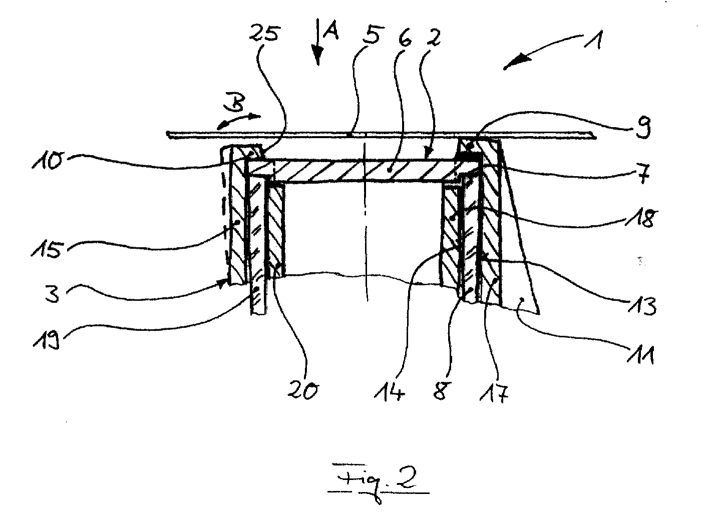
- FIG. 2 there is a corresponding to a section along line X-X in FIG To recognize display device 1 with the housing 3.
- the housing 3 holds a liquid crystal cell 2 with a display area 6 in the viewing direction A by an observer through a transparent area of a Dial 5 can be read through.
- a contact area 7 of the liquid crystal cell 2 is a contacting element 8, which is a Leitgummi is formed, as well as on a corresponding Contacting area of a circuit board, not shown here.
- the contacting element 8 is flat and has a first surface side 13 and a second surface side 14 on which it is guided in the housing 3.
- the contacting element 8 is between an inner side wall 18 and a parallel to this, rigidly connected to the first hook element 9 Side wall 17 of the housing 3 inserted.
- the side wall 17 is with a web 11 stiffened, and the contacting element 8 is between the Printed circuit board and the contact area 7 of the liquid crystal cell 2 clamped.
- a support element 19 between the liquid crystal cell 2 and the printed circuit board tense On the side of the housing opposite the contacting element 8 3 is a support element 19 between the liquid crystal cell 2 and the printed circuit board tense.
- the support element 19 is in the housing 3 between the elastic outer side wall 15 and an inner opposite this Side wall 20 out.
- the side wall 15 faces in one direction B a mobility, so that the liquid crystal cell 2 during assembly the hook element 9 inserted and at the same time pulling back the side wall 15 can be applied to the housing 3, whereupon the liquid crystal cell 2 through the snap-back side wall 15 with the help of second hook element 10 is locked.
- a bevel 25 on the hook element 10 simplifies the joining of liquid crystal cell 2 and housing 3rd
- FIG. 3 Another embodiment of a housing 3 is shown in Figure 3.
- This Housing 3 has a first, trough-shaped housing part 22 with one on the bottom of the housing part 22 located recess 12 and a frame-shaped second housing part 23.
- the first housing part 22 and the second housing part 23 are connected by means of a molded film 24.
- the second Housing part 23 can be inserted into the first housing part 22, of which second housing part 23 inner walls of the housing 3 and of the first Housing part 22 outer walls of the housing 3 are formed.
- a liquid crystal cell is seen from viewing direction A. 2 readable through the recess 12.
- the housing 3 is a single one Component forming with the liquid crystal cell 2 in a contacting area 7 overlapping first hook element 9 and with a liquid crystal cell 2 in an area opposite the contacting area 7 overlapping second hook element 10 provided.
- the hook elements 9, 10 are formed on the first housing part 22 and clamp Contacting element 8 or a support element 19 between the liquid crystal cell 2 and a circuit board 4, which here for the sake of clarity - in a non-final Mounting position - spaced from the contacting element 8 and the support element 19 is shown (the housing parts are in the final position 22, 23 and the contacting element 8 on the circuit board 4).
Landscapes
- Physics & Mathematics (AREA)
- Nonlinear Science (AREA)
- Mathematical Physics (AREA)
- Chemical & Material Sciences (AREA)
- Crystallography & Structural Chemistry (AREA)
- General Physics & Mathematics (AREA)
- Optics & Photonics (AREA)
- Liquid Crystal (AREA)
- Devices For Indicating Variable Information By Combining Individual Elements (AREA)
Abstract
Die Erfindung betrifft eine Anzeigevorrichtung (1), insbesondere in einem Fahrzeug, mit einem an seiner einem Betrachter zugewandten Vorderseite eine Flüssigkristallzelle (2) halternden Gehäuse (3) und mit einer auf der Rückseite des Gehäuses (3) angeordneten Leiterplatte zur elektrischen Kontaktierung der Flüssigkristallzelle (2), wobei zwischen der Leiterplatte und einem außerhalb eines Anzeigebereichs (6) der Flüssigkristallzelle (2) angeordneten Kontaktierungsbereich (7) der Flüssigkristallzelle (2) ein gegen die Flüssigkristallzelle (2) verspanntes, in etwa plattenförmiges und an seinen Flächenseiten (13, 14) in dem Gehäuse (3) geführtes Kontaktierungselement (8) zur elektrischen Verbindung von Leiterplatte und Flüssigkristallzelle (2) angeordnet ist.The invention relates to a display device (1), in particular in a vehicle, with one on its front facing a viewer Liquid crystal cell (2) holding housing (3) and with one on the back of the housing (3) arranged circuit board for electrical contacting the Liquid crystal cell (2), being between the circuit board and an outside a display area (6) of the liquid crystal cell (2) arranged contacting area (7) the liquid crystal cell (2) against the liquid crystal cell (2) braced, approximately plate-shaped and on its flat sides (13, 14) in the housing (3) guided contacting element (8) for electrical connection of circuit board and liquid crystal cell (2) is arranged.
Um die Montage der Anzeigevorrichtung zu vereinfachen, schlägt die Erfindung
vor, daß das Gehäuses (3) ein einziges Bauteil bildend mit einem die Flüssigkristallzelle
(2) im Kontaktierungsbereich (7) übergreifenden ersten Hakenelement
(9) als Gegenhalter für das verspannte Kontaktierungselement (8) und mit
einem die Flüssigkristallzelle (2) in einem dem Kontaktierungsbereich (7) gegenüberliegenden,
außerhalb des Anzeigebereichs (6) der Flüssigkristallzelle
(2) angeordneten Bereich übergreifenden zweiten Hakenelement (10) versehen
ist.
Description
Die Erfindung betrifft eine Anzeigevorrichtung, insbesondere in einem Fahrzeug, mit einem an seiner einem Betrachter zugewandten Vorderseite eine Flüssigkristallzelle halternden Gehäuse und mit einer auf der Rückseite des Gehäuses angeordneten Leiterplatte zur elektrischen Kontaktierung der Flüssigkristallzelle, wobei zwischen der Leiterplatte und einem außerhalb eines Anzeigebereichs der Flüssigkristallzelle angeordneten Kontaktierungsbereich der Flüssigkristallzelle ein gegen die Flüssigkristallzelle verspanntes, in etwa plattenförmiges und an seinen Flächenseiten in dem Gehäuse geführtes Kontaktierungselement zur elektrischen Verbindung von Leiterplatte und Flüssigkristallzelle angeordnet ist.The invention relates to a display device, in particular in a vehicle, with one on its front facing a viewer Liquid crystal cell housing and with one on the back of the Printed circuit board arranged for electrical contacting of the liquid crystal cell, being between the circuit board and an outside of a display area the contacting area of the liquid crystal cell Liquid crystal cell an approximately plate-shaped clamped against the liquid crystal cell and on its flat sides in the housing guided contacting element for the electrical connection of circuit board and liquid crystal cell is arranged.
Derartige Anzeigevorrichtungen sind beispielsweise als Bestandteil von Kombinationsanzeigeinstrumenten in Kraftfahrzeugen bekannt und weit verbreitet. Dabei ist üblicherweise ein die Flüssigkristallzelle niederhaltender und an ihren Seiten einfassender Metallrahmen mit dem die Flüssigkristallzelle halternden Gehäuse oder mit einer Leiterplatte verrastet. Dieses bedeutet einen aufwendigen Montagevorgang, insbesondere das Fügen von Gehäuse, Rahmen und dem in dem Gehäuse zu führenden Kontaktierungselement hat sich als nachteilig vor allem bei Großserienproduktionen - wie sie bei Anwendungen im Kraftfahrzeugbereich erforderlich sind - erwiesen.Such display devices are, for example, part of combination display instruments known and widely used in motor vehicles. In this case, the liquid crystal cell is usually held down and attached to it Metal frame enclosing the sides with the liquid crystal cell Housing or locked with a circuit board. This means an expensive one Assembly process, especially the joining of housing, frame and the contacting element to be guided in the housing has proven to be disadvantageous especially in large series productions - like those in applications in Motor vehicle area are required - proven.
Darüber hinaus ist eine Anzeigevorrichtung mit einer in einem Gehäuse angebrachten Flüssigkristallzelle bekannt, wobei das Gehäuse mit einer Leiterplatte verrastet ist. Zwischen Leiterplatte und Flüssigkristallzelle ist ein kompakter Kontaktstreifen angeordnet. Bei dieser Vorrichtung, die insgesamt eine sehr geringe Höhe aufweist, besteht ein nur minimaler Abstand zwischen Flüssigkristallzelle und Leiterplatte. Dadurch ist einerseits eine Führung des Kontaktstreifens nicht erforderlich; andererseits ist eine Beleuchtung der Flüssigkristallzelle mit üblichen, auf der einem Betrachter abgewandten Rückseite der Flüssigkristallzelle angeordneten Lichtquellen nicht möglich. Für einen Einsatz bei nur geringer Umgebungshelligkeit und damit wenig auf die Flüssigkristallzelle fallendem Auflicht (z. B. bei Umgebungsdunkelheit in Kraftfahrzeugen) ist eine solche Anzeigevorrichtung damit völlig ungeeignet.In addition, there is a display device mounted in a housing Liquid crystal cell known, the housing with a circuit board is locked. There is a compact one between the circuit board and the liquid crystal cell Contact strips arranged. In this device, the overall a very has a low height, there is only a minimal distance between the liquid crystal cell and circuit board. This means that the contact strip is guided on the one hand not mandatory; on the other hand is an illumination of the liquid crystal cell with usual, on the back of the liquid crystal cell facing away from a viewer arranged light sources not possible. For use with only low ambient brightness and therefore little on the liquid crystal cell falling incident light (e.g. in the darkness of the surroundings in motor vehicles) is one such display device completely unsuitable.
Der Erfindung liegt daher die Aufgabe zugrunde, eine Anzeigevorrichtung der eingangs genannten Art zu schaffen, welche Anzeigevorrichtung einfach in Aufbau und Montage und damit für eine Großserienproduktion geeignet ist.The invention is therefore based on the object of a display device to create the type mentioned, which display device simply in Construction and assembly and thus suitable for large series production.
Diese Aufgabe wird erfindungsgemäß dadurch gelöst, daß das Gehäuse ein einziges Bauteil bildend mit einem die Flüssigkristallzelle im Kontaktierungsbereich übergreifenden ersten Hakenelement als Gegenhalter für das verspannte Kontaktierungselement und mit einem die Flüssigkristallzelle in einem dem Kontaktierungsbereich gegenüberliegenden, außerhalb des Anzeigebereichs der Flüssigkristallzelle angeordneten Bereich übergreifenden zweiten Hakenelement versehen ist.This object is achieved in that the housing forming the only component with a liquid crystal cell in the contacting area overlapping first hook element as a counter-holder for the braced Contacting element and with a liquid crystal cell in one Contacting area opposite, outside the display area of the liquid crystal cell arranged area overlapping second hook element is provided.
Mit einer solchen Ausbildung ist die Anzahl der erforderlichen Bauteile für die Anzeigevorrichtung vorteilhaft verringert. Dadurch vereinfacht sich nicht nur ihre Montage, sondern auch Lagerungs- und Handhabungskosten werden gesenkt. Durch das Übergreifen der Flüssigkristallzelle in deren Kontaktierungsbereich sowie in einem diesem Bereich gegenüberliegenden Abschnitt wird mit der erfindungsgemäßen Vorrichtung dauerhaft eine Verspannung des Kontaktierungselementes sichergestellt. Damit ergibt sich über die gesamte Einsatzdauer eine sehr hohe Betriebsicherheit der Anzeige. Dieses ist insbesondere für sicherheitsrelevante Informationen, z. B. Geschwindigkeitsanzeigen in Kraftfahrzeugen, von größter Bedeutung. Darüber hinaus ermöglicht es der Erfindungsgegenstand, bei Bedarf einen im Rahmen üblicher Größenordnungen beliebigen Abstand zwischen Leiterplatte und Flüssigkristallzelle vorzusehen. In dem so geschaffenen Raum können beispielsweise Beleuchtungselemente wie Lichtquellen, Lichtleiter oder Streuscheiben für die Flüssigkristallzelle angeordnet werden. Auch können damit in eine Vielzahl von Anzeigen aufweisenden Anzeigevorrichtungen (z. B. Kombinationsanzeigeinstrumenten für Kraftfahrzeuge) Flüssigkristallzellen eine einheitliche Anzeigeoberfläche mit den weiteren Anzeigen bildend frei plaziert werden. Die erfindungsgemäße Anzeigevorrichtung stellt sicher, daß trotz der permanenten Verspannung des Kontaktierungselements keine Verformung des Gehäuses erfolgt. Die Lage der Flüssigkristallzelle ist damit über die gesamte Lebensdauer gleichbleibend und die elektrische Kontaktierung der Zelle gewährleistet.With such training, the number of components required for Display device advantageously reduced. This not only simplifies yours Assembly, but also storage and handling costs are reduced. By overlapping the liquid crystal cell in its contact area as well as in a section opposite this area, the invention Device permanently tensions the contacting element ensured. This results in the entire period of use very high operational reliability of the display. This is especially for security-relevant information, e.g. B. speed indicators in motor vehicles, of highest importance. In addition, the subject matter of the invention enables if necessary one in the usual order of magnitude provide any distance between the circuit board and the liquid crystal cell. In The space created in this way can be used, for example, as lighting elements Light sources, light guides or diffusers arranged for the liquid crystal cell become. It can also be used in a variety of advertisements Display devices (e.g. combination display instruments for motor vehicles) Liquid crystal cells have a uniform display surface with the others Ads are placed freely forming. The display device according to the invention ensures that despite the permanent tensioning of the contacting element there is no deformation of the housing. The location of the liquid crystal cell is therefore constant over the entire service life and ensures electrical contacting of the cell.
Eine zufriedenstellende Halterung der Flüssigkristallzelle und eine dauerhafte Verspannung des Kontaktierungselements kann bei einer erfindungsgemäßen Anzeigevorrichtung bereits erreicht werden, wenn das erste Hakenelement elastisch mit einer Seitenwandung des Gehäuses verbunden ist. Jedoch wird die Lage der Flüssigkristallzelle auch über einen großen Zeitraum exakt eingehalten und die Verspannung des Kontaktierungselements sichergestellt, wenn gemäß einer vorteilhaften Weiterbildung der Erfindung das erste Hakenelement starr mit einer Seitenwandung des Gehäuses verbunden ist. Von besonderem Vorteil ist es dabei, wenn die Seitenwandung mittels eines Steges versteift ist, so daß Gehäuse und Hakenelement eine z. B. auch bei Temperaturschwankungen feste Anordnung bilden.A satisfactory mounting of the liquid crystal cell and a permanent one The contacting element can be braced in an inventive Display device can already be reached when the first hook element is elastic is connected to a side wall of the housing. However, the The position of the liquid crystal cell is precisely maintained over a long period of time and the tensioning of the contacting element is ensured if according to an advantageous development of the invention, the first hook element is rigidly connected to a side wall of the housing. Of special It is advantageous if the side wall is stiffened by means of a web, so that the housing and hook element a z. B. even with temperature fluctuations form a fixed arrangement.
Man könnte sich ein erstes Hakenelement vorstellen, das den Kontaktierungsbereich der Flüssigkristallzelle lediglich in Abschnitten oder punktuell übergreift. Eine besonders gleichmäßige Druckverteilung und gute Kontaktierung von Flüssigkristallzelle, Kontaktierungselement und Leiterplatte wird hingegen vorteilhaft erreicht, wenn das erste Hakenelement den Kontaktierungsbereich in etwa über dessen gesamte Länge übergreift. One could imagine a first hook element, the contacting area of the liquid crystal cell only in sections or at certain points. A particularly even pressure distribution and good contacting of Liquid crystal cell, contacting element and circuit board, however, is advantageous reached when the first hook element in the contacting area in spans approximately over its entire length.
Gemäß einer anderen vorteilhaften Weiterbildung der Erfindung ist das zweite Hakenelement mit dem Gehäuse in etwa in Richtung der Anzeigeebene der Flüssigkristallzelle eine Elastizität aufweisend verbunden. Auf diese Weise ist die Flüssigkristallzelle besonders einfach in dem Gehäuse montierbar, indem die Zelle hinter das erste Hakenelement einführbar und mittels des zweiten Hakenelements mit dem Gehäuse verrastbar ist.According to another advantageous development of the invention, the second is Hook element with the housing approximately in the direction of the display level Liquid crystal cell connected having an elasticity. That way the liquid crystal cell can be mounted particularly easily in the housing by the cell can be inserted behind the first hook element and by means of the second hook element can be locked with the housing.
Dabei kann das zweite Hakenelement ein einziges Bauteil bildend mit dem Gehäuse verbunden sein, wenn es vorteilhaft an einer elastischen Seitenwandung des Gehäuses angeordnet ist. Damit wird die Bauteilanzahl des Gehäuses verringert und deren Herstellung somit erheblich vereinfacht. Die Elastizität der Seitenwandung des Gehäuses ist vorteilhaft den Aufbau des Gehäuse weiter simplifizierend dadurch zu erzielen, daß das Gehäuse zwei in einer Ebene angeordnete, in etwa senkrecht zur Anzeigeebene der Flüssigkristallzelle verlaufende Schlitze die elastische Seitenwandung bildend aufweist.The second hook element can form a single component with the housing be connected if it is advantageous on an elastic side wall of the housing is arranged. This reduces the number of components in the housing and thus their manufacture is considerably simplified. The elasticity of the Side wall of the housing is advantageous further the structure of the housing to simplify this by making the housing two arranged in one plane, approximately perpendicular to the display plane of the liquid crystal cell Slits forming the elastic side wall.
Eine Führung des Kontaktierungselements in dem Gehäuse könnte beispielsweise durch eine seitliche Anordnung von Stegen oder Armen erreicht werden. Eine besonders exakte Führung, die eine Verwölbung des Kontaktierungselements vermeidet, wodurch eine besonders zuverlässige Kontaktierung von Flüssigkristallzelle, Kontaktierungselement und Leiterplatte erreicht wird, liegt jedoch dann vor, wenn gemäß einer vorteilhaften Weiterbildung der Erfindung das Gehäuse eine äußere Seitenwandung und eine zu dieser in etwa parallele innere Seitenwandung aufweist, zwischen welchen Wandungen das Kontaktierungselement geführt ist.A guidance of the contacting element in the housing could, for example can be achieved by a lateral arrangement of webs or arms. A particularly precise guide that warps the contacting element avoids, whereby a particularly reliable contacting of Liquid crystal cell, contacting element and circuit board is reached however, before if according to an advantageous development of the invention the housing has an outer side wall and an approximately parallel to this Has inner side wall, between which walls the contacting element is led.
Um eine gleichmäßige Abstützung der Flüssigkristallzelle in dem Gehäuse und einen dauerhaften Halt der Zelle sicherzustellen, ist es von Vorteil, wenn an einer dem Kontaktierungselement gegenüberliegenden Seite des Gehäuses ein zwischen der Flüssigkristallzelle und der Leiterplatte verspanntes Stützelement angeordnet ist. To evenly support the liquid crystal cell in the housing and To ensure a permanent hold of the cell, it is an advantage if on a side of the housing opposite the contacting element support element clamped between the liquid crystal cell and the printed circuit board is arranged.
Flüssigkristallzellen sind druckempfindliche Bauelemente, insbesondere Drukkunterschiede über der Anzeigefläche der Zelle können zu störenden Anzeigeverfälschungen führen. Daher ist es gemäß einer anderen vorteilhaften Weiterbildung der Erfindung günstig, wenn das Stützelement und das Kontaktierungselement in etwa gleiche elastische Eigenschaften aufweisen, so daß ein gleichmäßiger Druck auf die Flüssigkristallzelle vorliegt.Liquid crystal cells are pressure-sensitive components, in particular pressure differences Abnormal display falsifications can occur over the display area of the cell to lead. Therefore, it is according to another advantageous development the invention favorable when the support element and the contacting element have approximately the same elastic properties, so that a there is even pressure on the liquid crystal cell.
Der mechanische Aufbau der Anzeigevorrichtung ist dabei besonders stabil und dauerhaltbar, wenn gemäß einer anderen vorteilhaften Weiterbildung der Erfindung das Stützelement in dem Gehäuse zwischen einer äußeren Seitenwandung und einer dieser gegenüberliegenden inneren Seitenwandung des Gehäuses geführt ist.The mechanical structure of the display device is particularly stable and durable if, according to another advantageous development, the Invention the support element in the housing between an outer side wall and one of these opposite inner side wall of the Housing is guided.
Besonders nützlich ist es, wenn das Stützelement elektrisch leitfähig ist. Auf diese Weise kann eine Kontaktierung der Flüssigkristallzelle mit der Leiterplatte nicht nur mittels des Kontaktierungselements, sondern auch zusätzlich mittels des Stützelements zustandegebracht werden.It is particularly useful if the support element is electrically conductive. On in this way, contacting of the liquid crystal cell with the printed circuit board not only by means of the contacting element, but also additionally by means of of the support element can be brought about.
Insbesondere wenn die Anzeigevorrichtung neben der Flüssigkristallzelle weitere Anzeigen, z. B. ein Kombinationsanzeigeinstrument in einem Kraftfahrzeug bildend, aufweist, ist eine sehr exakte Positionierung der Flüssigkristallzelle in dem Gehäuse (und auch gegenüber einem gegebenenfalls vorhandenen Zifferblatt) von großer Bedeutung. Für eine derartige, präzise Positionierung der Flüssigkristallzelle ist es von besonderem Vorteil, wenn gemäß einer anderen Weiterbildung der Erfindung das Gehäuse gegenüberliegende, die Flüssigkristallzelle an nicht von einem Hakenelement übergriffenen Seiten führende Stege aufweist.Especially when the display device in addition to the liquid crystal cell Ads, e.g. B. a combination display instrument in a motor vehicle forming, is a very exact positioning of the liquid crystal cell in the case (and also in relation to an existing dial) of great importance. For such a precise positioning of the Liquid crystal cell, it is particularly advantageous if according to another Further development of the invention, the housing opposite, the liquid crystal cell on webs not leading from a hook element having.
Besonders kostengünstig auch in großer Stückzahl herstellbar und einfach handhabbar ist das Kontaktierungselement und/oder das Stützelement, wenn es ein Leitgummi ist. Particularly inexpensive to manufacture in large numbers and simple the contacting element and / or the support element can be handled if it is a guiding rubber.
Das Gehäuse könnte aus mehreren Elementen zusammengebaut und/oder beispielsweise als gekantetes und gebogenes Metallbauteil ausgebildet sein. Jedoch ist es gemäß einer anderen Weiterbildung der Erfindung besonders vorteilhaft, wenn das Gehäuse ein Kunststoffspritzgußbauteil ist. Damit kann das Gehäuse in einem einzigen Arbeitsgang ein einziges Bauteil mit den Haken- und Stützelementen sowie den Wandungen bildend hergestellt werden. Außerdem ist es damit vorteilhaft möglich, das Gehäuse in Form eines Mittelgehäuses für ein Kombinationsanzeigeinstrument - Aufnahmen- und/oder Lichtführungen und/oder Halterungen für weitere Anzeigeelemente aufweisend - auszubilden.The housing could be assembled from several elements and / or be designed, for example, as a bent and bent metal component. However, according to another development of the invention, it is special advantageous if the housing is a plastic injection molded component. So that can the housing is a single component with the hook and supporting elements and the walls are formed. It is also advantageously possible to have the housing in the form of a central housing for a combination display instrument - recording and / or Having light guides and / or brackets for further display elements - train.
Gemäß einer anderen vorteilhaften Weiterbildung der Erfindung ist das Gehäuse zweiteilig, wobei das erste Gehäuseteil äußere Gehäusewandungen und das zweite, in das erste Gehäuseteil einfügbare Gehäuseteil innere Gehäusewandungen aufweist, wodurch Gehäuseteile einfacher Geometrie besonders leicht erzielbar sind. Die Geometrie des Gehäuses wird dabei ebenso wie der Zusammenbau der Anzeigevorrichtung weiter vereinfacht, wenn gemäß einer anderen vorteilhaften Weiterbildung der Erfindung im Bereich des Kontaktierungselements und/oder des Stützelements der Abstand zwischen der inneren und der äußeren Gehäusewandung jeweils in etwa der Dicke des Kontaktierungselements und/oder des Stützelements entspricht.According to another advantageous development of the invention, the housing is two parts, the first housing part outer housing walls and the second housing part, which can be inserted into the first housing part, has inner housing walls has, whereby housing parts of simple geometry particularly are easy to achieve. The geometry of the housing is just like that Assembly of the display device further simplified if according to one another advantageous development of the invention in the area of the contacting element and / or the support element, the distance between the inner and the outer housing wall in each case approximately the thickness of the contacting element and / or the support element corresponds.
Dabei ist es für die Lagerhaltung und das Handling der Gehäuseteile vor der Montage der Anzeigevorrichtung von großem Vorteil, wenn das erste Gehäuseteil und das zweite Gehäuseteil ein einziges Bauteil bildend miteinander verbunden sind. Jeweils zueinander gehörige Gehäuseteile sind auf diese Weise nicht nur automatisch einander zugeordnet, sondern auch unverlierbar miteinander verbunden. Die Verbindung behindert die Montage des Gehäuses nicht und beansprucht ein nur geringes Werkstoffvolumen, wenn vorteilhaft das erste Gehäuseteil und das zweite Gehäuseteil mit einem Film verbunden sind. Derartig verbundene Gehäuseteile sind in besonders einfacher Weise auch im Kunststoffspritzgießverfahren herstellbar, wobei der Film eine ein einziges Bauteil bildend mit den Gehäuseteilen verbundene Kunststoffolie ist.It is for the storage and handling of the housing parts before Mounting the display device is of great advantage when the first housing part and the second housing part is connected to one another to form a single component are. Corresponding housing parts are in this way not only automatically assigned to each other, but also captive to each other connected. The connection does not hinder the assembly of the housing and requires only a small volume of material, if advantageous the first Housing part and the second housing part are connected with a film. Such connected housing parts are also in a particularly simple manner Plastic injection molding process can be produced, the film being a single Component forming plastic film connected to the housing parts.
Die Erfindung wird im folgenden anhand von in der beifügten Zeichnung dargestellten Ausführungsbeispielen näher erläutert. Es zeigt
- Fig. 1
- ein Gehäuse einer erfindungsgemäßen Anzeigevorrichtung in perspektivischer Ansicht,
- Fig. 2
- einen Vertikalschnitt durch die Anzeigevorrichtung mit dem Gehäuse nach Fig. 1,
- Fig. 3
- ein weiteres Gehäuse in einer geschnittenen Seitenansicht und
- Fig. 4
- das Gehäuse nach Fig. 3 mit einer darin eingesetzten Flüssigkristallzelle.
- Fig. 1
- a housing of a display device according to the invention in perspective view,
- Fig. 2
- 2 shows a vertical section through the display device with the housing according to FIG. 1,
- Fig. 3
- another housing in a sectional side view and
- Fig. 4
- 3 with a liquid crystal cell used therein.
Figur 1 zeigt ein als Kunststoffspritzgußbauteil ausgebildetes Gehäuse 3 einer
hier nicht weiter dargestellten Anzeigevorrichtung eines Kraftfahrzeugs. Das
Gehäuse 3 weist einen kastenförmigen Aufbau mit einem an einer Langseite
des Gehäuses 3 angeordneten ersten Hakenelement 9 und einem, dem ersten
Hakenelement 9 gegenüberliegenden, zweiten Hakenelement 10 auf. An den
Schmalseiten des Gehäuses 3 sind Stege 21 angeordnet, von denen einer zum
Ausgleich von Fertigungstoleranzen federnd ausgeführt ist. Das zweite Hakenelement
10 ist an einer ebenfalls federnden, elastischen Seitenwandung 15
des Gehäuses 3 angeordnet. Die Federeigenschaft der Seitenwandung 15 wird
dabei durch vertikale Schlitze 16 erreicht, die die Seitenwandung 15 seitlich
von dem Gehäuse 3 trennen.FIG. 1 shows a
In Figur 2 ist entsprechend einem Schnitt entlang Linie X - X in Figur 1 eine
Anzeigevorrichtung 1 mit dem Gehäuse 3 zu erkennen. Das Gehäuse 3 haltert
eine Flüssigkristallzelle 2 mit einem Anzeigebereich 6, der in Betrachtungsrichtung
A von einem Beobachter durch einen transparenten Bereich eines
Zifferblattes 5 hindurch abgelesen werden kann. An einem Kontaktierungsbereich
7 der Flüssigkristallzelle 2 liegt ein Kontaktierungselement 8, das von einem
Leitgummi gebildet wird, ebenso an wie an einem korrespondierenden
Kontaktierungsbereich einer hier nicht dargestellten Leiterplatte. Das Kontaktierungselement
8 ist flächig ausgebildet und weist eine erste Flächenseite 13 und
eine zweite Flächenseite 14 auf, an denen es in dem Gehäuse 3 geführt ist.
Dazu ist das Kontaktierungselement 8 zwischen eine innere Seitenwandung 18
und eine zu dieser parallele, starr mit dem ersten Hakenelement 9 verbundene
Seitenwandung 17 des Gehäuses 3 eingelegt. Die Seitenwandung 17 ist mit
einem Steg 11 versteift, und das Kontaktierungselement 8 ist zwischen der
Leiterplatte und dem Kontaktierungsbereich 7 der Flüssigkristallzelle 2 verspannt.In FIG. 2 there is a corresponding to a section along line X-X in FIG
To recognize
An der dem Kontaktierungselement 8 gegenüberliegenden Seite des Gehäuses
3 ist zwischen der Flüssigkristallzelle 2 und der Leiterplatte ein Stützelement 19
verspannt. Das Stützelement 19 ist in dem Gehäuse 3 zwischen der elastischen
äußeren Seitenwandung 15 und einer dieser gegenüberliegenden inneren
Seitenwandung 20 geführt. Die Seitenwandung 15 weist in einer Richtung
B eine Beweglichkeit auf, so daß die Flüssigkristallzelle 2 bei der Montage unter
das Hakenelement 9 eingeschoben und bei gleichzeitigem Zurückziehen
der Seitenwandung 15 an das Gehäuse 3 anlegbar ist, woraufhin die Flüssigkristallzelle
2 durch die zurückschnappende Seitenwandung 15 mit Hilfe des
zweiten Hakenelements 10 verrastet wird. Eine Abschrägung 25 an dem Hakenelement
10 vereinfacht dabei das Fügen von Flüssigkristallzelle 2 und Gehäuse
3.On the side of the housing opposite the contacting
Eine weitere Ausführungsform eines Gehäuses 3 ist in Figur 3 dargestellt. Dieses
Gehäuse 3 weist ein erstes, trogförmiges Gehäuseteil 22 mit einer am Boden
des Gehäuseteils 22 befindlichen Ausnehmung 12 sowie ein rahmenförmiges
zweites Gehäuseteil 23 auf. Das erste Gehäuseteil 22 und das zweite Gehäuseteil
23 sind mittels eines angespritzten Films 24 verbunden. Das zweite
Gehäuseteil 23 ist in das erste Gehäuseteil 22 einfügbar, wobei von dem
zweiten Gehäuseteil 23 innere Wandungen des Gehäuses 3 und von dem ersten
Gehäuseteil 22 äußere Wandungen des Gehäuses 3 gebildet werden.Another embodiment of a
Wie Figur 4 zu entnehmen, ist aus Betrachtungsrichtung A eine Flüssigkristallzelle
2 durch die Ausnehmung 12 ablesbar. Das Gehäuse 3 ist ein einziges
Bauteil bildend mit einem die Flüssigkristallzelle 2 in einem Kontaktierungsbereich
7 übergreifenden ersten Hakenelement 9 und mit einem die Flüssigkristallzelle
2 in einem dem Kontaktierungsbereich 7 gegenüberliegenden Bereich
übergreifenden zweiten Hakenelement 10 versehen. Die Hakenelemente 9, 10
sind dabei an dem ersten Gehäusesteil 22 ausgebildet und verspannen ein
Kontaktierungselement 8 bzw. ein Stützelement 19 zwischen Flüssigkristallzelle
2 und einer Leiterplatte 4, die hier der Deutlichkeit halber - in einer nicht endgültigen
Montageposition - beabstandet von dem Kontaktierungselement 8 und
dem Stützelement 19 dargestellt ist (in der endgültigen Position liegen die Gehäuseteile
22, 23 und das Kontaktierungselement 8 an der Leiterplatte 4 an).As can be seen in FIG. 4, a liquid crystal cell is seen from viewing direction A.
2 readable through the
Es ist zu erkennen, daß Flächenseiten 13, 14 des Kontaktierungselements 8 in
dem Gehäuse 3 zwischen den Gehäusesteilen 22, 23 geführt sind. Nach dem
Fügen kontaktiert das Kontaktierungselement 8 den Kontaktierungsbereich 7
der Flüssigkristallzelle 2 mit einem Kontaktierungsbereich 26 der Leiterplatte 4.
Der die Gehäuseteile 22, 23 verbindende Film 24, der als schmaler Streifen
seitlich neben dem Kontaktierungselement 8 angeordnet ist, wird den Zusammenbau
nicht störend zwischen Gehäuse 3 und Leiterplatte 4 eingequetscht.It can be seen that surface sides 13, 14 of the contacting
Claims (19)
Applications Claiming Priority (2)
| Application Number | Priority Date | Filing Date | Title |
|---|---|---|---|
| DE10010812 | 2000-03-08 | ||
| DE10010812A DE10010812A1 (en) | 2000-03-08 | 2000-03-08 | Display device has housing forming single part with hook element engaging cell in contact region, second hook element engaging cell in region outside display region, opposite contact region |
Publications (3)
| Publication Number | Publication Date |
|---|---|
| EP1136870A2 true EP1136870A2 (en) | 2001-09-26 |
| EP1136870A3 EP1136870A3 (en) | 2003-10-22 |
| EP1136870B1 EP1136870B1 (en) | 2006-10-04 |
Family
ID=7633658
Family Applications (1)
| Application Number | Title | Priority Date | Filing Date |
|---|---|---|---|
| EP01103943A Expired - Lifetime EP1136870B1 (en) | 2000-03-08 | 2001-02-19 | Displaying device |
Country Status (3)
| Country | Link |
|---|---|
| US (1) | US20020036727A1 (en) |
| EP (1) | EP1136870B1 (en) |
| DE (2) | DE10010812A1 (en) |
Families Citing this family (2)
| Publication number | Priority date | Publication date | Assignee | Title |
|---|---|---|---|---|
| DE10322973B3 (en) * | 2003-05-21 | 2004-10-14 | Siemens Ag | Overvoltage diversion arrangement for electronic device e.g. display device in automobile, uses slit in side edge of fixing lug for electrically-conductive housing for contacting earthed contact surface |
| CN103065562A (en) * | 2011-10-18 | 2013-04-24 | 上海江森自控汽车电子有限公司 | Automobile meter liquid crystal display |
Family Cites Families (8)
| Publication number | Priority date | Publication date | Assignee | Title |
|---|---|---|---|---|
| US4367467A (en) * | 1981-01-30 | 1983-01-04 | Sangamo Weston, Inc. | LCD Display mount window |
| DE3726225C1 (en) * | 1987-08-07 | 1988-08-04 | Telefonbau & Normalzeit Gmbh | Display device with a liquid crystal display |
| DE4105505A1 (en) * | 1991-02-22 | 1992-09-03 | Telefonbau & Normalzeit Gmbh | Liquid crystal display device with large number of electrode connections - uses distance piece to separate compressable conducting blocks, enabling two rows of connections to be employed |
| DE9109166U1 (en) * | 1991-07-25 | 1991-09-19 | Grundig E.M.V. Elektro-Mechanische Versuchsanstalt Max Grundig holländ. Stiftung & Co KG, 8510 Fürth | Device for attaching an LC display to a circuit board |
| JP3231820B2 (en) * | 1991-12-17 | 2001-11-26 | ソニー株式会社 | Liquid crystal display |
| DE19740424A1 (en) * | 1997-09-10 | 1999-03-11 | Mannesmann Vdo Ag | Dashboard display device for automobile using liquid crystal cell |
| JP3728981B2 (en) * | 1998-08-26 | 2005-12-21 | セイコーエプソン株式会社 | Liquid crystal device and electronic device |
| DE29902903U1 (en) * | 1999-02-18 | 1999-05-12 | Huang, Rei-Chung, Yungho | Liquid crystal display device with a replaceable base plate |
-
2000
- 2000-03-08 DE DE10010812A patent/DE10010812A1/en not_active Withdrawn
-
2001
- 2001-02-19 EP EP01103943A patent/EP1136870B1/en not_active Expired - Lifetime
- 2001-02-19 DE DE50111120T patent/DE50111120D1/en not_active Expired - Lifetime
- 2001-03-06 US US09/801,195 patent/US20020036727A1/en not_active Abandoned
Also Published As
| Publication number | Publication date |
|---|---|
| EP1136870B1 (en) | 2006-10-04 |
| DE50111120D1 (en) | 2006-11-16 |
| DE10010812A1 (en) | 2001-09-13 |
| US20020036727A1 (en) | 2002-03-28 |
| EP1136870A3 (en) | 2003-10-22 |
Similar Documents
| Publication | Publication Date | Title |
|---|---|---|
| DE69109088T2 (en) | Electronic instrument with shielding device. | |
| DE102005015973B4 (en) | Fastening device for at least one sensor on a vehicle window | |
| EP0013335A1 (en) | Arrangement for electrically connecting a multiplicity of contacts | |
| DE19632381A1 (en) | Combination instrument | |
| DE2314416C3 (en) | Fastening device | |
| DE2722388A1 (en) | PASSIVE ELECTRO-OPTICAL INDICATOR | |
| DE102015109663A1 (en) | Light emitting device and mobile object | |
| DE3226972C2 (en) | ||
| DE4236353C2 (en) | Electrical assembly | |
| DE3326972C2 (en) | ||
| EP1136870B1 (en) | Displaying device | |
| EP0695964A2 (en) | Indication apparatus with electrooptic cell for vehicle dashboard | |
| DE19740424A1 (en) | Dashboard display device for automobile using liquid crystal cell | |
| DE102018118058A1 (en) | Head-up display with a specific holding clip for holding a mirror | |
| DE60203556T2 (en) | component carrier | |
| DE3144535C2 (en) | Display device with liquid crystal display | |
| DE8902173U1 (en) | Optical display device with fluorescent tube | |
| DE2851998C2 (en) | Illuminated installation switch | |
| DE9300661U1 (en) | Housing for an electronic device | |
| DE9106714U1 (en) | Assembly of several mounting plates arranged in parallel planes | |
| DE8712960U1 (en) | Translucent plastic film part for protecting display elements | |
| CH673161A5 (en) | ||
| DE102008053590B4 (en) | Display device, in particular for a vehicle | |
| DE102020122745B4 (en) | Stabilizer bracket and stabilizer system bracket assembly for stabilizing a keyboard keycap, stabilizer kit and keyboard | |
| EP0703482A1 (en) | Display device with spaced cells |
Legal Events
| Date | Code | Title | Description |
|---|---|---|---|
| PUAI | Public reference made under article 153(3) epc to a published international application that has entered the european phase |
Free format text: ORIGINAL CODE: 0009012 |
|
| AK | Designated contracting states |
Kind code of ref document: A2 Designated state(s): AT BE CH CY DE DK ES FI FR GB GR IE IT LI LU MC NL PT SE TR |
|
| AX | Request for extension of the european patent |
Free format text: AL;LT;LV;MK;RO;SI |
|
| RAP1 | Party data changed (applicant data changed or rights of an application transferred) |
Owner name: SIEMENS AKTIENGESELLSCHAFT |
|
| PUAL | Search report despatched |
Free format text: ORIGINAL CODE: 0009013 |
|
| AK | Designated contracting states |
Kind code of ref document: A3 Designated state(s): AT BE CH CY DE DK ES FI FR GB GR IE IT LI LU MC NL PT SE TR |
|
| AX | Request for extension of the european patent |
Extension state: AL LT LV MK RO SI |
|
| 17P | Request for examination filed |
Effective date: 20031217 |
|
| AKX | Designation fees paid |
Designated state(s): DE FR GB |
|
| GRAP | Despatch of communication of intention to grant a patent |
Free format text: ORIGINAL CODE: EPIDOSNIGR1 |
|
| GRAS | Grant fee paid |
Free format text: ORIGINAL CODE: EPIDOSNIGR3 |
|
| GRAA | (expected) grant |
Free format text: ORIGINAL CODE: 0009210 |
|
| AK | Designated contracting states |
Kind code of ref document: B1 Designated state(s): DE FR GB |
|
| REG | Reference to a national code |
Ref country code: GB Ref legal event code: FG4D Free format text: NOT ENGLISH |
|
| REF | Corresponds to: |
Ref document number: 50111120 Country of ref document: DE Date of ref document: 20061116 Kind code of ref document: P |
|
| GBT | Gb: translation of ep patent filed (gb section 77(6)(a)/1977) |
Effective date: 20061122 |
|
| ET | Fr: translation filed | ||
| PLBE | No opposition filed within time limit |
Free format text: ORIGINAL CODE: 0009261 |
|
| STAA | Information on the status of an ep patent application or granted ep patent |
Free format text: STATUS: NO OPPOSITION FILED WITHIN TIME LIMIT |
|
| 26N | No opposition filed |
Effective date: 20070705 |
|
| REG | Reference to a national code |
Ref country code: FR Ref legal event code: TP |
|
| REG | Reference to a national code |
Ref country code: GB Ref legal event code: 732E Free format text: REGISTERED BETWEEN 20110825 AND 20110831 |
|
| PGFP | Annual fee paid to national office [announced via postgrant information from national office to epo] |
Ref country code: GB Payment date: 20120221 Year of fee payment: 12 |
|
| GBPC | Gb: european patent ceased through non-payment of renewal fee |
Effective date: 20130219 |
|
| PG25 | Lapsed in a contracting state [announced via postgrant information from national office to epo] |
Ref country code: GB Free format text: LAPSE BECAUSE OF NON-PAYMENT OF DUE FEES Effective date: 20130219 |
|
| REG | Reference to a national code |
Ref country code: FR Ref legal event code: PLFP Year of fee payment: 15 |
|
| REG | Reference to a national code |
Ref country code: DE Ref legal event code: R084 Ref document number: 50111120 Country of ref document: DE |
|
| REG | Reference to a national code |
Ref country code: DE Ref legal event code: R084 Ref document number: 50111120 Country of ref document: DE Effective date: 20150227 |
|
| PGFP | Annual fee paid to national office [announced via postgrant information from national office to epo] |
Ref country code: FR Payment date: 20150219 Year of fee payment: 15 |
|
| REG | Reference to a national code |
Ref country code: FR Ref legal event code: ST Effective date: 20161028 |
|
| PG25 | Lapsed in a contracting state [announced via postgrant information from national office to epo] |
Ref country code: FR Free format text: LAPSE BECAUSE OF NON-PAYMENT OF DUE FEES Effective date: 20160229 |
|
| PGFP | Annual fee paid to national office [announced via postgrant information from national office to epo] |
Ref country code: DE Payment date: 20200229 Year of fee payment: 20 |
|
| REG | Reference to a national code |
Ref country code: DE Ref legal event code: R071 Ref document number: 50111120 Country of ref document: DE |