EP1136854A2 - Non-reflection optical fiber termination and method of manufacturing the same - Google Patents
Non-reflection optical fiber termination and method of manufacturing the same Download PDFInfo
- Publication number
- EP1136854A2 EP1136854A2 EP01101106A EP01101106A EP1136854A2 EP 1136854 A2 EP1136854 A2 EP 1136854A2 EP 01101106 A EP01101106 A EP 01101106A EP 01101106 A EP01101106 A EP 01101106A EP 1136854 A2 EP1136854 A2 EP 1136854A2
- Authority
- EP
- European Patent Office
- Prior art keywords
- optical fiber
- reflection
- fusion splicing
- termination according
- core
- Prior art date
- Legal status (The legal status is an assumption and is not a legal conclusion. Google has not performed a legal analysis and makes no representation as to the accuracy of the status listed.)
- Withdrawn
Links
Images

Classifications
-
- G—PHYSICS
- G02—OPTICS
- G02B—OPTICAL ELEMENTS, SYSTEMS OR APPARATUS
- G02B6/00—Light guides; Structural details of arrangements comprising light guides and other optical elements, e.g. couplings
- G02B6/24—Coupling light guides
- G02B6/241—Light guide terminations
-
- G—PHYSICS
- G02—OPTICS
- G02B—OPTICAL ELEMENTS, SYSTEMS OR APPARATUS
- G02B6/00—Light guides; Structural details of arrangements comprising light guides and other optical elements, e.g. couplings
- G02B6/24—Coupling light guides
- G02B6/255—Splicing of light guides, e.g. by fusion or bonding
- G02B6/2551—Splicing of light guides, e.g. by fusion or bonding using thermal methods, e.g. fusion welding by arc discharge, laser beam, plasma torch
Definitions
- the present invention relates to a non-reflection optical fiber termination and a method of manufacturing the non-reflection optical fiber termination for suppressing light reflection at the terminal part of an optical fiber.
- non-reflection optical fiber termination e.g., the non-reflection termination of an optical fiber to be coupled to a coupler used for an optical amplifier, for example.
- non-reflection treatment techniques to terminate the terminal part of the optical fiber so that no reflection of light occurs thereat. Examples of those techniques are oblique polishing, spherical surface forming polishing, and covering by apolymer, phosphorus, nickel or the like. A further example uses light-absorbing material.
- the present invention has an object to provide a non-reflection optical fiber termination and a method of manufacturing the non-reflection optical fiber termination which has a large reflection attenuation quantity.
- a non-reflection optical fiber termination comprising: a first optical fiber; a second optical fiber coupled to an end portion of the first fiber at one end portion, and non-reflection-treated at the other end portion; and a fused splicing part where the end portion of the first optical fiber and the one end portion of the second optical fiber are fusion spliced together so as to substantially have a coupling loss.
- the first and second optical fiber are fusion spliced in a state that a core axis of the first optical fiber is shifted away from that of the second optical fiber.
- anoffset quantity between the core axes of the first and second optical fibers may be not less than 3/4 times a mode field diameter.
- the first and second optical fibers are different in core diameter.
- one of the first and second optical fibers is expanded in core diameter.
- the second optical fiber is an optical fiber (referred to as a third optical fiber) configured to have substantially a transmission loss.
- the third optical fiber may be an optical fiber not including a core.
- the third optical fiber may be also an optical fiber which greatly attenuates optical power of light propagating therethrough.
- a non-reflection optical fiber termination comprising: a first optical fiber; a second optical fiber having substantially a transmission loss, the second optical fiber coupled to an end portion of the first fiber at one end portion and non-reflection-treated at the other end portion; and a fused splicing part where the end portion of the first optical fiber and the one end portion of the second optical fiber are fusion spliced together.
- the second optical fiber is an optical fiber which greatly attenuates optical power of light propagating therethrough.
- the optical fiber to be terminated with no reflection and having substantially a transmission loss may be an optical fiber not including a core.
- the object can be achieved by a method of manufacturing a non-reflection optical fiber termination, according to a third aspect of the present invention, comprising: fusion splicing a first optical fiber and a second optical fiber together so as to substantially have a coupling loss; and non-reflection treating the second optical fiber.
- the above-mentioned object can be also achieved by a method of manufacturing a non-reflection optical fiber termination, according to a fourth aspect of the present invention, comprising: fusion splicing a first optical fiber and a second optical fiber together; and non-reflection treating the second optical fiber.
- Fig. 1 is a diagram showing a first embodiment of a non-reflection optical fiber termination according to the present invention.
- reference numerals 1, 2, 3, ... , n are optical fibers; 1a, 2a, 3a, .. na are cores; 1b, 2b, 3b, ..., nb are clad layers; 1c, 2c, ... are fusion splicing parts; and 10 is a non-reflection treating parts.
- an optical fiber 1 is treated for non-reflection.
- the terminal part of the optical fiber 1 is treated by a non-reflection terminating technique appropriately selected from among those techniques as mentioned above.
- an optical fiber 2 is joined to the optical fiber 1 in an end-to-end fashion, and fusion spliced together. In fusion-splicing those optical fibers, a core 1a of the optical fiber 1 is joined to a core 2a of the subsequent optical fiber 2 in a state that those cores are axially shifted away from each other.
- the axis of the core 1a is shifted, by an offset quantity D, from the axis of the core 2a in splicing them together. Therefore, when light propagates from the optical fiber 1 to the optical fiber 2, the light is attenuated in power at the axis-offset fusion splicing part 1c and reaches the optical fiber 2. Accordingly, a coupling loss occurs at the fusion splicing part.
- part of light coming in through the core 1a enters the core 2a, while the remaining part of it enters the clad layer 2b. The light entering the clad layer 2b can not pass through the clad layer 2b, and leaks out of the optical fiber 2.
- the quantity of the reflected light at a fusion splicing part is less than -75 dB.
- a coupling loss at a fusion splicing part is not more than 0.25 dB. If such the optical fibers are fusion spliced in such a manner that core axes of the optical fibers are shifted apart from each other or the optical fibers which are different in core diameter are fusion spliced together, the coupling loss can be increased. In this case, the substantial coupling loss may be not less than 0.5 dB.
- the light power loss may be not less than 5dB at the fusion splicing part if the offset quantity D is not less than 3/4 times the mode field diameter.
- optical fibers 1 to n are sequentially spliced at "n-1" number of fusion splicing parts such that the optical fiber 2 is joined end to end and fusion spliced to the optical fiber 1 to be non-reflection terminated, while being axially shifted apart from each other (fusion splicing part 1c), the optical fiber 3 is joined end to end and fusion spliced to the optical fiber 2, while being axially shifted apart from each other (fusion splicing part 2c), and so on. If the coupling loss is 5dB at one fusion splicing part, the back reflection light is attenuated 5dB at the fusion splicing part when it travels from the optical fiber 2 to the optical fiber 1.
- the back reflection light undergoes the coupling loss of 10dB when it travels forward and backward passing through one fusion splicing part. This indicates that the reflection attenuation quantity is increased 10dB.
- the MFD of the SN optical fiber is approximately 10 ⁇ m. Accordingly, if the offset quantity at the fusion splicing part is approximately 7.5 ⁇ m, the back reflection light can be attenuated by about 10dB at one fusion splicing part. Therefore, if a plurality of fusion splicing parts where the optical fibers are joined and fusion spliced in an end-to-end fashion while being axially shifted from each other are provided, the coupling loss will be more increased.
- the reflection attenuation quantity is 40dB at a non-reflection treating part 10 of the terminal part of the final optical fiber of those serially spliced optical fibers.
- the optical fiber 2 is the final optical fiber and the terminal part of the optical fiber 2 is non-reflection-treated, the reflection attenuation quantity of 50dB is obtained.
- two axis-offset fusion splicing parts are provided, viz., in the case of Fig.
- the optical fiber 3 is the final optical fiber and the terminal part of the optical fiber 3 is non-reflection-treated, the reflection attenuation quantity of 60dB is obtained. Accordingly, the reflection attenuation quantity of 70dB or larger can be secured if three or more number of the fusion splicing parts are provided. A satisfactory reflection attenuation quantity is more effectively achieved if the coupling loss at one fusion splicing part is selected to be at least 5dB.
- the lengths of the optical fibers 2, 3, .., n, which are subsequent to the optical fiber 1, may be properly selected, and may be selected in consideration of the efficiency of fusion splicing work.
- the non-reflection treating part 10 of the final optical fiber may take an appropriate structure.
- the terminal part of the final optical fiber may be covered with a polymer.
- This non-reflection treatment is disclosed in Japanese Patent Unexamined Publication No. Hei.9-5545.
- the end part of the optical fiber is cut or ruptured by pressure, and is carried out by burying the end part of the optical fiber in an ethylene-vinyl acetate copolymer or the modified product or the mixture heated at equal to or above the melting point and solidifying under cooling.
- the reflection attenuation of light attains to a value of about 40dB.
- non-reflection treatment is based on the spherical surface shaping process. It is disclosed also in Japanese Patent Unexamined Publication No. Hei. 8-262229 and Japanese Patent Unexamined Publication No. Hei. 11-72622.
- the terminal part of the optical fiber is spherically shaped by heating and melting terminal part.
- the spherical surface may also be shaped by heating the terminal part so as to diffuse dopant thereinto.
- the reflection attenuation quantity attains to a value of about 60dB.
- non-reflection treating part is a structure in which the end face of the optical fiber is obliquely polished, a structure in which the end part of the optical fiber is obliquely ruptured by pressure and coated with resin whose refractive index is approximate to that of the core of the optical fiber, a structure in which the end part of the optical fiber is bent, and others.
- any of those structures of the non-reflection treating part may be employed for the non-reflection treatment applied to the final optical fiber.
- the coupling loss at the fusion splicing part further contributes to the increase of the reflection attenuation. Therefore, a desired quantity of the reflection attenuation can easily be secured.
- Fig. 2 is a diagram showing a second embodiment of a non-reflection optical fiber termination according to the present invention.
- like or equivalent portions are designated by like reference numerals in Fig. 1.
- reference numerals 11, 12, ..., 1n designate optical fibers.
- the core diameter of the optical fiber 11, which is to be fusion spliced to the optical fiber 1, is different from that of the optical fiber 1.
- the optical fiber 1 is a single mode optical fiber of 5 ⁇ m in core diameter
- the optical fiber 11 is a multi-mode optical fiber of 50 ⁇ m in core diameter.
- the fusion splicing part lc part of the back reflection light enters from the optical fiber 11 of the large core diameter to the optical fiber 1 of the small core diameter, while the remaining part of the back reflection light enters the clad layer.
- the core diameter of the optical fiber 12 is smaller than that of the optical fiber 11.
- the core diameter of the optical fiber 12 may be selected to be larger than that of the optical fiber 11, as a matter of course.
- the coupling loss of light may be caused when light travels from the optical fiber of the large core diameter to the optical fiber of the small core diameter.
- the terminal end of the final optical fiber of those serially spliced optical fibers is treated so that light is not reflected thereat.
- the optical fibers 11, 12, ..., 1n, which are subsequent to the optical fiber 1 maybe properly selected in length, and in the length selection, the efficiency of fusion splicing work may be taken into account.
- the optical fiber of this embodiment may be a ring core optical fiber having a ring-like large refractive index, as shown in Fig. 3. It is readily understood that the ring core optical fiber may also be used in the first embodiment.
- the abscissa represents the radius r measured from the center O
- the ordinate represents a refractive index difference ⁇ n.
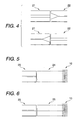
- Figs. 4A-B are respectively diagrams showing a third embodiment of a non-reflection optical fiber termination according to the present invention.
- 21 and 22 are optical fibers.
- the optical fiber 22 is fusion spliced to the optical fiber 21 in the terminal end direction.
- the terminal part of one of the optical fibers at the fusion splicing part is configured such that the core diameter thereof is enlarged toward its end face.
- the core diameter may be enlarged by heating the end part of the optical fiber and diffusing dopant thereinto.
- the core diameter of the end part of the optical fiber 22 is enlarged toward the end face thereof.
- the core diameter of the end part of the optical fiber 21 is enlarged toward the end face thereof.
- the coupling loss occurs in one way of light traveling, as in the second embodiment.
- the optical fiber 21 may be the optical fiber 1 described in connection with Fig. 1 or any of the optical fiber 2 and the subsequent ones, which is also described in Fig. 1.
- the optical fiber 22 is fusion spliced to the optical fiber 21.
- the terminal end of the final optical fiber is non-reflection-treated.
- the optical fibers which are subsequent in connection to the optical fiber 1 may be properly selected in length, and in the length selection, the efficiency of fusion splicing work may be taken into account.
- Fig. 5 is a diagram showing a fourth embodiment of a non-reflection optical fiber termination according to the present invention.
- like or equivalent portions are designated by like reference numerals in Fig. 1.
- reference numeral 23 is an optical fiber
- numeral 24 is a coreless optical fiber 24.
- the coreless optical fiber 24 is used for the final optical fiber as the optical fiber to be non-reflection-treated. It is preferable that a refractive index of the coreless optical fiber 24 is nearly equal to or smaller than that of the core of the optical fiber 23. Light coming from the optical fiber 23 reaches the terminal end of the coreless optical fiber 24 while leaking outside during the course of its propagation through the optical fiber. The light reaching the terminal end is little reflected at the non-reflection treating part 10, so the back reflection-light therefrom is very small in amount. Further, the back reflection light leaks outside when it returns through the coreless optical fiber 24, and therefore the light enter ing the core of the optical fiber 23 is extremely small in amount. If the outer surface of the coreless optical fiber 24 is covered with a material whose refractive index is larger than that of the coreless optical fiber 24, light passing through the coreless optical fiber 24 is easy to leak outside. The result is to reduce the back reflection light in amount.
- the coreless optical fiber 24 of this embodiment may be used for the final optical fiber in each of the first to third embodiments. If required, it may be fusion spliced to the optical fiber 1 in any of those embodiments. Incidentally, a length of the coreless optical fiber 24 is selected so that a desired attenuation quantity is obtained.
- Fig. 6 is a diagram showing a fifth embodiment of a non-reflection optical fiber termination according to the present invention.
- like or equivalent portions are designated by like reference numerals in Figs. 1 and 5.
- reference numeral 25 is an optical fiber having large attenuation.
- the optical fiber 25 having large attenuation is used for the final optical fiber as the optical fiber to be non-reflection terminated.
- the optical fiber having large attenuation may be an optical fiber containing much OH base.
- the OH base contained absorbs light propagating through the optical fiber 25, thereby giving rise to a transmission loss of the light. Accordingly, the light is attenuated before it reaches the non-reflection treating part 10, and then the non-reflection treating part 10 further attenuates the light.
- the back reflection light is extremely small in amount. The back reflection light suffers a transmission loss during the course of its returning to the optical fiber 25, and therefore an amount of the light entering the core of the optical fiber 23 is considerably small.
- the optical fiber 25 may be an optical fiber whose transmission loss is increased, such as an optical fiber in which an impurity exhibiting large light attenuation, e.g., a heavy metal, is doped into the core.
- a transmission loss of a single mode optical fiber is not more than 0.00036 dB/m.
- Atransmission loss of the optical fiber in which heavy metal is doped into the core for example is a range of 1.0 to 2.5 dB/m.
- a length of the optical fiber 25 is selected so as to produce a desired light attenuation effect.
- the optical fiber 25 to be non-reflection terminated in this embodiment may be used for the final optical fiber in each of the first to third embodiments. If required, it may be fusion spliced to the optical fiber 1 to be non-reflection terminated in any of those embodiments.
- the optical fibers subsequent to the fusion splicing part are bent in advance .
- it is bent with an appropriate radius. If so done, light entering the clad is easy to leak out of the optical fiber.
- a curvature of the bending is selected to such an extent as not to satisfy the condition allowing light to reflect at the interface between the core and the clad. If so selected, part of the light propagating through the clad is easy to leak outside.
- the bending of the optical fibers at a curvature smaller than the above one will suffice for easy leaking of the light entering the clad.
- the non-reflection optical fiber termination of the invention in the non-reflection optical fiber termination of the invention, light is attenuated by the coupling loss and the transmission loss in addition to the non-reflection treating part. Therefore, the non-reflection optical fiber termination of the invention can provide a considerably large reflection attenuation quantity, which cannot be attained by the related art non-reflection treatment. As a result, the back reflection light is more effectively reduced.
Landscapes
- Physics & Mathematics (AREA)
- General Physics & Mathematics (AREA)
- Optics & Photonics (AREA)
- Engineering & Computer Science (AREA)
- Plasma & Fusion (AREA)
- Optical Fibers, Optical Fiber Cores, And Optical Fiber Bundles (AREA)
- Mechanical Coupling Of Light Guides (AREA)
Abstract
Description
Claims (20)
- A non-reflection optical fiber termination comprising:a first optical fiber;a second optical fiber coupled to an end portion of said first fiber at one end portion, and non-reflection-treated at the other end portion; anda fused splicing part where the end portion of said first optical fiber and the one end portion of said second optical fiber are fusion spliced together so as to substantially have a coupling loss.
- The non-reflection optical fiber termination according to claim 1, wherein in said fusion splicing part, said first and second optical fiber are fusion spliced in a state that a core axis of said first optical fiber is shifted away from that of said second optical fiber.
- The non-reflection optical fiber termination according to claim 2, wherein an offset quantity between the core axes of said first and second optical fibers is not less than 3/4 times a mode field diameter.
- The non-reflection optical fiber termination according to claim 1, wherein in said fusion splicing part, said first and second optical fibers are different in core diameter.
- The non-reflection optical fiber termination according to claim 1, wherein in said fusion splicing part, one of said first and second optical fibers is expanded in core diameter.
- The non-reflection optical fiber termination according to claim 1, wherein said second optical fiber is a third optical fiber configured to have substantially a transmission loss.
- The non-reflection optical fiber termination according to claim 6, wherein said third optical fiber is an optical fiber not including a core.
- The non-reflection optical fiber termination according to claim 6, wherein said third optical fiber greatly attenuates optical power of light propagating therethrough.
- A non-reflection optical fiber termination comprising:a first optical fiber;a second optical fiber having substantially a transmission loss, said second optical fiber coupled to an end portion of said first fiber at one end portion and non-reflection-treated at the other end portion; anda fused splicing part where the end portion of said first optical fiber and the one end portion of said second optical fiber are fusion spliced together.
- The non-reflection optical fiber termination according to claim 9, wherein said second optical fiber is an optical fiber which greatly attenuates optical power of light propagating therethrough.
- The non-reflection optical fiber termination according to claim 9, wherein said second optical fiber is an optical fiber not including a core.
- A method of manufacturing a non-reflection optical fiber termination comprising:fusion splicing a first optical fiber and a second optical fiber together so as to substantially have a coupling loss; andnon-reflection treating the second optical fiber.
- The method of manufacturing the non-reflection optical fiber termination according to claim 12, said fusion splicing step fusion splices the first and second optical fibers together while being axially shifted apart form each other.
- The method of manufacturing the non-reflection optical fiber termination according to claim 12, wherein said first and second optical fibers are different in core diameter at a fusion splicing part.
- The method of manufacturing the non-reflection optical fiber termination according to claim 12, wherein one of said first and second optical fibers is expanded in core diameter at a fusion splicing part.
- The method of manufacturing the non-reflection optical fiber termination according to claim 12, wherein said second optical fiber has substantially a transmission loss.
- A method of manufacturing a non-reflection optical fiber termination comprising:fusion splicing a first optical fiber and a second optical fiber together; andnon-reflection treating the second optical fiber.
- The method of manufacturing the non-reflection optical fiber termination according to claim 17, wherein said second optical fiber is a third optical fiber configured to have substantially a transmission loss.
- The method of manufacturing the non-reflection optical fiber termination according to claim 18, wherein said third optical fiber is an optical fiber not including a core.
- The method of manufacturing the non-reflection optical fiber termination according to claim 18, wherein said third optical fiber greatly attenuates optical power of light propagating therethrough.
Applications Claiming Priority (2)
| Application Number | Priority Date | Filing Date | Title |
|---|---|---|---|
| JP2000045886 | 2000-02-23 | ||
| JP2000045886A JP2001235637A (en) | 2000-02-23 | 2000-02-23 | Non-reflective termination of optical fiber |
Publications (2)
| Publication Number | Publication Date |
|---|---|
| EP1136854A2 true EP1136854A2 (en) | 2001-09-26 |
| EP1136854A3 EP1136854A3 (en) | 2004-05-12 |
Family
ID=18568406
Family Applications (1)
| Application Number | Title | Priority Date | Filing Date |
|---|---|---|---|
| EP01101106A Withdrawn EP1136854A3 (en) | 2000-02-23 | 2001-01-18 | Non-reflection optical fiber termination and method of manufacturing the same |
Country Status (4)
| Country | Link |
|---|---|
| US (1) | US20010017971A1 (en) |
| EP (1) | EP1136854A3 (en) |
| JP (1) | JP2001235637A (en) |
| CA (1) | CA2331935A1 (en) |
Cited By (1)
| Publication number | Priority date | Publication date | Assignee | Title |
|---|---|---|---|---|
| EP3072450A4 (en) * | 2013-11-18 | 2016-12-14 | Sumitomo Electric Industries | OPTICAL PROBE FOR OPTICAL COHERENCE TOMOGRAPHY AND METHOD FOR MANUFACTURING THE SAME |
Families Citing this family (13)
| Publication number | Priority date | Publication date | Assignee | Title |
|---|---|---|---|---|
| JP2004205654A (en) * | 2002-12-24 | 2004-07-22 | Showa Electric Wire & Cable Co Ltd | Spot size converting optical fiber component and its manufacturing method |
| JP4098195B2 (en) | 2003-08-29 | 2008-06-11 | 昭和電線ケーブルシステム株式会社 | Optical fiber transmission line |
| US20070165982A1 (en) * | 2004-09-09 | 2007-07-19 | Kokkelink Jan W | Expanding single-mode fiber mode field for high power applications by fusion with multi-mode fiber |
| US7280734B2 (en) * | 2004-09-09 | 2007-10-09 | Micro Optics, Inc. | Expanding single mode fiber mode field for high power applications by fusion with multimode fiber |
| KR100728919B1 (en) | 2005-06-30 | 2007-06-14 | (주)옵토네스트 | To obtain a substantially constant light attenuation at a desired degree or at a specific working wavelength band at certain working wavelengths. |
| KR100726206B1 (en) | 2006-01-31 | 2007-06-11 | 한국표준과학연구원 | Fiber-Optic Dual-Mode Interference Sensor for Detecting Fault and Anomaly Detection Signal Processing Method Using It |
| WO2007148127A2 (en) * | 2006-06-23 | 2007-12-27 | Gsi Group Limited | Fibre laser system |
| US8773650B2 (en) | 2009-09-18 | 2014-07-08 | Intuitive Surgical Operations, Inc. | Optical position and/or shape sensing |
| US9025158B2 (en) | 2010-06-01 | 2015-05-05 | Intuitive Surgical Operations, Inc. | Interferometric measurement with crosstalk suppression |
| EP4040202B1 (en) * | 2010-09-01 | 2025-05-14 | Intuitive Surgical Operations, Inc. | Reducing reflection at termination of optical fiber in a small volume |
| US8842963B2 (en) * | 2010-09-01 | 2014-09-23 | Intuitive Surgical Operations, Inc. | Reducing reflection at termination of optical fiber in a small volume |
| US10598866B2 (en) * | 2015-11-18 | 2020-03-24 | Lumasense Technologies Holdings, Inc. | Low reflection fiber-optic connector |
| CN111766663B (en) * | 2020-07-24 | 2022-04-05 | 重庆大学 | Optical Fiber Tail Reflection Elimination Method |
Family Cites Families (5)
| Publication number | Priority date | Publication date | Assignee | Title |
|---|---|---|---|---|
| US5095519A (en) * | 1990-11-30 | 1992-03-10 | At&T Bell Laboratories | Apparatus and method for producing an in-line optical fiber attenuator |
| JP2946437B2 (en) * | 1991-09-26 | 1999-09-06 | 京セラ株式会社 | Optical fixed attenuator |
| US5263103A (en) * | 1992-11-16 | 1993-11-16 | At&T Bell Laboratories | Apparatus comprising a low reflection optical fiber termination |
| JP3165540B2 (en) * | 1992-12-15 | 2001-05-14 | 株式会社精工技研 | Fiber optic terminator |
| JPH09211238A (en) * | 1996-01-29 | 1997-08-15 | Ando Electric Co Ltd | Optical terminal structure of optical fiber |
-
2000
- 2000-02-23 JP JP2000045886A patent/JP2001235637A/en active Pending
-
2001
- 2001-01-18 EP EP01101106A patent/EP1136854A3/en not_active Withdrawn
- 2001-01-22 CA CA002331935A patent/CA2331935A1/en not_active Abandoned
- 2001-02-22 US US09/789,768 patent/US20010017971A1/en not_active Abandoned
Cited By (2)
| Publication number | Priority date | Publication date | Assignee | Title |
|---|---|---|---|---|
| EP3072450A4 (en) * | 2013-11-18 | 2016-12-14 | Sumitomo Electric Industries | OPTICAL PROBE FOR OPTICAL COHERENCE TOMOGRAPHY AND METHOD FOR MANUFACTURING THE SAME |
| US9645322B2 (en) | 2013-11-18 | 2017-05-09 | Sumitomo Electric Industries, Ltd. | Optical probe for optical coherence tomography and manufacturing method therefor |
Also Published As
| Publication number | Publication date |
|---|---|
| US20010017971A1 (en) | 2001-08-30 |
| JP2001235637A (en) | 2001-08-31 |
| EP1136854A3 (en) | 2004-05-12 |
| CA2331935A1 (en) | 2001-08-23 |
Similar Documents
| Publication | Publication Date | Title |
|---|---|---|
| EP1136854A2 (en) | Non-reflection optical fiber termination and method of manufacturing the same | |
| CA2079119C (en) | Mode field conversion fiber component and method for manufacturing the same | |
| US4784452A (en) | Optical fiber coupler | |
| CA2150289C (en) | Optical attenuator | |
| EP1440338A1 (en) | Splice joint and process for joining a microstructured optical fiber and a conventional optical fiber | |
| JP3158105B2 (en) | Manufacturing method of core diffused optical fiber | |
| JPH1062646A (en) | Optical fiber communication system | |
| EP1347321A2 (en) | Method of splicing optical fibers and multi-fiber component | |
| WO2004055563A1 (en) | Lensed fiber for optical interconnections | |
| GB2374681A (en) | Fusion splicing a dispersion compensating optical fibre | |
| JP2619130B2 (en) | Single Mode Optical Fiber Interconnection Method | |
| JP2510704B2 (en) | Optical fiber coupler | |
| US6496643B1 (en) | Internal termination for optical fibers | |
| JPH0325403A (en) | Optical attenuator | |
| JP3940069B2 (en) | Fusion splicing method of photonic crystal fiber | |
| JP3769386B2 (en) | Optical attenuating stub and optical attenuator using the same | |
| JPH0498206A (en) | Optical fiber terminal optical connector | |
| JP2805533B2 (en) | Fiber fusion type optical branch coupler | |
| JPH08262229A (en) | Optical fiber type non-reflective termination | |
| JPH10268153A (en) | Optical fiber type fixed attenuator and manufacturing method thereof | |
| KR200374634Y1 (en) | Patch-Cord type fixed optical attenuator manufacture that use cladding mode suppression type of metal-ion doped optical attenuation fiber | |
| JP2848832B2 (en) | Broadband optical fiber coupler | |
| TW200304555A (en) | In-line attenuation in optical fiber | |
| CN118938396A (en) | A high isolation beam combiner and preparation method thereof | |
| KR20040054446A (en) | Patch Cord Type Fixed Optical Attenuator manufacture that use Cladding Mode Suppression type of Metal-Ion Doped Optical Attenuation Fiber |
Legal Events
| Date | Code | Title | Description |
|---|---|---|---|
| PUAI | Public reference made under article 153(3) epc to a published international application that has entered the european phase |
Free format text: ORIGINAL CODE: 0009012 |
|
| AK | Designated contracting states |
Kind code of ref document: A2 Designated state(s): AT BE CH CY DE DK ES FI FR GB GR IE IT LI LU MC NL PT SE TR |
|
| AX | Request for extension of the european patent |
Free format text: AL;LT;LV;MK;RO;SI |
|
| PUAL | Search report despatched |
Free format text: ORIGINAL CODE: 0009013 |
|
| AK | Designated contracting states |
Kind code of ref document: A3 Designated state(s): AT BE CH CY DE DK ES FI FR GB GR IE IT LI LU MC NL PT SE TR |
|
| AX | Request for extension of the european patent |
Extension state: AL LT LV MK RO SI |
|
| AKX | Designation fees paid | ||
| REG | Reference to a national code |
Ref country code: DE Ref legal event code: 8566 |
|
| STAA | Information on the status of an ep patent application or granted ep patent |
Free format text: STATUS: THE APPLICATION IS DEEMED TO BE WITHDRAWN |
|
| 18D | Application deemed to be withdrawn |
Effective date: 20041113 |