EP1136845A1 - Circuit for detecting the presence of a permanent magnet near to an active medical device, for example a cardiac stimulator - Google Patents
Circuit for detecting the presence of a permanent magnet near to an active medical device, for example a cardiac stimulator Download PDFInfo
- Publication number
- EP1136845A1 EP1136845A1 EP01400738A EP01400738A EP1136845A1 EP 1136845 A1 EP1136845 A1 EP 1136845A1 EP 01400738 A EP01400738 A EP 01400738A EP 01400738 A EP01400738 A EP 01400738A EP 1136845 A1 EP1136845 A1 EP 1136845A1
- Authority
- EP
- European Patent Office
- Prior art keywords
- circuit
- magnet
- inductance
- coil
- burst
- Prior art date
- Legal status (The legal status is an assumption and is not a legal conclusion. Google has not performed a legal analysis and makes no representation as to the accuracy of the status listed.)
- Granted
Links
- 230000000747 cardiac effect Effects 0.000 title claims description 8
- 230000004044 response Effects 0.000 claims abstract description 19
- 230000005284 excitation Effects 0.000 claims abstract description 12
- 238000004458 analytical method Methods 0.000 claims abstract description 5
- 238000005259 measurement Methods 0.000 description 15
- 239000007943 implant Substances 0.000 description 10
- 238000000034 method Methods 0.000 description 9
- 238000001514 detection method Methods 0.000 description 5
- 238000012360 testing method Methods 0.000 description 4
- 238000012790 confirmation Methods 0.000 description 3
- 230000008569 process Effects 0.000 description 3
- 238000005070 sampling Methods 0.000 description 3
- 239000003990 capacitor Substances 0.000 description 2
- 230000007423 decrease Effects 0.000 description 2
- 244000045947 parasite Species 0.000 description 2
- 230000035945 sensitivity Effects 0.000 description 2
- 238000009792 diffusion process Methods 0.000 description 1
- 230000000694 effects Effects 0.000 description 1
- 230000005684 electric field Effects 0.000 description 1
- 238000005265 energy consumption Methods 0.000 description 1
- 230000036541 health Effects 0.000 description 1
- 230000006698 induction Effects 0.000 description 1
- 230000004048 modification Effects 0.000 description 1
- 238000012986 modification Methods 0.000 description 1
- 230000000926 neurological effect Effects 0.000 description 1
- 230000010355 oscillation Effects 0.000 description 1
- 238000001139 pH measurement Methods 0.000 description 1
- 230000003071 parasitic effect Effects 0.000 description 1
- 230000003252 repetitive effect Effects 0.000 description 1
- 239000000126 substance Substances 0.000 description 1
- 230000001960 triggered effect Effects 0.000 description 1
Images
Classifications
-
- G—PHYSICS
- G01—MEASURING; TESTING
- G01V—GEOPHYSICS; GRAVITATIONAL MEASUREMENTS; DETECTING MASSES OR OBJECTS; TAGS
- G01V3/00—Electric or magnetic prospecting or detecting; Measuring magnetic field characteristics of the earth, e.g. declination, deviation
- G01V3/08—Electric or magnetic prospecting or detecting; Measuring magnetic field characteristics of the earth, e.g. declination, deviation operating with magnetic or electric fields produced or modified by objects or geological structures or by detecting devices
- G01V3/10—Electric or magnetic prospecting or detecting; Measuring magnetic field characteristics of the earth, e.g. declination, deviation operating with magnetic or electric fields produced or modified by objects or geological structures or by detecting devices using induction coils
- G01V3/101—Electric or magnetic prospecting or detecting; Measuring magnetic field characteristics of the earth, e.g. declination, deviation operating with magnetic or electric fields produced or modified by objects or geological structures or by detecting devices using induction coils by measuring the impedance of the search coil; by measuring features of a resonant circuit comprising the search coil
Definitions
- the invention relates to "active medical devices", and in particular to "active implantable medical devices” as defined by the Directive 90/385 / EC of 20 June 1990 of the Council of the European Communities.
- This definition includes pacemakers, defibrillators, cardioverters and / or multisite devices, but also neurological devices, diffusion pumps for medical substances, cochlear implants, implanted biological sensors, etc., as well as pH measurement or intracorporeal impedance (such as transpulmonary impedance or intracardiac impedance).
- the invention can also be applied advantageously to active non-implanted medical devices such as Holter recorders, which are stand-alone recorders to be carried by the patient for a long time to allow continuous tracking of signals electrocardiographic.
- active non-implanted medical devices such as Holter recorders, which are stand-alone recorders to be carried by the patient for a long time to allow continuous tracking of signals electrocardiographic.
- Many of these devices are designed to be sensitive to placement a permanent magnet facing the device near it, in particular to place the device in a predetermined configuration at for testing purposes or to allow programming (by telemetry in the case of an implant).
- This particular mode often called “magnet mode” is a temporary mode because many of the device's functions are disabled in this mode, so the device does not have a optimum operation during this phase.
- a first magnet detection technique consists in using a switch with a flexible blade (ILS) which switches a circuit within the device.
- ILS flexible blade
- the disadvantage of this technique is its sensitivity to magnetic noise or electric. Indeed, high intensity fields such as those produced, for example, by anti-theft gantry cranes or induction are capable of producing a large magnetic component which can deceive the detector circuit, because this magnetic component parasite typically has the same effects on the coil and its circuit associated that the quasi-continuous field produced by a magnet.
- the problem is compounded by the principle of measurement by sampling, which is adopted for reasons of energy saving specific to implants assets. So in the case of a device like a pacemaker, the determination of the presence of a magnet is carried out once by cardiac cycle, with the risk that the implant, deceived by the magnetic field parasitic alternative of sufficient intensity to vary the value of the inductance, goes into magnet mode inappropriately and harmful to the health of the wearer of the device.
- a high value electric field can also induce noise superimposed on the impulse response of the oscillating circuit and, of the same way, deceive the means of discrimination of the zero crossing of this answer.
- One of the aims of the invention is to propose a circuit for detecting the presence of a magnet which eliminates, or at least reduces in proportions very important, the aforementioned drawbacks.
- the circuit of the invention is of the general type known from US-A-4,611 127 above, that is to say comprising: a coil, capable of cooperating with said magnet so as to have a reduced value of inductance in presence of this magnet; an LC resonant circuit including said coil; means for pulse excitation of this resonant circuit; of means for analyzing the impulse response of the resonant circuit; and discriminating means, able to assess the inductance value of the coil from the impulse response thus analyzed and, correlatively, to determine the presence or absence of the magnet.
- the excitation means are means capable of delivering to the resonant circuit a burst of N successive pulses
- the analysis means are means capable of determining the N corresponding impulse responses
- the discriminator means are means capable of determining the presence of the magnet if, among the N impulse responses analyzed, a number M ( M ⁇ N , preferably M ⁇ N / 2 ) of them are responses corresponding to said value reduced by inductance.
- the excitation means are suitable means, after having delivered a first impulse, not to then deliver the N-1 subsequent burst bursts only if the means of analysis have previously detected, for this first pulse, an impulse response corresponding to a reduced value of inductance.
- the excitation means may include means for varying pseudo-randomly the moment of delivery of the first burst pulse and / or intervals between delivery times successive burst pulses.
- pulses of the burst are preferably delivered over a shorter period the duration of a cardiac cycle measured or stimulated by the device.
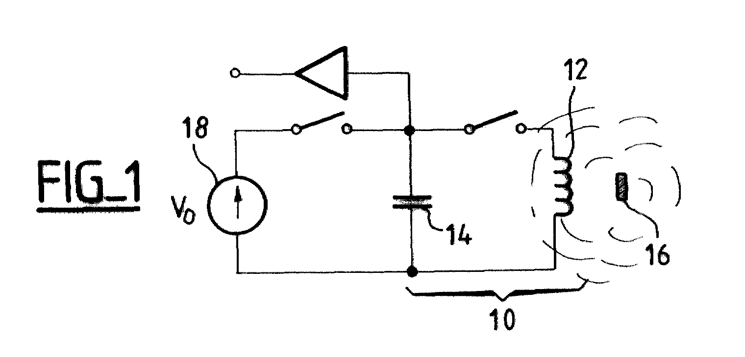
- FIG. 1 represents the resonant LC circuit with its excitation means.
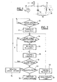
- FIG. 2 is an example of a flowchart showing the various steps for implementing the invention, in the case of a pacemaker.
- Figure 1 schematically shows the LC 10 resonant circuit, comprising a coil 12 associated (in series or in parallel) with a capacitor 14.
- the impedance of this coil 12 will be modified, in the direction of lowering the inductance, by the presence of a permanent magnet 16 near the implant.
- This decrease in inductance will, correspondingly, increase the resonance frequency of the LC circuit 10, a modification which can be detected by an appropriate circuit, for example by evaluating the response following the discharge of the capacitor 14 in the inductor 12 previously charged under a voltage V o from a generator 18. For example, one can evaluate the delay for the zero crossing of the first half-wave or of the first half-wave, as taught by the aforementioned US-A-4,611,127. which can be referred to for more details on this technique for detecting the presence of a magnet near an implant.
- the determination of the presence of a magnet was carried out by sampling, once per cardiac cycle (in the case where the implant is a device such as a pacemaker, defibrillator, cardiovertor or multisite device).
- the invention proposes to replace this measurement by sampling by a burst of measurements during the same cardiac cycle.
- N 64
- the known method for determining the presence or absence of the magnet is applied, or more precisely the presence or absence of a magnetic field of sufficient intensity to modify substantially. the inductance value of the coil 12.
- the magnet is declared present if, among the N samples, M measurements reveal the presence of an intense magnetic field.
- M with respect to N is a compromise between specificity and sensitivity of the detection of the magnet. It is preferable to choose a value M ⁇ N / 2 .
- M the detection will be more specific, but less sensitive. For example, in the presence of both an electrosurgical unit and a magnet, if M is too high, the weak magnetic component of the magnet may not be detected, the interference being sufficient to give a negative result , and this although it is desirable to operate the implant in magnet mode when using an electrosurgical unit.
- the salvo is only implemented if the first measurement is positive, which allows most of the time to preserve the consumption of the system.
- the salvo is a confirmation salvo, the most frequent mode being a scan with an isolated measurement, unique per cardiac cycle.
- the burst will be issued to determine the presence effective, or not, of a magnet according to the technique described above.
- this salvo confirms the effective presence of a magnet
- bursts in which we vary pseudo-randomly the interval between two pulses of the same burst and / or the burst recurrence period.
- Figure 2 illustrates the detailed sequence of operations that are implemented work, advantageously in wired logic by means of a microcontroller.
- this technique can be implemented by software, but at the expense of the consumption of the implant and therefore the duration of life of it.
- step 20 the process is triggered, with a frequency of the order of the second, that is to say the duration of a cardiac cycle at rest.
- step 22 After initialization of the counters (step 22), the salvo is emitted and each time burst burst we perform (step 24) the presence test of the magnet, that is to say, more precisely, the determination of a field of intensity sufficient to measurably lower the inductance of the coil. If so, a first counter is incremented (step 26) the number of positive measures.
- a burst pulse counter is incremented (step 28) and, if the number of pulses N provided in the burst is not reached (step 30), steps 24 to 28 are repeated previously. described.
- step 32 it is determined (step 32) whether or not the number of positive measurements reaches a predetermined threshold M.
- step 34 the magnet detection is invalidated and the process waits for the next trigger time salvo (step 20).
- step 36 the detection of the magnet is confirmed (step 36) and, after a delay of the order of one second (step 38), the counters are reset to zero (step 40) and the process repeats the presence test of the magnet (steps 24 and following).
- the device remains by default in the polling mode with confirmation burst.
Landscapes
- Life Sciences & Earth Sciences (AREA)
- Engineering & Computer Science (AREA)
- Physics & Mathematics (AREA)
- Remote Sensing (AREA)
- Geology (AREA)
- Environmental & Geological Engineering (AREA)
- Electromagnetism (AREA)
- General Life Sciences & Earth Sciences (AREA)
- General Physics & Mathematics (AREA)
- Geophysics (AREA)
- Electrotherapy Devices (AREA)
- External Artificial Organs (AREA)
- Magnetic Treatment Devices (AREA)
- Measuring Magnetic Variables (AREA)
Abstract
Ce circuit comprend : une bobine (12), apte à coopérer avec ledit aimant
(16) de manière à présenter une valeur diminuée d'inductance en présence
de cet aimant ; un circuit résonnant LC (10) incluant ladite bobine ;
des moyens (18) d'excitation impulsionnelle de ce circuit résonnant ; des
moyens d'analyse de la réponse impulsionnelle du circuit résonnant ; et
des moyens discriminateurs, aptes à évaluer la valeur d'inductance de la
bobine à partir de la réponse impulsionnelle ainsi analysée et, corrélativement,
à déterminer la présence ou l'absence de l'aimant. Les moyens
d'excitation sont des moyens aptes à délivrer au circuit résonnant une
salve de N impulsions successives, et les moyens d'analyse sont des
moyens aptes à déterminer les N réponses impulsionnelles correspondantes,
et les moyens discriminateurs sont des moyens aptes à déterminer
la présence de l'aimant si, parmi les N réponses impulsionnelles analysées,
un nombre M (M ≤ N) d'entre elles sont des réponses correspondant
à ladite valeur diminuée d'inductance.
Description
L'invention concerne les "dispositifs médicaux actifs", et notamment les "dispositifs médicaux implantables actifs", tels que définis par la Directive 90/385/CE du 20 juin 1990 du Conseil des communautés européennes.The invention relates to "active medical devices", and in particular to "active implantable medical devices" as defined by the Directive 90/385 / EC of 20 June 1990 of the Council of the European Communities.
Cette définition inclut les stimulateurs cardiaques, défibrillateurs, cardioverteurs et/ou dispositifs multisite, mais aussi les appareils neurologiques, les pompes de diffusion de substances médicales, les implants cochléaires, les capteurs biologiques implantés, etc., ainsi que les dispositifs de mesure de pH ou encore d'impédance intracorporelle (telle que mesure d'impédance transpulmonaire ou d'impédance intracardiaque).This definition includes pacemakers, defibrillators, cardioverters and / or multisite devices, but also neurological devices, diffusion pumps for medical substances, cochlear implants, implanted biological sensors, etc., as well as pH measurement or intracorporeal impedance (such as transpulmonary impedance or intracardiac impedance).
L'invention peut s'appliquer également de manière avantageuse à des dispositifs médicaux actifs non implantés tels que les enregistreurs Holter, qui sont des enregistreurs autonomes devant être portés par le patient pendant une longue période pour permettre le suivi en continu des signaux électrocardiographiques.The invention can also be applied advantageously to active non-implanted medical devices such as Holter recorders, which are stand-alone recorders to be carried by the patient for a long time to allow continuous tracking of signals electrocardiographic.
Nombre de ces appareils sont conçus pour être sensibles au placement d'un aimant permanent en regard du dispositif à proximité de celui-ci, notamment pour placer le dispositif dans une configuration prédéterminée à des fins de test ou pour permettre sa programmation (par télémétrie dans le cas d'un implant). Ce mode particulier, souvent appelé "mode à l'aimant" est un mode temporaire, car beaucoup de fonctions du dispositif sont inhibées dans ce mode, de sorte que le dispositif ne présente pas un fonctionnement optimum pendant cette phase.Many of these devices are designed to be sensitive to placement a permanent magnet facing the device near it, in particular to place the device in a predetermined configuration at for testing purposes or to allow programming (by telemetry in the case of an implant). This particular mode, often called "magnet mode" is a temporary mode because many of the device's functions are disabled in this mode, so the device does not have a optimum operation during this phase.
Il est essentiel de détecter la présence de l'aimant de façon fiable (c'est-à-dire avec la meilleure réjection possible des phénomènes perturbateurs), tout en évitant de grever la consommation énergétique, facteur essentiel en matière d'implants médicaux autonomes dont la durée de vie doit être la plus longue possible.It is essential to detect the presence of the magnet reliably (i.e. with the best possible rejection of disturbing phenomena), while avoiding burdening energy consumption, an essential factor in terms of autonomous medical implants whose lifespan should be as long as possible.
Une première technique de détection de l'aimant consiste à utiliser un interrupteur à lame souple (ILS) qui vient commuter un circuit au sein du dispositif.A first magnet detection technique consists in using a switch with a flexible blade (ILS) which switches a circuit within the device.
Une autre technique, à laquelle se réfère l'invention, est enseignée par le US-A-4 611 127, qui met en oeuvre un circuit oscillant LC dont la valeur d'inductance de la bobine diminue en présence d'un champ magnétique. Ce circuit résonnant est excité par un signal impulsionnel et un circuit mesure la fréquence propre d'oscillation résultante du circuit LC. En présence d'un aimant, une moindre valeur de l'inductance augmente cette fréquence de sorte que, en mesurant par exemple le délai de passage à zéro de la première alternance ou demi-alternance, on peut en déduire un abaissement de la valeur de l'inductance et par voie de conséquence la présence d'un aimant à proximité de la bobine.Another technique, to which the invention refers, is taught by the US-A-4,611,127, which implements an LC oscillating circuit whose value inductance of the coil decreases in the presence of a magnetic field. This resonant circuit is excited by a pulse signal and a measurement circuit the natural oscillation frequency resulting from the LC circuit. In the presence of a magnet, a lower value of the inductance increases this frequency so that by measuring for example the time to switch to zero of the first half-wave or half-wave, we can deduce one lowering of the value of the inductance and consequently the presence of a magnet near the coil.
L'inconvénient de cette technique est sa sensibilité aux parasites magnétiques ou électriques. En effet, des champs de forte intensité tels que ceux qui sont produits par exemple par les portiques antivol ou les fours à induction sont capables de produire une composante magnétique importante qui peut leurrer le circuit détecteur, car cette composante magnétique parasite a typiquement les mêmes effets sur la bobine et son circuit associé que le champ quasi-continu produit par un aimant.The disadvantage of this technique is its sensitivity to magnetic noise or electric. Indeed, high intensity fields such as those produced, for example, by anti-theft gantry cranes or induction are capable of producing a large magnetic component which can deceive the detector circuit, because this magnetic component parasite typically has the same effects on the coil and its circuit associated that the quasi-continuous field produced by a magnet.
Le problème est aggravé par le principe de mesure par échantillonnage, qui est adopté pour des raisons d'économie d'énergie propres aux implants actifs. Ainsi, dans le cas d'un appareil tel qu'un stimulateur cardiaque, la détermination de la présence d'un aimant est effectuée une fois par cycle cardiaque, avec le risque que l'implant, leurré par le champ magnétique alternatif parasite d'intensité suffisante pour faire varier la valeur de l'inductance, passe dans le mode à l'aimant de façon inappropriée et nocive pour la santé du porteur de l'appareil.The problem is compounded by the principle of measurement by sampling, which is adopted for reasons of energy saving specific to implants assets. So in the case of a device like a pacemaker, the determination of the presence of a magnet is carried out once by cardiac cycle, with the risk that the implant, deceived by the magnetic field parasitic alternative of sufficient intensity to vary the value of the inductance, goes into magnet mode inappropriately and harmful to the health of the wearer of the device.
Un champ électrique de forte valeur peut également induire des parasites se superposant à la réponse impulsionnelle du circuit oscillant et, de la même façon, leurrer les moyens de discrimination du passage par zéro de cette réponse.A high value electric field can also induce noise superimposed on the impulse response of the oscillating circuit and, of the same way, deceive the means of discrimination of the zero crossing of this answer.
L'un des buts de l'invention est de proposer un circuit de détection de la présence d'un aimant qui élimine, ou tout au moins réduise dans des proportions très importantes, les inconvénients précités.One of the aims of the invention is to propose a circuit for detecting the presence of a magnet which eliminates, or at least reduces in proportions very important, the aforementioned drawbacks.
Le circuit de l'invention est du type général connu d'après le US-A-4 611 127 précité, c'est-à-dire comprenant : une bobine, apte à coopérer avec ledit aimant de manière à présenter une valeur diminuée d'inductance en présence de cet aimant ; un circuit résonnant LC incluant ladite bobine ; des moyens d'excitation impulsionnelle de ce circuit résonnant ; des moyens d'analyse de la réponse impulsionnelle du circuit résonnant ; et des moyens discriminateurs, aptes à évaluer la valeur d'inductance de la bobine à partir de la réponse impulsionnelle ainsi analysée et, corrélativement, à déterminer la présence ou l'absence de l'aimant.The circuit of the invention is of the general type known from US-A-4,611 127 above, that is to say comprising: a coil, capable of cooperating with said magnet so as to have a reduced value of inductance in presence of this magnet; an LC resonant circuit including said coil; means for pulse excitation of this resonant circuit; of means for analyzing the impulse response of the resonant circuit; and discriminating means, able to assess the inductance value of the coil from the impulse response thus analyzed and, correlatively, to determine the presence or absence of the magnet.
Selon l'invention, les moyens d'excitation sont des moyens aptes à délivrer au circuit résonnant une salve de N impulsions successives, et les moyens d'analyse sont des moyens aptes à déterminer les N réponses impulsionnelles correspondantes, et les moyens discriminateurs sont des moyens aptes à déterminer la présence de l'aimant si, parmi les N réponses impulsionnelles analysées, un nombre M (M ≤ N, avec de préférence M ≥ N/2) d'entre elles sont des réponses correspondant à ladite valeur diminuée d'inductance.According to the invention, the excitation means are means capable of delivering to the resonant circuit a burst of N successive pulses, and the analysis means are means capable of determining the N corresponding impulse responses, and the discriminator means are means capable of determining the presence of the magnet if, among the N impulse responses analyzed, a number M ( M ≤ N , preferably M ≥ N / 2 ) of them are responses corresponding to said value reduced by inductance.
Très avantageusement, les moyens d'excitation sont des moyens aptes, après avoir délivré une première impulsion, à ne délivrer ensuite les N-1 impulsions suivantes de la salve que si les moyens d'analyse ont préalablement détecté, pour cette première impulsion, une réponse impulsionnelle correspondant à une valeur diminuée d'inductance.Very advantageously, the excitation means are suitable means, after having delivered a first impulse, not to then deliver the N-1 subsequent burst bursts only if the means of analysis have previously detected, for this first pulse, an impulse response corresponding to a reduced value of inductance.
Les moyens d'excitation peuvent comprendre des moyens pour faire varier de manière pseudo-aléatoire l'instant de délivrance de la première impulsion de la salve et/ou les intervalles entre les instants de délivrance des impulsions successives de la salve.The excitation means may include means for varying pseudo-randomly the moment of delivery of the first burst pulse and / or intervals between delivery times successive burst pulses.
Lorsque le dispositif médical implantable actif est un stimulateur cardiaque, défibrillateur, cardioverteur et/ou dispositif multisite, les impulsions successives de la salve sont de préférence délivrées sur une durée inférieure à la durée d'un cycle cardiaque mesuré ou stimulé par le dispositif.When the active implantable medical device is a pacemaker, defibrillator, cardioverter and / or multisite device, pulses of the burst are preferably delivered over a shorter period the duration of a cardiac cycle measured or stimulated by the device.
On va maintenant décrire un exemple de mise en oeuvre de l'invention, en référence aux dessins annexés.We will now describe an example of implementation of the invention, with reference to the accompanying drawings.
La figure 1 représente le circuit LC résonnant avec ses moyens d'excitation.FIG. 1 represents the resonant LC circuit with its excitation means.
La figure 2 est un exemple d'organigramme indiquant les diverses étapes de mise en oeuvre de l'invention, dans le cas d'un stimulateur cardiaque.Figure 2 is an example of a flowchart showing the various steps for implementing the invention, in the case of a pacemaker.
La figure 1 présente schématiquement le circuit résonnant LC 10, comprenant
une bobine 12 associée (en série ou en parallèle) à un condensateur
14.Figure 1 schematically shows the
L'impédance de ce la bobine 12 va se trouver modifiée, dans le sens de
l'abaissement de l'inductance, par la présence d'un aimant permanent 16
à proximité de l'implant. Cette diminution d'inductance va, corrélativement,
augmenter la fréquence de résonance du circuit LC 10, modification qui
pourra être détectée par un circuit approprié, par exemple en évaluant la
réponse consécutive à la décharge du condensateur 14 dans l'inductance
12 préalablement chargé sous une tension Vo issue d'un générateur 18.
Par exemple, on peut évaluer le délai pour le passage à zéro de la première
demi-alternance ou de la première alternance, comme cela est enseigné
par le US-A-4 611 127 précité auquel on pourra se référer pour
plus de détails sur cette technique de détection de la présence d'un aimant
à proximité d'un implant.The impedance of this
Jusqu'à présent, la détermination de la présence d'un aimant était effectuée par échantillonnage, une fois par cycle cardiaque (dans le cas où l'implant est un dispositif tel qu'un stimulateur cardiaque, défibrillateur, cardioverteur ou dispositif multisite).Until now, the determination of the presence of a magnet was carried out by sampling, once per cardiac cycle (in the case where the implant is a device such as a pacemaker, defibrillator, cardiovertor or multisite device).
L'invention propose de remplacer cette mesure par échantillonnage par une salve de mesures au cours d'un même cycle cardiaque.The invention proposes to replace this measurement by sampling by a burst of measurements during the same cardiac cycle.
On opère ainsi une série de N mesures (typiquement N = 64) à intervalles
de 200 µs. Pour chacune de ces mesures on applique le procédé connu
de détermination de la présence ou de l'absence de l'aimant, ou plus précisément
de la présence ou de l'absence d'un champ magnétique d'intensité
suffisante pour modifier de manière substantielle la valeur d'inductance
de la bobine 12.We thus operate a series of N measurements (typically N = 64) at 200 µs intervals. For each of these measurements, the known method for determining the presence or absence of the magnet is applied, or more precisely the presence or absence of a magnetic field of sufficient intensity to modify substantially. the inductance value of the
Une fois ces mesures effectuées, l'aimant est déclaré présent si, parmi les N échantillons, M mesures révèlent la présence d'un champ magnétique intense.Once these measurements have been made, the magnet is declared present if, among the N samples, M measurements reveal the presence of an intense magnetic field.
Le choix de M par rapport à N est un compromis entre spécificité et sensibilité de la détection de l'aimant. On choisit de préférence une valeur M ≥ N/2.The choice of M with respect to N is a compromise between specificity and sensitivity of the detection of the magnet. It is preferable to choose a value M ≥ N / 2 .
On notera que si la valeur de M est élevée, proche de N, la détection sera plus spécifique, mais moins sensible. Par exemple, en présence à la fois d'un bistouri électrique et d'un aimant, si M est trop élevé la composante magnétique, faible, de l'aimant risque de ne pas être détectée, le parasitage étant suffisant pour donner un résultat négatif, et ceci bien qu'il soit souhaitable de faire fonctionner l'implant en mode sous aimant en cas d'utilisation d'un bistouri électrique.It will be noted that if the value of M is high, close to N , the detection will be more specific, but less sensitive. For example, in the presence of both an electrosurgical unit and a magnet, if M is too high, the weak magnetic component of the magnet may not be detected, the interference being sufficient to give a negative result , and this although it is desirable to operate the implant in magnet mode when using an electrosurgical unit.
Très avantageusement, la salve n'est mise en oeuvre que si la première mesure est positive, ce qui permet dans la majeure partie du temps de préserver la consommation du système. En d'autres termes, la salve est une salve de confirmation, le mode le plus fréquent étant un mode de scrutation avec une mesure isolée, unique par cycle cardiaque.Very advantageously, the salvo is only implemented if the first measurement is positive, which allows most of the time to preserve the consumption of the system. In other words, the salvo is a confirmation salvo, the most frequent mode being a scan with an isolated measurement, unique per cardiac cycle.
Si la première mesure indique la présence d'un champ magnétique d'intensité suffisante, alors la salve sera émise pour déterminer la présence effective, ou non, d'un aimant selon la technique décrite plus haut.If the first measurement indicates the presence of a magnetic field of intensity sufficient, then the burst will be issued to determine the presence effective, or not, of a magnet according to the technique described above.
De préférence, si cette salve confirme la présence effective d'un aimant, alors on émettra systématiquement une salve complète pour tous les cycles cardiaques qui suivent jusqu'à ce que le test échoue pour la première fois, auquel cas on reprendra le mode de scrutation par mesure isolée puis salve de confirmation éventuelle. En d'autres termes, tant que l'aimant sera détecté comme présent on enverra systématiquement une salve complète, indépendamment du résultat de la première mesure de la salve, et on ne repassera en mode de scrutation qu'après retrait de l'aimant.Preferably, if this salvo confirms the effective presence of a magnet, then we will systematically issue a full burst for all cycles following until the test fails for the first time times, in which case we will resume the polling mode by isolated measurement then a possible confirmation salvo. In other words, as long as the magnet will be detected as present we will systematically send a salvo complete, regardless of the result of the first measurement of the Salvo, and we will not return to polling mode until the magnet has been removed.
Pour se protéger des parasites qui pourraient être en synchronisation ou en battement répétitif avec la fréquence des mesures dans la salve, on peut avantageusement produire des salves dans lesquelles on fait varier de manière pseudo-aléatoire l'intervalle entre deux impulsions d'une même salve et/ou la période de récurrence des salves.To protect itself from parasites which could be in synchronization or in repetitive beat with the frequency of the measurements in the burst, we can advantageously produce bursts in which we vary pseudo-randomly the interval between two pulses of the same burst and / or the burst recurrence period.
La figure 2 illustre la séquence détaillée des opérations qui sont mises en oeuvre, avantageusement en logique câblée au moyen d'un microcontrôleur. En variante, cette technique peut être mise en oeuvre par logiciel, mais au détriment de la consommation de l'implant et donc de la durée de vie de celui-ci.Figure 2 illustrates the detailed sequence of operations that are implemented work, advantageously in wired logic by means of a microcontroller. As a variant, this technique can be implemented by software, but at the expense of the consumption of the implant and therefore the duration of life of it.
À l'étape 20, le processus est déclenché, avec une périodicité de l'ordre
de la seconde, c'est-à-dire de la durée d'un cycle cardiaque au repos.In
Après initialisation des compteurs (étape 22), la salve est émise et à chaque impulsion de la salve on effectue (étape 24) le test de présence de l'aimant, c'est-à-dire, plus précisément, la détermination d'un champ d'intensité suffisante pour abaisser de manière mesurable l'inductance de la bobine. Dans l'affirmative, on incrémente (étape 26) un premier compteur du nombre de mesures positives.After initialization of the counters (step 22), the salvo is emitted and each time burst burst we perform (step 24) the presence test of the magnet, that is to say, more precisely, the determination of a field of intensity sufficient to measurably lower the inductance of the coil. If so, a first counter is incremented (step 26) the number of positive measures.
Dans tous les cas, on incrémente un compteur d'impulsions de la salve
(étape 28) et, si le nombre d'impulsions N prévues dans la salve n'est pas
atteint (étape 30), on réitère les étapes 24 à 28 précédemment décrites.In all cases, a burst pulse counter is incremented (step 28) and, if the number of pulses N provided in the burst is not reached (step 30),
En fin de salve, on détermine (étape 32) si le nombre de mesures positives atteint ou non un seuil M prédéterminé.At the end of the burst, it is determined (step 32) whether or not the number of positive measurements reaches a predetermined threshold M.
Dans la négative (étape 34) la détection de l'aimant est infirmée et le processus se met en attente de l'instant de déclenchement de la prochaine salve (étape 20).If not (step 34) the magnet detection is invalidated and the process waits for the next trigger time salvo (step 20).
Dans l'affirmative, la détection de l'aimant est confirmée (étape 36) et,
après une temporisation de l'ordre de la seconde (étape 38), les compteurs
sont remis à zéro (étape 40) et le processus réitère le test de présence
de l'aimant (étapes 24 et suivantes). Le dispositif reste par défaut
dans le mode de scrutation avec salve de confirmation.If so, the detection of the magnet is confirmed (step 36) and,
after a delay of the order of one second (step 38), the counters
are reset to zero (step 40) and the process repeats the presence test
of the magnet (
Claims (6)
Applications Claiming Priority (2)
| Application Number | Priority Date | Filing Date | Title |
|---|---|---|---|
| FR0003744A FR2806808B1 (en) | 2000-03-24 | 2000-03-24 | CIRCUIT FOR DETECTING THE PRESENCE OF A PERMANENT MAGNET IN THE VICINITY OF AN ACTIVE MEDICAL DEVICE, IN PARTICULAR A CARDIAC PACEMAKER, DEFIBRILLATOR, CARDIOVERTER AND/OR MULTI-SITE DEVICE |
| FR0003744 | 2000-03-24 |
Publications (2)
| Publication Number | Publication Date |
|---|---|
| EP1136845A1 true EP1136845A1 (en) | 2001-09-26 |
| EP1136845B1 EP1136845B1 (en) | 2008-10-15 |
Family
ID=8848445
Family Applications (1)
| Application Number | Title | Priority Date | Filing Date |
|---|---|---|---|
| EP01400738A Expired - Lifetime EP1136845B1 (en) | 2000-03-24 | 2001-03-22 | Circuit for detecting the presence of a permanent magnet near to an active medical device |
Country Status (6)
| Country | Link |
|---|---|
| US (1) | US6487452B2 (en) |
| EP (1) | EP1136845B1 (en) |
| JP (1) | JP4365048B2 (en) |
| AT (1) | ATE411539T1 (en) |
| DE (1) | DE60136120D1 (en) |
| FR (1) | FR2806808B1 (en) |
Families Citing this family (16)
| Publication number | Priority date | Publication date | Assignee | Title |
|---|---|---|---|---|
| US6650111B2 (en) * | 2001-07-18 | 2003-11-18 | Eaton Corporation | Pulsed excited proximity sensor |
| ITMO20030300A1 (en) * | 2003-11-07 | 2005-05-08 | M D Micro Detectors Spa | INDUCTIVE PROXIMITY SENSOR, IN PARTICULAR TO DETECT THE PRESENCE OF FERROUS AND NON-FERROUS MATERIALS |
| PT1580889E (en) * | 2004-03-26 | 2008-03-17 | Senstronic S A | Inductive proximity sensor |
| US7794499B2 (en) | 2004-06-08 | 2010-09-14 | Theken Disc, L.L.C. | Prosthetic intervertebral spinal disc with integral microprocessor |
| US8014867B2 (en) | 2004-12-17 | 2011-09-06 | Cardiac Pacemakers, Inc. | MRI operation modes for implantable medical devices |
| US7561915B1 (en) | 2004-12-17 | 2009-07-14 | Cardiac Pacemakers, Inc. | MRI system having implantable device safety features |
| US8214797B2 (en) * | 2007-02-01 | 2012-07-03 | Microsoft Corporation | Visual association creation for object relational class development |
| US9599448B2 (en) * | 2007-11-29 | 2017-03-21 | Rockwell Automation Technologies, Inc. | Apparatus and methods for proximity sensing circuitry |
| US8032228B2 (en) | 2007-12-06 | 2011-10-04 | Cardiac Pacemakers, Inc. | Method and apparatus for disconnecting the tip electrode during MRI |
| US8086321B2 (en) | 2007-12-06 | 2011-12-27 | Cardiac Pacemakers, Inc. | Selectively connecting the tip electrode during therapy for MRI shielding |
| US8311637B2 (en) | 2008-02-11 | 2012-11-13 | Cardiac Pacemakers, Inc. | Magnetic core flux canceling of ferrites in MRI |
| US8160717B2 (en) | 2008-02-19 | 2012-04-17 | Cardiac Pacemakers, Inc. | Model reference identification and cancellation of magnetically-induced voltages in a gradient magnetic field |
| US8571661B2 (en) | 2008-10-02 | 2013-10-29 | Cardiac Pacemakers, Inc. | Implantable medical device responsive to MRI induced capture threshold changes |
| US8639331B2 (en) | 2009-02-19 | 2014-01-28 | Cardiac Pacemakers, Inc. | Systems and methods for providing arrhythmia therapy in MRI environments |
| AU2010328622B2 (en) | 2009-12-08 | 2014-09-11 | Cardiac Pacemakers, Inc. | Implantable medical device with automatic tachycardia detection and control in MRI environments |
| US9649165B2 (en) * | 2012-07-16 | 2017-05-16 | Cardiac Innovation, Llc | Medical device identifier |
Citations (3)
| Publication number | Priority date | Publication date | Assignee | Title |
|---|---|---|---|---|
| US4611127A (en) * | 1984-09-20 | 1986-09-09 | Telectronics N.V. | Electronic sensor for static magnetic field |
| US4821023A (en) * | 1988-01-07 | 1989-04-11 | Del Norte Technology, Inc. | Walk-through metal detector |
| US6018296A (en) * | 1997-07-09 | 2000-01-25 | Vacuumschmelze Gmbh | Amorphous magnetostrictive alloy with low cobalt content and method for annealing same |
Family Cites Families (7)
| Publication number | Priority date | Publication date | Assignee | Title |
|---|---|---|---|---|
| US4260949A (en) * | 1978-06-12 | 1981-04-07 | Dalton Murphy L Jun | Magnetic field detection apparatus |
| US4541431A (en) * | 1984-09-20 | 1985-09-17 | Telectronics Pty. Ltd. | Use of telemetry coil to replace magnetically activated reed switch in implantable devices |
| EP0590179B1 (en) * | 1992-09-29 | 1997-01-15 | Pacesetter AB | Magnet position detector |
| SE9400622D0 (en) * | 1994-02-23 | 1994-02-23 | Siemens Elema Ab | Medical implant |
| SE9403188D0 (en) * | 1994-09-22 | 1994-09-22 | Siemens Elema Ab | Magnetic field detector on a medical implant |
| SE9404374D0 (en) * | 1994-12-15 | 1994-12-15 | Pacesetter Ab | magnetic field detector |
| US6082367A (en) * | 1998-04-29 | 2000-07-04 | Medtronic, Inc. | Audible sound communication from an implantable medical device |
-
2000
- 2000-03-24 FR FR0003744A patent/FR2806808B1/en not_active Expired - Fee Related
-
2001
- 2001-03-22 AT AT01400738T patent/ATE411539T1/en not_active IP Right Cessation
- 2001-03-22 EP EP01400738A patent/EP1136845B1/en not_active Expired - Lifetime
- 2001-03-22 DE DE60136120T patent/DE60136120D1/en not_active Expired - Lifetime
- 2001-03-23 JP JP2001084226A patent/JP4365048B2/en not_active Expired - Lifetime
- 2001-03-23 US US09/816,646 patent/US6487452B2/en not_active Expired - Lifetime
Patent Citations (3)
| Publication number | Priority date | Publication date | Assignee | Title |
|---|---|---|---|---|
| US4611127A (en) * | 1984-09-20 | 1986-09-09 | Telectronics N.V. | Electronic sensor for static magnetic field |
| US4821023A (en) * | 1988-01-07 | 1989-04-11 | Del Norte Technology, Inc. | Walk-through metal detector |
| US6018296A (en) * | 1997-07-09 | 2000-01-25 | Vacuumschmelze Gmbh | Amorphous magnetostrictive alloy with low cobalt content and method for annealing same |
Also Published As
| Publication number | Publication date |
|---|---|
| JP2002000740A (en) | 2002-01-08 |
| DE60136120D1 (en) | 2008-11-27 |
| US6487452B2 (en) | 2002-11-26 |
| US20010032650A1 (en) | 2001-10-25 |
| EP1136845B1 (en) | 2008-10-15 |
| ATE411539T1 (en) | 2008-10-15 |
| JP4365048B2 (en) | 2009-11-18 |
| FR2806808A1 (en) | 2001-09-28 |
| FR2806808B1 (en) | 2002-05-24 |
Similar Documents
| Publication | Publication Date | Title |
|---|---|---|
| EP1136845B1 (en) | Circuit for detecting the presence of a permanent magnet near to an active medical device | |
| EP0550343B1 (en) | Process and system for the analysis of the cardiac activity for implantable treatment device of tachycardia | |
| EP0826392B1 (en) | Apparatus for extracting an evoked response component from a sensed cardiac signal by suppressing electrode polarization components | |
| JP4668175B2 (en) | Biomedical signal processing method and apparatus using wavelets | |
| EP2206532B1 (en) | Implantable medical heart device comprising means for detecting intense static magnetic fields and commuting to safety mode during MRI tests | |
| JPH09508819A (en) | Confirmation method of heart capture by pacemaker | |
| JP2000502271A (en) | Cardiac excitation device for confirming atrial capture | |
| EP2412401B1 (en) | Active implantable medical device with means for testing ventricular capture by analysing an endocardiac acceleration signal | |
| EP0947217A2 (en) | Apparatus to remove data outliers, produced by external disturbance, in internally measured signals in an implantable cardiac stimulator | |
| EP1007150B1 (en) | Apparatus for tissue stimulation | |
| EP2347790B1 (en) | Implantable prosthetic heart including a means for detecting and protecting against the strong magnetic fields generated by MRI machines | |
| FR2986158A1 (en) | ACTIVE IMPLANTABLE MEDICAL DEVICE COMPRISING MEANS FOR DIAGNOSING HEART FAILURE | |
| EP2742971B1 (en) | Active implantable medical device such as a pacemaker with capture testing by simplified analysis of a vector cardiogram | |
| FR2816218A1 (en) | IMPLANTABLE ACTIVE MEDICAL DEVICE, IN PARTICULAR CARDIAC PACEMAKER, DEFIBRILLATOR, CARDIOVERTER OR MULTI-SITE DEVICE, COMPRISING MEANS FOR DETECTION OF A RISK OF FUSION SITUATION | |
| EP1308183B1 (en) | Active implantable medical device for treating heart rhythm disorders, having improved means for detecting atrial arrhythmias | |
| EP1161965B1 (en) | Active implantable medical device, of the type pacemaker, defibrillator, cardioverter and/or multisite device with improved detection of late atrial extrasystols | |
| FR2999440A1 (en) | ACTIVE IMPLANTABLE MEDICAL DEVICE OF CARDIAC STIMULATOR TYPE HAVING ANODIC STIMULATION DETECTION BY VECTOGRAM ANALYSIS | |
| US5601614A (en) | Method and device for determining whether electrical signals in a heart are caused by an atrial depolarization | |
| EP1091785B1 (en) | Evoked response detector for a heart stimulator | |
| EP0875264B1 (en) | Double chamber implantable pacemaker/defibrillator with AV cross-talk protection | |
| EP1731195B1 (en) | Active implantable medical device with AAI/DDD mode switching, in particular pacemaker, with improved control of mode switching in the presence of uncertain ventricular events | |
| EP2596832A1 (en) | Implantable cardioverter-defibrillator medical device with dynamically adjustable ventricular sensing threshold | |
| EP0884065A1 (en) | Device and method for determining a criterion of frequent occurance or severe extrasystoles (atrial or ventricular) | |
| EP2332462B1 (en) | Single-chamber implantable cardioverter/defibrillator with detection of atrial activity via the single-body probe | |
| EP1275414B1 (en) | Active implantable medical device for treating heart rhythm disorders, having compensation means for the voltage self-induced by the detection circuit amplifiers |
Legal Events
| Date | Code | Title | Description |
|---|---|---|---|
| PUAI | Public reference made under article 153(3) epc to a published international application that has entered the european phase |
Free format text: ORIGINAL CODE: 0009012 |
|
| AK | Designated contracting states |
Kind code of ref document: A1 Designated state(s): AT BE CH CY DE DK ES FI FR GB GR IE IT LI LU MC NL PT SE TR |
|
| AX | Request for extension of the european patent |
Free format text: AL;LT;LV;MK;RO;SI |
|
| 17P | Request for examination filed |
Effective date: 20011201 |
|
| AKX | Designation fees paid |
Free format text: AT BE CH CY DE DK ES FI FR GB GR IE IT LI LU MC NL PT SE TR |
|
| GRAP | Despatch of communication of intention to grant a patent |
Free format text: ORIGINAL CODE: EPIDOSNIGR1 |
|
| RTI1 | Title (correction) |
Free format text: CIRCUIT FOR DETECTING THE PRESENCE OF A PERMANENT MAGNET NEAR TO AN ACTIVE MEDICAL DEVICE |
|
| GRAS | Grant fee paid |
Free format text: ORIGINAL CODE: EPIDOSNIGR3 |
|
| GRAA | (expected) grant |
Free format text: ORIGINAL CODE: 0009210 |
|
| AK | Designated contracting states |
Kind code of ref document: B1 Designated state(s): AT BE CH CY DE DK ES FI FR GB GR IE IT LI LU MC NL PT SE TR |
|
| REG | Reference to a national code |
Ref country code: CH Ref legal event code: EP Ref country code: GB Ref legal event code: FG4D Free format text: NOT ENGLISH |
|
| REG | Reference to a national code |
Ref country code: IE Ref legal event code: FG4D Free format text: LANGUAGE OF EP DOCUMENT: FRENCH |
|
| REF | Corresponds to: |
Ref document number: 60136120 Country of ref document: DE Date of ref document: 20081127 Kind code of ref document: P |
|
| REG | Reference to a national code |
Ref country code: SE Ref legal event code: TRGR |
|
| NLV1 | Nl: lapsed or annulled due to failure to fulfill the requirements of art. 29p and 29m of the patents act | ||
| PG25 | Lapsed in a contracting state [announced via postgrant information from national office to epo] |
Ref country code: ES Free format text: LAPSE BECAUSE OF FAILURE TO SUBMIT A TRANSLATION OF THE DESCRIPTION OR TO PAY THE FEE WITHIN THE PRESCRIBED TIME-LIMIT Effective date: 20090126 Ref country code: AT Free format text: LAPSE BECAUSE OF FAILURE TO SUBMIT A TRANSLATION OF THE DESCRIPTION OR TO PAY THE FEE WITHIN THE PRESCRIBED TIME-LIMIT Effective date: 20081015 |
|
| PG25 | Lapsed in a contracting state [announced via postgrant information from national office to epo] |
Ref country code: FI Free format text: LAPSE BECAUSE OF FAILURE TO SUBMIT A TRANSLATION OF THE DESCRIPTION OR TO PAY THE FEE WITHIN THE PRESCRIBED TIME-LIMIT Effective date: 20081015 Ref country code: PT Free format text: LAPSE BECAUSE OF FAILURE TO SUBMIT A TRANSLATION OF THE DESCRIPTION OR TO PAY THE FEE WITHIN THE PRESCRIBED TIME-LIMIT Effective date: 20090316 Ref country code: NL Free format text: LAPSE BECAUSE OF FAILURE TO SUBMIT A TRANSLATION OF THE DESCRIPTION OR TO PAY THE FEE WITHIN THE PRESCRIBED TIME-LIMIT Effective date: 20081015 |
|
| PG25 | Lapsed in a contracting state [announced via postgrant information from national office to epo] |
Ref country code: DK Free format text: LAPSE BECAUSE OF FAILURE TO SUBMIT A TRANSLATION OF THE DESCRIPTION OR TO PAY THE FEE WITHIN THE PRESCRIBED TIME-LIMIT Effective date: 20081015 |
|
| PLBE | No opposition filed within time limit |
Free format text: ORIGINAL CODE: 0009261 |
|
| STAA | Information on the status of an ep patent application or granted ep patent |
Free format text: STATUS: NO OPPOSITION FILED WITHIN TIME LIMIT |
|
| 26N | No opposition filed |
Effective date: 20090716 |
|
| BERE | Be: lapsed |
Owner name: ELA MEDICAL Effective date: 20090331 |
|
| PG25 | Lapsed in a contracting state [announced via postgrant information from national office to epo] |
Ref country code: MC Free format text: LAPSE BECAUSE OF NON-PAYMENT OF DUE FEES Effective date: 20090331 |
|
| REG | Reference to a national code |
Ref country code: CH Ref legal event code: PL |
|
| PG25 | Lapsed in a contracting state [announced via postgrant information from national office to epo] |
Ref country code: LI Free format text: LAPSE BECAUSE OF NON-PAYMENT OF DUE FEES Effective date: 20090331 Ref country code: CH Free format text: LAPSE BECAUSE OF NON-PAYMENT OF DUE FEES Effective date: 20090331 |
|
| PG25 | Lapsed in a contracting state [announced via postgrant information from national office to epo] |
Ref country code: BE Free format text: LAPSE BECAUSE OF NON-PAYMENT OF DUE FEES Effective date: 20090331 |
|
| PG25 | Lapsed in a contracting state [announced via postgrant information from national office to epo] |
Ref country code: GR Free format text: LAPSE BECAUSE OF FAILURE TO SUBMIT A TRANSLATION OF THE DESCRIPTION OR TO PAY THE FEE WITHIN THE PRESCRIBED TIME-LIMIT Effective date: 20090116 |
|
| PG25 | Lapsed in a contracting state [announced via postgrant information from national office to epo] |
Ref country code: LU Free format text: LAPSE BECAUSE OF NON-PAYMENT OF DUE FEES Effective date: 20090322 |
|
| PG25 | Lapsed in a contracting state [announced via postgrant information from national office to epo] |
Ref country code: TR Free format text: LAPSE BECAUSE OF FAILURE TO SUBMIT A TRANSLATION OF THE DESCRIPTION OR TO PAY THE FEE WITHIN THE PRESCRIBED TIME-LIMIT Effective date: 20081015 |
|
| PG25 | Lapsed in a contracting state [announced via postgrant information from national office to epo] |
Ref country code: CY Free format text: LAPSE BECAUSE OF FAILURE TO SUBMIT A TRANSLATION OF THE DESCRIPTION OR TO PAY THE FEE WITHIN THE PRESCRIBED TIME-LIMIT Effective date: 20081015 |
|
| PGFP | Annual fee paid to national office [announced via postgrant information from national office to epo] |
Ref country code: SE Payment date: 20130312 Year of fee payment: 13 Ref country code: IE Payment date: 20130312 Year of fee payment: 13 |
|
| REG | Reference to a national code |
Ref country code: SE Ref legal event code: EUG |
|
| PG25 | Lapsed in a contracting state [announced via postgrant information from national office to epo] |
Ref country code: SE Free format text: LAPSE BECAUSE OF NON-PAYMENT OF DUE FEES Effective date: 20140323 |
|
| REG | Reference to a national code |
Ref country code: IE Ref legal event code: MM4A |
|
| PG25 | Lapsed in a contracting state [announced via postgrant information from national office to epo] |
Ref country code: IE Free format text: LAPSE BECAUSE OF NON-PAYMENT OF DUE FEES Effective date: 20140322 |
|
| REG | Reference to a national code |
Ref country code: FR Ref legal event code: PLFP Year of fee payment: 16 |
|
| REG | Reference to a national code |
Ref country code: FR Ref legal event code: PLFP Year of fee payment: 17 |
|
| REG | Reference to a national code |
Ref country code: FR Ref legal event code: PLFP Year of fee payment: 18 |
|
| PGFP | Annual fee paid to national office [announced via postgrant information from national office to epo] |
Ref country code: DE Payment date: 20180306 Year of fee payment: 18 Ref country code: GB Payment date: 20180321 Year of fee payment: 18 |
|
| PGFP | Annual fee paid to national office [announced via postgrant information from national office to epo] |
Ref country code: IT Payment date: 20180321 Year of fee payment: 18 Ref country code: FR Payment date: 20180223 Year of fee payment: 18 |
|
| REG | Reference to a national code |
Ref country code: DE Ref legal event code: R119 Ref document number: 60136120 Country of ref document: DE |
|
| GBPC | Gb: european patent ceased through non-payment of renewal fee |
Effective date: 20190322 |
|
| PG25 | Lapsed in a contracting state [announced via postgrant information from national office to epo] |
Ref country code: GB Free format text: LAPSE BECAUSE OF NON-PAYMENT OF DUE FEES Effective date: 20190322 Ref country code: DE Free format text: LAPSE BECAUSE OF NON-PAYMENT OF DUE FEES Effective date: 20191001 |
|
| PG25 | Lapsed in a contracting state [announced via postgrant information from national office to epo] |
Ref country code: IT Free format text: LAPSE BECAUSE OF NON-PAYMENT OF DUE FEES Effective date: 20190322 Ref country code: FR Free format text: LAPSE BECAUSE OF NON-PAYMENT OF DUE FEES Effective date: 20190331 |
|
| P01 | Opt-out of the competence of the unified patent court (upc) registered |
Effective date: 20230714 |