EP1136629B1 - Sanitary fitting for flushing - Google Patents
Sanitary fitting for flushing Download PDFInfo
- Publication number
- EP1136629B1 EP1136629B1 EP01810215A EP01810215A EP1136629B1 EP 1136629 B1 EP1136629 B1 EP 1136629B1 EP 01810215 A EP01810215 A EP 01810215A EP 01810215 A EP01810215 A EP 01810215A EP 1136629 B1 EP1136629 B1 EP 1136629B1
- Authority
- EP
- European Patent Office
- Prior art keywords
- fitting
- coupling element
- fitting body
- water pipe
- building wall
- Prior art date
- Legal status (The legal status is an assumption and is not a legal conclusion. Google has not performed a legal analysis and makes no representation as to the accuracy of the status listed.)
- Expired - Lifetime
Links
Images
Classifications
-
- E—FIXED CONSTRUCTIONS
- E03—WATER SUPPLY; SEWERAGE
- E03C—DOMESTIC PLUMBING INSTALLATIONS FOR FRESH WATER OR WASTE WATER; SINKS
- E03C1/00—Domestic plumbing installations for fresh water or waste water; Sinks
- E03C1/02—Plumbing installations for fresh water
- E03C1/04—Water-basin installations specially adapted to wash-basins or baths
- E03C1/042—Arrangements on taps for wash-basins or baths for connecting to the wall
-
- E—FIXED CONSTRUCTIONS
- E03—WATER SUPPLY; SEWERAGE
- E03D—WATER-CLOSETS OR URINALS WITH FLUSHING DEVICES; FLUSHING VALVES THEREFOR
- E03D3/00—Flushing devices operated by pressure of the water supply system flushing valves not connected to the water-supply main, also if air is blown in the water seal for a quick flushing
Definitions
- the invention relates to a sanitary flush valve with a housing in which a fitting body is arranged with a water guide channel, which channel has an input and an output and with a fastening device for fastening the fitting body to a building wall.
- Fittings of the type mentioned are known and are used in particular for the pressure flushing of urinals.
- the valve accommodated in the fitting is opened, for example, with a non-contact control.
- rinsing water flows from a water pipe through the water supply channel of the fitting body and through a rinsing pipe and finally reaches the sanitary body to be rinsed.
- mounting the flush valve must be attached to a building wall and connected to the water pipe and to the flushing line. For a long time there has been a desire to perform such assembly work with the least possible effort and yet safe.
- a flush valve has become known in which the fitting body, a threaded connector is formed, which serves as a direct fastening element on the water line.
- the threaded connection simultaneously forms the water connection and has an internal passage to the channel of the fitting body.
- the invention has for its object to provide a sanitary flush valve of the type mentioned, which is universal fastened without much higher cost.
- the object is achieved in a generic sanitary flush valve characterized in that the fastening device has a coupling element which is connected by means of Renk fürskarn with the fitting body and having further connection means for its attachment to a building wall or to a water pipe.
- the coupling element is first attached, for example by means of dowels to a building wall or by means of a threaded connector to a water pipe. Subsequently, the fitting is attached by means of bayonets on the attached coupling element. Also in the case of fastening with dowels, the installation is very simple and efficient possible.
- the fitting body is the same in both types of attachment at least in the basic structure, which greatly simplifies the production. Also possible is an embodiment in which the fitting body is the same for both types of fastening. Different is then only the coupling element.
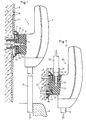
- the sanitary flush valve 1 shown in Figure 1 is an input side to a water line 12 shown here only partially connected and the output side to a purge line 13.
- the purge line 13 leads to a sanitary appliance 14, which is merely indicated here and in particular is a urinal.
- the water pipe 12 is at its front approximately flush with the wall surface 11 of a building wall 9, which may be covered with tiles 10, for example.
- the sanitary flush valve 1 has a housing 2, which is made for example of plastic and which may be multi-part.
- a not shown here valve is arranged, which can be opened with a triggering device, also not shown for flushing.
- the triggering device is, for example, a non-contact device.
- the flushing can thus be triggered by an approach of a person become.
- Such devices are well known to those skilled in the art and therefore need not be explained here.
- the flush valve can also be provided with a different operation. After flushing the valve closes automatically again and thus closes a channel 6, which leads to the passage of rinse water from the water pipe 12 to the purge line 13.
- the channel 6 passes through a fitting body 5, which is housed in a tubular extension 3 of the housing 2.
- a plurality of bayonets 19 are formed, which form a recessed connection with bayonets 32 of a coupling element 8.
- the coupling element 8 is integrally formed and has a threaded connector 18 which has an external thread 18a.
- the threaded connector 18 is screwed into the water pipe 12, which has a corresponding internal thread 12a.
- An opening 4 of the neck 3 is covered by a sleeve 7. As FIG. 1 shows, the sleeve 7 is displaceable on the projection 3 to compensate for different wall distances.
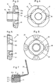
- the coupling element 8 is shown in FIGS. 3 and 4. As can be seen, the coupling element 8 has a radially outwardly directed flange 15, which has a circumferential and annular. Recess 15 a, in which four bayonets 16 are arranged. A central passage 17 forms a passage for the rinse water and is partially formed by a tubular extension 38, which receives a projection 39 of the fitting body 5 according to FIG. By means of a sealing ring 40, the two lugs 38 and 39 are sealed against each other. When joining the Renktagen thus the coupling element 8 and the fitting body 5 are sealed together. When mounting the coupling element 8 in the line 12th screwed.
- the fitting 1 is attached to the fitting body 5 on the coupling element 8 in a known manner by a rotary motion.
- the purge line 13 is secured with a union nut, not shown here
- the housing 2 is placed, which may be multi-part as mentioned above.
- the sanitary flush valve 20 according to Figure 2 differs from the valve 1 essentially by a coupling element 26 and by the connection of the water pipe 22.
- the coupling element 26 has according to Figures 5 and 6 also has a central passage 30 and a flange 31.
- the attachment however, the coupling element 26 on a building wall 9 takes place here with several, for example, four dowels 27, wherein the flange 31 according to Figure 6 has symmetrically distributed slots 29. These slots 29 allow a limited amount of rotation of the coupling element 26 for alignment of the fitting 20 with respect to the water pipe 22 and the purge line 13.
- To attach a fitting body 23 on the coupling element 26 a plurality of bayonets 41 are integrally formed on this, with corresponding bayonets 32 of the coupling element 26th give a Reenkharm.
- the coupling element 26 is fastened with the dowels 27 on the building wall 9.
- spacer rings 28 may be used. After securing the coupling element 26th the fitting body 23 is attached to this element 26. Subsequently, the water pipe 22 and the flushing pipe 13 are connected. Finally, the housing 21 is completed.
- a clamping element 34 is arranged, which is here a threaded pin, which is screwed in by means of an Allen wrench 35 until an end 34 a rests against a flange 31 and thus jammed the connection .
- the Renktagen requires no stop and thus the fitting is precisely aligned by turning in a simple manner.
Abstract
Description
Die Erfindung betrifft eine Sanitär-Spülarmatur mit einem Gehäuse, in dem ein Armaturenkörper mit einem Wasserführungskanal angeordnet ist, welcher Kanal einen Eingang und einen Ausgang aufweist und mit einer Befestigungsvorrichtung zum Befestigen des Armaturenkörpers an einer Gebäudewand.The invention relates to a sanitary flush valve with a housing in which a fitting body is arranged with a water guide channel, which channel has an input and an output and with a fastening device for fastening the fitting body to a building wall.
Armaturen der genannten Art sind bekannt und werden insbesondere für die Druckspülung von Urinalen verwendet. Zur Auslösung einer Spülung wird beispielsweise mit einer berührungslosen Steuerung das in der Armatur untergebrachte Ventil geöffnet. Bei geöffnetem Ventil strömt Spülwasser von einer Wasserleitung durch den Wasserführungskanal des Armaturenkörpers und durch eine Spülleitung und gelangt schliesslich in den zu spülenden Sanitärkörper. Beim Montieren muss die Spülarmatur an einer Gebäudewand befestigt und an die Wasserleitung sowie an die Spülleitung angeschlossen werden. Seit langem besteht das Bestreben, solche Montagearbeiten mit möglichst geringem Aufwand und dennoch sicher durchführen zu können.Fittings of the type mentioned are known and are used in particular for the pressure flushing of urinals. To initiate a flushing, the valve accommodated in the fitting is opened, for example, with a non-contact control. When the valve is open, rinsing water flows from a water pipe through the water supply channel of the fitting body and through a rinsing pipe and finally reaches the sanitary body to be rinsed. When mounting the flush valve must be attached to a building wall and connected to the water pipe and to the flushing line. For a long time there has been a desire to perform such assembly work with the least possible effort and yet safe.
Aus der DE-U-9205769 ist eine Spülarmatur bekannt geworden, bei welcher am Armaturenkörper ein Gewindestutzen angeformt ist, der als direktes Befestigungselement an der Wasserleitung dient. Beim Montieren wird die Spülarmatur mit dem Gewindestutzen auf die Mündung der Spülleitung aufgeschraubt. Der Gewindestutzen bildet gleichzeitig den Wasseranschluss und besitzt eine innere Durchleitung zum Kanal des Armaturenkörpers. Bei dieser Armatur besteht die Schwierigkeit, dass sie nur dort verwendbar ist, wo die Mündung der Wasserleitung in geeigneter Stellung zur Gebäudewand angeordnet ist. Verläuft die Wasserleitung parallel zu einer Wandfläche, so kann diese Armatur nicht wie vorgesehen befestigt werden. Es muss dann eine völlig andere Befestigungsart verwendet werden. Der Erfindung liegt die Aufgabe zugrunde, eine Sanitär-Spülarmatur der genannten Art zu schaffen, die ohne wesentlich höheren Aufwand universeller befestigbar ist.From DE-U-9205769 a flush valve has become known in which the fitting body, a threaded connector is formed, which serves as a direct fastening element on the water line. When mounting the flushing valve is screwed with the threaded connector on the mouth of the flushing line. The threaded connection simultaneously forms the water connection and has an internal passage to the channel of the fitting body. In this fitting There is the difficulty that it can only be used where the mouth of the water pipe is arranged in a suitable position to the building wall. If the water pipe runs parallel to a wall surface, then this valve can not be fixed as intended. It must then be used a completely different type of attachment. The invention has for its object to provide a sanitary flush valve of the type mentioned, which is universal fastened without much higher cost.
Die Aufgabe ist bei einer gattungsgemässen Sanitär-Spülarmatur dadurch gelöst, dass die Befestigungsvorrichtung ein Kupplungselement aufweist, das mittels Renkverbindungsmitteln mit dem Armaturenkörper verbunden ist und das weitere Verbindungsmittel zu seiner Befestigung an einer Gebäudewand oder an einer Wasserleitung aufweist.The object is achieved in a generic sanitary flush valve characterized in that the fastening device has a coupling element which is connected by means of Renkverbindungsmitteln with the fitting body and having further connection means for its attachment to a building wall or to a water pipe.
Bei der erfindungsgemässen Armatur wird zuerst das Kupplungselement beispielsweise mittels Dübeln an einer Gebäudewand oder mittels eines Gewindestutzens an einer Wasserleitung befestigt. Anschliessend wird die Armatur mittels Bajonetten am befestigten Kupplungselement befestigt. Auch im Fall einer Befestigung mit Dübeln ist die Montage sehr einfach und rationel möglich. Der Armaturkörper ist bei beiden Arten der Befestigung zumindest im Grundaufbau gleich, was die Herstellung wesentlich vereinfacht. Möglich ist auch eine Ausführung, bei der für beide Befestigungsarten der Armaturenkörper gleich ist. Unterschiedlich ist dann lediglich das Kupplungselement.In the inventive fitting, the coupling element is first attached, for example by means of dowels to a building wall or by means of a threaded connector to a water pipe. Subsequently, the fitting is attached by means of bayonets on the attached coupling element. Also in the case of fastening with dowels, the installation is very simple and efficient possible. The fitting body is the same in both types of attachment at least in the basic structure, which greatly simplifies the production. Also possible is an embodiment in which the fitting body is the same for both types of fastening. Different is then only the coupling element.
Weitere vorteilhafte Merkmale ergeben sich aus den abhängigen Patentansprüchen, der nachfolgenden Beschreibung sowie der Zeichnung.Further advantageous features emerge from the dependent claims, the following description and the drawings.
Zwei Ausführungsbeispiele der Erfindung werden nachfolgend anhand der Zeichnung näher erläutert. Es zeigen:
Figur 1- eine teilweise geschnittene erfindungsgemässe Sanitär-Spülarmatur, wobei diese an einer Wasserleitung befestigt ist,
Figur 2- eine teilweise geschnittene Sanitär-Spülarmatur, wobei diese an einer Gebäudewand befestigt ist,
- Figur 3
- ein Schnitt durch das Kupplungselement der Armatur gemäss
Figur 1, Figur 4- eine Ansicht des Kupplungselementes gemäss Figur 3,
Figur 5- ein Schnitt durch das Kupplungselement der Armatur gemäss
Figur 2, Figur 6- eine Ansicht des Kupplungselementes gemäss
Figur 5 und Figur 7- schematisch das Fixieren der Renkverbindung.
- FIG. 1
- a partially cut inventive sanitary flush valve, which is attached to a water pipe,
- FIG. 2
- a partially cut sanitary flush valve, which is attached to a building wall,
- FIG. 3
- a section through the coupling element of the fitting according to Figure 1,
- FIG. 4
- a view of the coupling element according to Figure 3,
- FIG. 5
- a section through the coupling element of the fitting according to Figure 2,
- FIG. 6
- a view of the coupling element according to Figure 5 and
- FIG. 7
- schematically fixing the Renkverbindung.
Die in Figur 1 gezeigte Sanitär-Spülarmatur 1 ist ein eingangseitig an eine hier nur abschnittsweise gezeigte Wasserleitung 12 und ausgangsseitig an eine Spülleitung 13 angeschlossen. Die Spülleitung 13 führt zu einem Sanitärapparat 14, der hier lediglich angedeutet ist und der insbesondere ein Urinal ist. Die Wasserleitung 12 ist an ihre Stirnseite etwa bündig zur Wandfläche 11 einer Gebäudewand 9, die beispielsweise mit Fliesen 10 abgedeckt sein kann.The
Die Sanitär-Spülarmatur 1 weist ein Gehäuse 2 auf, das beispielsweise aus Kunststoff hergestellt ist und das mehrteilig sein kann. Im Gehäuse 2 ist ein hier nicht gezeigtes Ventil angeordnet, welches mit einer ebenfalls nicht gezeigten Auslöseeinrichtung zur Spülauslösung geöffnet werden kann. Die Auslöseeinrichtung ist beispielsweise eine berührungslose Einrichtung. Die Spülung kann somit durch eine Annäherung einer Person ausgelöst werden. Solche Einrichtungen sind dem Fachmann gut bekannt und brauchen hier deshalb nicht erläutert zu werden. Die Spülarmatur kann aber auch mit einer anderen Betätigung versehen sein. Nach einer Spülung schliesst das Ventil selbsttätig wieder und schliesst damit einen Kanal 6, der für den Durchgang von Spülwasser von der Wasserleitung 12 bis zur Spülleitung 13 führt.The
Der Kanal 6 führt durch einen Armaturenkörper 5, der in einem rohrförmigen Ansatz 3 des Gehäuses 2 untergebracht ist. An diesem Armaturenkörper 5 sind mehrere Bajonette 19 angeformt, die mit Bajonetten 32 eines Kupplungselementes 8 eine Renkverbindung bilden.The
Das Kupplungselement 8 ist einstückig ausgebildet und weist einen Gewindestutzen 18 auf, der ein Aussengewinde 18a besitzt. Der Gewindestutzen 18 ist in die Wasserleitung 12 eingeschraubt, die ein entsprechendes Innengewinde 12a aufweist. Eine Öffnung 4 des Ansatzes 3 ist mittels einer Manchette 7 abgedeckt. Wie die Figur 1 zeigt, ist die Manchette 7 auf dem Ansatz 3 zum Ausgleich von unterschiedenen Wandabständen verschiebbar.The
Das Kupplungselement 8 ist in den Figuren 3 und 4 dargestellt. Wie ersichtlich weist das Kupplungselement 8 einen radial nach aussen gerichteten Flansch 15 auf, der eine umlaufende und ringförmige. Ausnehmung 15a aufweist, in welcher vier Bajonette 16 angeordnet sind. Ein zentraler Durchgang 17 bildet einen Durchlass für das Spülwasser und wird teilweise durch einen rohrförmigen Ansatz 38 gebildet, der gemäss Figur 1 einen Ansatz 39 des Armaturenkörpers 5 aufnimmt. Mittels eines Dichtungsringes 40 sind die beiden Ansätze 38 und 39 gegeneinander abgedichtet. Beim Fügen der Renkverbindung werden somit das Kupplungselement 8 und der Armaturenkörper 5 dicht miteinander verbunden. Beim Montieren wird das Kupplungselement 8 in die Leitung 12 eingeschraubt. Anschliessend wird die Armatur 1 mit dem Armaturkörper 5 am Kupplungselement 8 in bekannter Weise durch eine Drehbewegung befestigt. Anschliessend wird die Spülleitung 13 mit einer hier nicht gezeigten Überwurfmutter befestigt Schliesslich wird das Gehäuse 2 aufgesetzt, das wie oben erwähnt mehrteilig sein kann.The
Die Sanitär-Spülarmatur 20 gemäss Figur 2 unterscheidet sich von der Armatur 1 im wesentlichen durch ein Kupplungselement 26 und durch den Anschluss der Wasserleitung 22. Das Kupplungselement 26 besitzt gemäss den Figuren 5 und 6 ebenfalls einen zentralen Durchgang 30 sowie einen Flansch 31. Die Befestigung des Kupplungselementes 26 an einer Gebäudewand 9 erfolgt hier jedoch mit mehreren, beispielsweise vier Dübeln 27, wobei der Flansch 31 gemäss Figur 6 symmetrisch verteilte Langlöcher 29 aufweist. Diese Langlöcher 29 ermöglichen im begrenzten Mass eine Drehung des Kupplungselementes 26 zur Ausrichtung der Armatur 20 bezüglich der Wasserleitung 22 und der Spülleitung 13. Zur Befestigung eines Armaturkörpers 23 am Kupplungselement 26 sind an diesem mehrere Bajonette 41 angeformt, die mit korrespondierenden Bajonetten 32 des Kupplungselementes 26 eine Renkverbindung ergeben.The
Die Verbindung der Wasserleitung 22 mit dem Armaturenkörper 23 erfolgt mittels eines Nippels 25, der in eine Gewindebohrung 42 des Armaturenkörpers 23 eingeschraubt ist. Ein rohrförmiger Ansatz 24 bildet den Eingang für einen Kanal 43, der zu dem hier nicht gezeigten Ventil sowie zur Spülleitung 13 führt.The connection of the
Zum Montieren der Armatur 20 wird das Kupplungselement 26 mit den Dübeln 27 an der Gebäudewand 9 befestigt. Je nach Abstand der Wasserleitung 22 zur Gebäudewand 9 können Distanzringe 28 verwendet werden. Nach dem Befestigen des Kupplungselementes 26 wird der Armaturenkörper 23 an diesem Element 26 befestigt. Anschliessend werden das Wasserrohr 22 und das Spülrohr 13 angeschlossen. Schliesslich wird das Gehäuse 21 vervollständigt.To mount the fitting 20, the
Um die Renkverbindung gegen ein Lösen zu sichern, ist gemäss Figur 7 im Armaturenkörper 23 ein Klemmelement 34 angeordnet, das hier ein Gewindestift ist, der mittels eines Inbusschlüssels 35 soweit eingedreht wird, bis eine Stirnseite 34a an einem Flansch 31 anliegt und damit die Verbindung verklemmt. Die Renkverbindung benötigt keinen Anschlag und somit ist die Armatur durch Drehen in einfacher Weise genau ausrichtbar.To secure the Renkverbindung against loosening, according to Figure 7 in the
Claims (6)
- Sanitary flush fitting with a housing (2, 21), in which a fitting body (5, 23) with a water delivery passage (6, 43) is disposed, which passage (6, 43) has an inlet and an outlet, and with a fixing device (36, 37) for securing the fitting body (5, 23), characterised in that the fixing device (36, 37) has a coupling element (8, 26) which is connected to the fitting body (5, 23) by means of bayonet connecting means (16, 32), and the coupling element (8, 26) has other connecting means (18, 29, 31) for securing it to a building wall (9) or to a water pipe (12).
- Fitting as claimed in claim 1, characterised in that the coupling element (8) has a threaded connector (18) enabling it to be secured to a water pipe (12) and a passage (17) for delivering water to the fitting body (5).
- Fitting as claimed in claim 1, characterised in that the coupling element (26) has a flange (31) to enable it to be secured to a building wall (9).
- Fitting as claimed in one of claims 1 to 3, characterised in that a locking element (34) is mounted on the fitting body (23), be means of which the bayonet connection can be fixed to prevent it from working loose.
- Fitting as claimed in claim 4, characterised in that the locking element (34) is a threaded bolt, by means of which the coupling element (26) can be firmly clamped with respect to the fitting body (23).
- Fitting body as claimed in one of claims 1 to 5, characterised in that it is provided for a pressure-flushing system, and a valve as well as a sensor-controlled mechanism is accommodated in the housing (2, 21), and it is designed to be connected by a bottom end to a flush pipe (13).
Applications Claiming Priority (2)
| Application Number | Priority Date | Filing Date | Title |
|---|---|---|---|
| CH5352000 | 2000-03-21 | ||
| CH5352000 | 2000-03-21 |
Publications (2)
| Publication Number | Publication Date |
|---|---|
| EP1136629A1 EP1136629A1 (en) | 2001-09-26 |
| EP1136629B1 true EP1136629B1 (en) | 2006-06-21 |
Family
ID=4518723
Family Applications (1)
| Application Number | Title | Priority Date | Filing Date |
|---|---|---|---|
| EP01810215A Expired - Lifetime EP1136629B1 (en) | 2000-03-21 | 2001-03-02 | Sanitary fitting for flushing |
Country Status (3)
| Country | Link |
|---|---|
| EP (1) | EP1136629B1 (en) |
| AT (1) | ATE331086T1 (en) |
| DE (2) | DE20102175U1 (en) |
Cited By (1)
| Publication number | Priority date | Publication date | Assignee | Title |
|---|---|---|---|---|
| US7798172B2 (en) | 2006-05-03 | 2010-09-21 | Kwc Ag | Internal housing for a sanitary fitting and sanitary fitting |
Families Citing this family (1)
| Publication number | Priority date | Publication date | Assignee | Title |
|---|---|---|---|---|
| DE102004034150B4 (en) * | 2004-07-15 | 2008-10-09 | Hansa Metallwerke Ag | Sanitary concealed fitting |
Family Cites Families (3)
| Publication number | Priority date | Publication date | Assignee | Title |
|---|---|---|---|---|
| DE9205769U1 (en) * | 1992-04-29 | 1992-06-11 | Aqua Butzke-Werke Ag, 1000 Berlin, De | |
| DE19537564C2 (en) * | 1995-10-09 | 1998-05-14 | Schell Gmbh & Co Kg | Mounting element for sanitary installations |
| DE59705840D1 (en) * | 1996-04-29 | 2002-01-31 | Jrg Gunzenhauser Ag Sissach | Device for connecting a flexible plastic double pipe with a consumer water consumer |
-
2001
- 2001-02-08 DE DE20102175U patent/DE20102175U1/en not_active Expired - Lifetime
- 2001-03-02 AT AT01810215T patent/ATE331086T1/en active
- 2001-03-02 EP EP01810215A patent/EP1136629B1/en not_active Expired - Lifetime
- 2001-03-02 DE DE50110199T patent/DE50110199D1/en not_active Expired - Lifetime
Cited By (1)
| Publication number | Priority date | Publication date | Assignee | Title |
|---|---|---|---|---|
| US7798172B2 (en) | 2006-05-03 | 2010-09-21 | Kwc Ag | Internal housing for a sanitary fitting and sanitary fitting |
Also Published As
| Publication number | Publication date |
|---|---|
| DE50110199D1 (en) | 2006-08-03 |
| ATE331086T1 (en) | 2006-07-15 |
| EP1136629A1 (en) | 2001-09-26 |
| DE20102175U1 (en) | 2001-06-13 |
Similar Documents
| Publication | Publication Date | Title |
|---|---|---|
| EP0787864B1 (en) | Sanitary security device | |
| DE202013103517U1 (en) | Fastening arrangement for a faucet | |
| EP2027344B1 (en) | Jet diffusor comprising a withdrawal mechanism | |
| EP2865815B1 (en) | Sanitary faucet | |
| EP2479462B1 (en) | Frost-proof drain fitting | |
| EP1006244B1 (en) | Fixing arrangement for sanitary appliances | |
| EP2292849A1 (en) | Regulating and shut-off armature and method of its final assembly | |
| CH656442A5 (en) | SANITARY FITTING. | |
| DE3511855A1 (en) | IMPACT DEVICE FOR CLEARING CLOGGED DRAIN PIPES | |
| EP1136629B1 (en) | Sanitary fitting for flushing | |
| DE19943307B4 (en) | Protective device for sanitary fittings | |
| DE19911574C2 (en) | plumbing fixture | |
| EP2775043A1 (en) | Sanitary fitting | |
| DE19537564C2 (en) | Mounting element for sanitary installations | |
| DE20208405U1 (en) | lamp | |
| DE19833679C1 (en) | Flow valve with non return action has the spring loaded valve element pressed onto the valve seat by a profiled end of a closure sleeve | |
| DE19628780A1 (en) | Quick-fixing device for water tap | |
| EP2007952A1 (en) | Sanitary water conduit fitting with jet regulator | |
| DE19912677B4 (en) | Frost-proof water fitting | |
| DE2063682C3 (en) | In-wall valve | |
| DE3718814A1 (en) | Connection member for water meter | |
| DE3939224A1 (en) | Mixer for washing water - consists of mixer valve, outlet, shower attachment and adjustment with back flow preventer | |
| DE19701846C2 (en) | Safety device for an unpressurized mixer and its use for protecting an unpressurized boiler | |
| DE2412679A1 (en) | Wall connection for water fitting - has polyamide baseplate and can be connected in differing positions | |
| DE10114358B4 (en) | plumbing fixture |
Legal Events
| Date | Code | Title | Description |
|---|---|---|---|
| PUAI | Public reference made under article 153(3) epc to a published international application that has entered the european phase |
Free format text: ORIGINAL CODE: 0009012 |
|
| AK | Designated contracting states |
Kind code of ref document: A1 Designated state(s): AT BE CH CY DE DK ES FI FR GB GR IE IT LI LU MC NL PT SE TR |
|
| AX | Request for extension of the european patent |
Free format text: AL;LT;LV;MK;RO;SI |
|
| 17P | Request for examination filed |
Effective date: 20020322 |
|
| AKX | Designation fees paid |
Free format text: AT BE CH CY DE DK ES FI FR GB GR IE IT LI LU MC NL PT SE TR |
|
| 17Q | First examination report despatched |
Effective date: 20040823 |
|
| GRAP | Despatch of communication of intention to grant a patent |
Free format text: ORIGINAL CODE: EPIDOSNIGR1 |
|
| GRAS | Grant fee paid |
Free format text: ORIGINAL CODE: EPIDOSNIGR3 |
|
| GRAA | (expected) grant |
Free format text: ORIGINAL CODE: 0009210 |
|
| AK | Designated contracting states |
Kind code of ref document: B1 Designated state(s): AT BE CH CY DE DK ES FI FR GB GR IE IT LI LU MC NL PT SE TR |
|
| PG25 | Lapsed in a contracting state [announced via postgrant information from national office to epo] |
Ref country code: IT Free format text: LAPSE BECAUSE OF FAILURE TO SUBMIT A TRANSLATION OF THE DESCRIPTION OR TO PAY THE FEE WITHIN THE PRESCRIBED TIME-LIMIT;WARNING: LAPSES OF ITALIAN PATENTS WITH EFFECTIVE DATE BEFORE 2007 MAY HAVE OCCURRED AT ANY TIME BEFORE 2007. THE CORRECT EFFECTIVE DATE MAY BE DIFFERENT FROM THE ONE RECORDED. Effective date: 20060621 Ref country code: IE Free format text: LAPSE BECAUSE OF FAILURE TO SUBMIT A TRANSLATION OF THE DESCRIPTION OR TO PAY THE FEE WITHIN THE PRESCRIBED TIME-LIMIT Effective date: 20060621 Ref country code: FI Free format text: LAPSE BECAUSE OF FAILURE TO SUBMIT A TRANSLATION OF THE DESCRIPTION OR TO PAY THE FEE WITHIN THE PRESCRIBED TIME-LIMIT Effective date: 20060621 |
|
| REG | Reference to a national code |
Ref country code: GB Ref legal event code: FG4D Free format text: NOT ENGLISH |
|
| REG | Reference to a national code |
Ref country code: CH Ref legal event code: EP Ref country code: CH Ref legal event code: NV Representative=s name: ISLER & PEDRAZZINI AG |
|
| GBT | Gb: translation of ep patent filed (gb section 77(6)(a)/1977) |
Effective date: 20060621 |
|
| REG | Reference to a national code |
Ref country code: IE Ref legal event code: FG4D Free format text: LANGUAGE OF EP DOCUMENT: GERMAN |
|
| REF | Corresponds to: |
Ref document number: 50110199 Country of ref document: DE Date of ref document: 20060803 Kind code of ref document: P |
|
| PG25 | Lapsed in a contracting state [announced via postgrant information from national office to epo] |
Ref country code: SE Free format text: LAPSE BECAUSE OF FAILURE TO SUBMIT A TRANSLATION OF THE DESCRIPTION OR TO PAY THE FEE WITHIN THE PRESCRIBED TIME-LIMIT Effective date: 20060921 Ref country code: DK Free format text: LAPSE BECAUSE OF FAILURE TO SUBMIT A TRANSLATION OF THE DESCRIPTION OR TO PAY THE FEE WITHIN THE PRESCRIBED TIME-LIMIT Effective date: 20060921 |
|
| PG25 | Lapsed in a contracting state [announced via postgrant information from national office to epo] |
Ref country code: ES Free format text: LAPSE BECAUSE OF FAILURE TO SUBMIT A TRANSLATION OF THE DESCRIPTION OR TO PAY THE FEE WITHIN THE PRESCRIBED TIME-LIMIT Effective date: 20061002 |
|
| PG25 | Lapsed in a contracting state [announced via postgrant information from national office to epo] |
Ref country code: PT Free format text: LAPSE BECAUSE OF FAILURE TO SUBMIT A TRANSLATION OF THE DESCRIPTION OR TO PAY THE FEE WITHIN THE PRESCRIBED TIME-LIMIT Effective date: 20061121 |
|
| ET | Fr: translation filed | ||
| REG | Reference to a national code |
Ref country code: IE Ref legal event code: FD4D |
|
| PLBE | No opposition filed within time limit |
Free format text: ORIGINAL CODE: 0009261 |
|
| STAA | Information on the status of an ep patent application or granted ep patent |
Free format text: STATUS: NO OPPOSITION FILED WITHIN TIME LIMIT |
|
| 26N | No opposition filed |
Effective date: 20070322 |
|
| REG | Reference to a national code |
Ref country code: CH Ref legal event code: PCAR Free format text: ISLER & PEDRAZZINI AG;POSTFACH 1772;8027 ZUERICH (CH) |
|
| GBPC | Gb: european patent ceased through non-payment of renewal fee |
Effective date: 20070302 |
|
| BERE | Be: lapsed |
Owner name: *GEBERIT TECHNIK A.G. Effective date: 20070331 |
|
| PG25 | Lapsed in a contracting state [announced via postgrant information from national office to epo] |
Ref country code: BE Free format text: LAPSE BECAUSE OF NON-PAYMENT OF DUE FEES Effective date: 20070331 |
|
| REG | Reference to a national code |
Ref country code: FR Ref legal event code: ST Effective date: 20071130 |
|
| PG25 | Lapsed in a contracting state [announced via postgrant information from national office to epo] |
Ref country code: MC Free format text: LAPSE BECAUSE OF NON-PAYMENT OF DUE FEES Effective date: 20070331 |
|
| PG25 | Lapsed in a contracting state [announced via postgrant information from national office to epo] |
Ref country code: GR Free format text: LAPSE BECAUSE OF FAILURE TO SUBMIT A TRANSLATION OF THE DESCRIPTION OR TO PAY THE FEE WITHIN THE PRESCRIBED TIME-LIMIT Effective date: 20060922 Ref country code: GB Free format text: LAPSE BECAUSE OF NON-PAYMENT OF DUE FEES Effective date: 20070302 |
|
| PG25 | Lapsed in a contracting state [announced via postgrant information from national office to epo] |
Ref country code: FR Free format text: LAPSE BECAUSE OF NON-PAYMENT OF DUE FEES Effective date: 20070402 |
|
| PGFP | Annual fee paid to national office [announced via postgrant information from national office to epo] |
Ref country code: NL Payment date: 20090317 Year of fee payment: 9 |
|
| PG25 | Lapsed in a contracting state [announced via postgrant information from national office to epo] |
Ref country code: LU Free format text: LAPSE BECAUSE OF NON-PAYMENT OF DUE FEES Effective date: 20070302 Ref country code: CY Free format text: LAPSE BECAUSE OF FAILURE TO SUBMIT A TRANSLATION OF THE DESCRIPTION OR TO PAY THE FEE WITHIN THE PRESCRIBED TIME-LIMIT Effective date: 20060621 |
|
| PG25 | Lapsed in a contracting state [announced via postgrant information from national office to epo] |
Ref country code: TR Free format text: LAPSE BECAUSE OF FAILURE TO SUBMIT A TRANSLATION OF THE DESCRIPTION OR TO PAY THE FEE WITHIN THE PRESCRIBED TIME-LIMIT Effective date: 20060621 |
|
| REG | Reference to a national code |
Ref country code: CH Ref legal event code: PUE Owner name: GEBERIT INTERNATIONAL AG Free format text: GEBERIT TECHNIK AG#SCHACHENSTRASSE 77#8645 JONA (CH) -TRANSFER TO- GEBERIT INTERNATIONAL AG#SCHACHENSTRASSE 77#8645 JONA (CH) |
|
| REG | Reference to a national code |
Ref country code: NL Ref legal event code: V1 Effective date: 20101001 |
|
| PG25 | Lapsed in a contracting state [announced via postgrant information from national office to epo] |
Ref country code: NL Free format text: LAPSE BECAUSE OF NON-PAYMENT OF DUE FEES Effective date: 20101001 |
|
| PGFP | Annual fee paid to national office [announced via postgrant information from national office to epo] |
Ref country code: DE Payment date: 20120323 Year of fee payment: 12 |
|
| PGFP | Annual fee paid to national office [announced via postgrant information from national office to epo] |
Ref country code: CH Payment date: 20120410 Year of fee payment: 12 |
|
| PGFP | Annual fee paid to national office [announced via postgrant information from national office to epo] |
Ref country code: AT Payment date: 20120313 Year of fee payment: 12 |
|
| REG | Reference to a national code |
Ref country code: DE Ref legal event code: R082 Ref document number: 50110199 Country of ref document: DE Representative=s name: HOEGER, STELLRECHT & PARTNER PATENTANWAELTE, DE |
|
| REG | Reference to a national code |
Ref country code: CH Ref legal event code: PL |
|
| REG | Reference to a national code |
Ref country code: AT Ref legal event code: MM01 Ref document number: 331086 Country of ref document: AT Kind code of ref document: T Effective date: 20130302 |
|
| REG | Reference to a national code |
Ref country code: DE Ref legal event code: R119 Ref document number: 50110199 Country of ref document: DE Effective date: 20131001 |
|
| PG25 | Lapsed in a contracting state [announced via postgrant information from national office to epo] |
Ref country code: LI Free format text: LAPSE BECAUSE OF NON-PAYMENT OF DUE FEES Effective date: 20130331 Ref country code: DE Free format text: LAPSE BECAUSE OF NON-PAYMENT OF DUE FEES Effective date: 20131001 Ref country code: CH Free format text: LAPSE BECAUSE OF NON-PAYMENT OF DUE FEES Effective date: 20130331 Ref country code: AT Free format text: LAPSE BECAUSE OF NON-PAYMENT OF DUE FEES Effective date: 20130302 |