EP1136217A2 - Quick release device for a tire mold plate - Google Patents
Quick release device for a tire mold plate Download PDFInfo
- Publication number
- EP1136217A2 EP1136217A2 EP01105889A EP01105889A EP1136217A2 EP 1136217 A2 EP1136217 A2 EP 1136217A2 EP 01105889 A EP01105889 A EP 01105889A EP 01105889 A EP01105889 A EP 01105889A EP 1136217 A2 EP1136217 A2 EP 1136217A2
- Authority
- EP
- European Patent Office
- Prior art keywords
- rod
- recess
- pocket plate
- hole
- release device
- Prior art date
- Legal status (The legal status is an assumption and is not a legal conclusion. Google has not performed a legal analysis and makes no representation as to the accuracy of the status listed.)
- Withdrawn
Links
- 238000000465 moulding Methods 0.000 description 2
- 230000000694 effects Effects 0.000 description 1
- 238000004519 manufacturing process Methods 0.000 description 1
- 230000007935 neutral effect Effects 0.000 description 1
- 238000006467 substitution reaction Methods 0.000 description 1
Images


Classifications
-
- B—PERFORMING OPERATIONS; TRANSPORTING
- B29—WORKING OF PLASTICS; WORKING OF SUBSTANCES IN A PLASTIC STATE IN GENERAL
- B29C—SHAPING OR JOINING OF PLASTICS; SHAPING OF MATERIAL IN A PLASTIC STATE, NOT OTHERWISE PROVIDED FOR; AFTER-TREATMENT OF THE SHAPED PRODUCTS, e.g. REPAIRING
- B29C33/00—Moulds or cores; Details thereof or accessories therefor
- B29C33/20—Opening, closing or clamping
-
- B—PERFORMING OPERATIONS; TRANSPORTING
- B29—WORKING OF PLASTICS; WORKING OF SUBSTANCES IN A PLASTIC STATE IN GENERAL
- B29D—PRODUCING PARTICULAR ARTICLES FROM PLASTICS OR FROM SUBSTANCES IN A PLASTIC STATE
- B29D30/00—Producing pneumatic or solid tyres or parts thereof
- B29D30/06—Pneumatic tyres or parts thereof (e.g. produced by casting, moulding, compression moulding, injection moulding, centrifugal casting)
- B29D30/0601—Vulcanising tyres; Vulcanising presses for tyres
- B29D30/0606—Vulcanising moulds not integral with vulcanising presses
-
- B—PERFORMING OPERATIONS; TRANSPORTING
- B29—WORKING OF PLASTICS; WORKING OF SUBSTANCES IN A PLASTIC STATE IN GENERAL
- B29D—PRODUCING PARTICULAR ARTICLES FROM PLASTICS OR FROM SUBSTANCES IN A PLASTIC STATE
- B29D30/00—Producing pneumatic or solid tyres or parts thereof
- B29D30/06—Pneumatic tyres or parts thereof (e.g. produced by casting, moulding, compression moulding, injection moulding, centrifugal casting)
- B29D30/72—Side-walls
- B29D2030/726—Decorating or marking the sidewalls before tyre vulcanization
Definitions
- the invention relates to molds for manufacturing new tires and molds for retreading tires. More particularly, the invention relates to a device for easily releasing a removable plate from a hot mold.
- Such pocket plates are inserts for a mold side wall ring that are used to mold information onto a tire sidewall, for example, tire brand information or a bar code for inventory identification.
- a mold side wall ring may be used over a relatively long period of time, and for molding different versions of a single tire model.
- the removable plates are changed when the information on the plate needs to be changed for different tire molding requirements.
- pocket plates are held in place in a mold by magnets, by screws fastened from the front of the plate, or by screws fastening the plates from the back of the side wall ring.
- magnets when the mold is heated, the side wall ring and plate expand, which provides friction to help hold the plate in place.
- a mold half has a recess to receive a pocket plate.
- a rod inserted in a hole in a mold half part, a first end of the rod being disposed at an accessible outer surface of the mold half part, a second end of the rod disposed in a position adjacent to the pocket plate recess.
- the rod is movable in the hole and includes a cam surface that is selectably moved into the recess to push on the pocket plate by movement of the rod.
- the rod is rotatable in the hole and the cam is radially arranged on the rod for movement upon rotation.
- the second end include a hook radially opposite the cam surface for engaging a catch on the back surface of the pocket plate to secure the pocket plate in the recess.
- the rod is slidable in the hole, and the cam is linearly arranged on the second end of the rod.
- the rod includes a tab that engages a slot in the pocket plate to selectably secure the pocket plate in the recess.
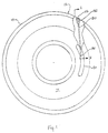
- Fig. 1 is a top view of tire mold part 10.
- the tire mold part 10 will contact and form one sidewall of a tire.
- a second mold part (not illustrated) forms the opposite sidewall, and tread forming segments (also not illustrated) are positioned in the radial direction to the two mold parts.
- the assembled mold parts and tread segments are placed in a press that holds the assembled parts together as they are heated to cure the tire.
- the drawings are not to scale, and the dimensions of various features have been exaggerated or reduced to improve the clarity of the figures.
- the tire mold part 10, and the opposite mold part include aspects that mold information and ornamental features into the tire sidewall.
- the brand name and model of the tire, the tire size, load, and pressure specifications may be molded onto the sidewall.
- Some information for a given tire mold may require occasional change.
- the mold part typically includes a removable plate (not illustrated in Fig. 1) that is inserted in a recess 20 in the mold part 10.
- the invention is directed to a device to allow the quick and easy removal of such plates.
- plates are held in the mold by screws, either mounting from the front or rear of the plate, or by magnets. Removal of plates held by either means is awkward and time consuming.
- a rod 30 is inserted in a hole 22 in the mold part 10.
- the hole 22 extends from an outer surface 12 of the mold part 10 to a position adjacent the recess 20.
- a first end 32 of the rod 30 is disposed at the outer surface 12 so that it may be manipulated to move the rod, as described below.
- a second end 34 of the rod 30 is disposed adjacent the recess 20.
- the rod 30 is movable in the hole 22 to effect release of a plate in the recess 20.
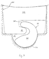
- Fig. 2 is a section view of the mold part of Fig. 1 taken along the lines 2-2 in Fig. 1.
- a plate 50 is inserted the recess 20 in the mold part 10.
- the recess 20 is formed in a side wall ring 14 of the mold part 10.
- the rod 30 extends to a position adjacent the recess 20.
- the rod 30 is rotatable in the hole 22.
- the first end 32 of the rod 30 includes tool engaging means, a hex head hole, a slot, or other suitable structure.
- the second end 34 includes a cam 36, shown in Fig. 3. Turning the rod 30 causes the cam surface 36 to contact and press against the plate 50.
- the cam surface 36 is shaped so that it will push the plate 50 sufficiently free of the recess 20 to be removed by an operator.
- the second end 34 of the rod 30 includes a hook 38 oppositely disposed from the cam surface 36.
- the plate 50 includes a catch 52 that couples with the hook 38 when the rod 30 is rotated appropriately.
- the hook 38 and catch 52 serve to secure the plate in the recess 20.
- FIG. 4 An alternative embodiment is illustrated in Fig. 4.
- the rod 31 is slidable in the hole in the mold part 10, and includes a linear cam 37 formed on the second end 35. By pulling the rod in the left direction in the figure, the linear cam 37 will contact and press on the bottom face 53 of the plate 51, causing it to raise out of the recess 20.
- the rod 31 could, of course, be arranged so that pushing, rather than pulling, causes the linear cam 37 to engage the plate 51.
- a spring or other device could be installed in the hole 22 to bias the rod 31 to a neutral position.
- the slidable rod 31 includes a tab 39 spaced from the linear cam 35 that engages a slot 55 formed in the plate 51 when the rod is moved to a forward position to secure the plate in the recess 20.
- a mold part can have as many removable plates and release devices as needed.
- the present invention is not limited to a particular mold type, and those skilled in the art will understand how to apply the principles of the invention to various molds.
- the described structures and embodiments are meant to be illustrative and not limiting, and those skilled in the art will appreciate that substitutions of equivalents may be made without departing from the scope of the inventions as defined by the following claims.
Landscapes
- Engineering & Computer Science (AREA)
- Mechanical Engineering (AREA)
- Moulds For Moulding Plastics Or The Like (AREA)
Abstract
Description
Claims (11)
- A device for releasing a pocket plate from a recess in a tire mold, comprising a rod insertable in a hole in a tire mold part to extend from a first end at an outer surface of the mold part to a second end at a recess for a pocket plate, the rod being movably supported in the hole, the rod having engaging means at the first end to allow selective manipulation of the rod, and having a cam surface at a second end, wherein selective movement of the rod causes the cam surface to intrude into the recess to press on the pocket plate.
- The release device as claimed in claim 1, wherein the rod is slidable in the hole and the cam surface is linearly arranged on the rod.
- The release device as claimed in claim 2, the rod further comprising a tab for engaging a slot in the pocket plate to secure the pocket plate in the recess.
- The release device as claimed in claim 1, wherein rod is rotatable in the hole and the cam surface is radially arranged on the rod.
- The release device as claimed in claim 4, wherein the engaging means is an axially directed recess in the first end of the rod shaped to engage a tool for rotating the rod.
- The release device as claimed in claim 4, wherein the rod further includes a hook opposite the cam surface for engaging a catch on a back side of the pocket plate by selective rotation of the rod to secure the pocket plate in the recess.
- A tire mold having a pocket plate release device, comprising:A mold half part;a sidewall insert ring supported by the mold half part and having a recess for a pocket plate;a pocket plate releasably mounted in the recess; anda rod inserted through a hole extending from a radially outer surface of the mold half to the pocket, the rod being movably supported in the hole and having engaging means at a first end at the radially outer surface of the mold half to allow selective movement of the rod and having a cam surface at a second end at the recess, wherein selective movement of the rod causes the cam surface to intrude into the recess to push the pocket plate out of the recess.
- The tire mold as claimed in claim 7, wherein the rod is rotatable in the hole, and the engaging means is an axially directed recess in the first end of the rod shaped to engage a tool for rotating the rod.
- The tire mold as claimed in claim 8, wherein the rod further includes a hook opposite the cam and the pocket plate includes on a back side a catch, wherein selective rotation of the rod engages the hook and catch to secure the pocket plate in the recess.
- The release device as claimed in claim 7, wherein the rod is slidable in the hole.
- The release device as claimed in claim 10, wherein the rod includes a tab for engaging a slot in the pocket plate for securing the pocket plate in the recess.
Applications Claiming Priority (2)
| Application Number | Priority Date | Filing Date | Title |
|---|---|---|---|
| US09/525,175 US6315539B1 (en) | 2000-03-14 | 2000-03-14 | Quick release device for a tire mold plate |
| US525175 | 2000-03-14 |
Publications (2)
| Publication Number | Publication Date |
|---|---|
| EP1136217A2 true EP1136217A2 (en) | 2001-09-26 |
| EP1136217A3 EP1136217A3 (en) | 2003-09-17 |
Family
ID=24092236
Family Applications (1)
| Application Number | Title | Priority Date | Filing Date |
|---|---|---|---|
| EP01105889A Withdrawn EP1136217A3 (en) | 2000-03-14 | 2001-03-09 | Quick release device for a tire mold plate |
Country Status (6)
| Country | Link |
|---|---|
| US (1) | US6315539B1 (en) |
| EP (1) | EP1136217A3 (en) |
| JP (1) | JP2001310327A (en) |
| KR (1) | KR20010092283A (en) |
| CA (1) | CA2340502A1 (en) |
| MX (1) | MXPA01002628A (en) |
Cited By (2)
| Publication number | Priority date | Publication date | Assignee | Title |
|---|---|---|---|---|
| CN105451975A (en) * | 2013-08-05 | 2016-03-30 | 米其林企业总公司 | Mould for tyre having a shell with removable parts |
| WO2018200828A1 (en) * | 2017-04-26 | 2018-11-01 | Cooper Tire & Rubber Company | Ball hitch tip out plug, triangle leg tip out plug, combination, and tip out plug tool |
Families Citing this family (12)
| Publication number | Priority date | Publication date | Assignee | Title |
|---|---|---|---|---|
| US6942476B2 (en) * | 2002-08-15 | 2005-09-13 | The Goodyear Tire & Rubber Company | Method and apparatus for changing tire identification means via magnetic inserts |
| US7014446B2 (en) * | 2003-07-14 | 2006-03-21 | Uniloy Milacron Inc. | Quick release volume control inserts for molding machines |
| US8075032B2 (en) * | 2009-08-05 | 2011-12-13 | The Goodyear Tire & Rubber Company | Safety sling for a tire curing machine |
| US7883326B1 (en) * | 2010-01-27 | 2011-02-08 | The Goodyear Tire & Rubber Company | Apparatus and assembly for interchanging indicia of tire molds |
| FR3009229B1 (en) * | 2013-08-05 | 2015-07-17 | Michelin & Cie | PNEUMATIC MOLD HAVING DEMOUNTABLE ANNULAR INSERT |
| FR3009228B1 (en) * | 2013-08-05 | 2015-08-21 | Michelin & Cie | PNEUMATIC MOLD COMPRISING AN ANNULAR INSERT IN SEVERAL PARTS |
| FR3009227B1 (en) * | 2013-08-05 | 2015-08-21 | Michelin & Cie | PNEUMATIC MOLD COMPRISING AN ANNULAR INSERT WITH CONCENTRIC GROOVE |
| FR3017068B1 (en) * | 2014-01-31 | 2017-12-08 | Michelin & Cie | TIRE MOLD WITH A PLATE FOR MOLDING INFORMATION ON THE FLANK OF A TIRE |
| HUE048546T2 (en) * | 2016-06-16 | 2020-07-28 | Mehmet Sueruecue | Plug system with magnetic connection |
| US10632700B2 (en) * | 2017-11-13 | 2020-04-28 | The Goodyear Tire & Rubber Company | Release mechanism for a tire mold plate |
| EP3983210B1 (en) * | 2019-06-13 | 2024-11-06 | Pirelli Tyre S.p.A. | Mould and process for vulcanising tyres for vehicle wheels |
| CN110449514B (en) * | 2019-09-17 | 2020-09-29 | 陈烁 | Universal hardware mould with replaceable mould core |
Family Cites Families (6)
| Publication number | Priority date | Publication date | Assignee | Title |
|---|---|---|---|---|
| US2679663A (en) * | 1950-02-01 | 1954-06-01 | Goodrich Co B F | Marking of molded articles |
| US3739662A (en) * | 1971-01-15 | 1973-06-19 | Matthews J & Co | Retread tire marking method and apparatus |
| JPS5993338A (en) * | 1982-11-18 | 1984-05-29 | Sumitomo Rubber Ind Ltd | Displaying method of data on rubber product |
| US4547139A (en) * | 1984-12-17 | 1985-10-15 | The Goodyear Tire & Rubber Company | Tire mold |
| EP0576892B1 (en) * | 1992-07-02 | 1996-01-10 | Compagnie Generale Des Etablissements Michelin-Michelin & Cie | Tire mould, manufacturing process for such a mould and tire molding process using such a mould |
| US5939002A (en) * | 1997-04-16 | 1999-08-17 | Michelin Recherche Et Technique S.A. | Apparatus and process for changing a sidewall insert of a tire mold |
-
2000
- 2000-03-14 US US09/525,175 patent/US6315539B1/en not_active Expired - Fee Related
-
2001
- 2001-03-09 EP EP01105889A patent/EP1136217A3/en not_active Withdrawn
- 2001-03-12 CA CA002340502A patent/CA2340502A1/en not_active Abandoned
- 2001-03-13 MX MXPA01002628A patent/MXPA01002628A/en unknown
- 2001-03-13 KR KR1020010012841A patent/KR20010092283A/en not_active Withdrawn
- 2001-03-13 JP JP2001071228A patent/JP2001310327A/en not_active Withdrawn
Cited By (7)
| Publication number | Priority date | Publication date | Assignee | Title |
|---|---|---|---|---|
| CN105451975A (en) * | 2013-08-05 | 2016-03-30 | 米其林企业总公司 | Mould for tyre having a shell with removable parts |
| CN105451975B (en) * | 2013-08-05 | 2018-04-03 | 米其林企业总公司 | Tire mold with housing with removable parts |
| WO2018200828A1 (en) * | 2017-04-26 | 2018-11-01 | Cooper Tire & Rubber Company | Ball hitch tip out plug, triangle leg tip out plug, combination, and tip out plug tool |
| KR20190141185A (en) * | 2017-04-26 | 2019-12-23 | 쿠퍼 타이어 앤드 러버 캄파니 | Ball hitch tip out plug, triangle leg tip out plug, combination and tip out plug tool |
| CN110785273A (en) * | 2017-04-26 | 2020-02-11 | 库珀轮胎橡胶公司 | Ball hitch tipping plug, triangular leg tipping plug, combination and tipping plug tool |
| US11220078B2 (en) | 2017-04-26 | 2022-01-11 | Cooper Tire & Rubber Company | Ball hitch tip out plug, triangle leg tip out plug, combination, and tip out plug tool |
| KR102509806B1 (en) | 2017-04-26 | 2023-03-13 | 더 굿이어 타이어 앤드 러버 캄파니 | Ball hitch tip out plug, triangle leg tip out plug, combination and tip out plug tools |
Also Published As
| Publication number | Publication date |
|---|---|
| JP2001310327A (en) | 2001-11-06 |
| MXPA01002628A (en) | 2005-08-26 |
| CA2340502A1 (en) | 2001-09-14 |
| US6315539B1 (en) | 2001-11-13 |
| EP1136217A3 (en) | 2003-09-17 |
| KR20010092283A (en) | 2001-10-24 |
Similar Documents
| Publication | Publication Date | Title |
|---|---|---|
| US6315539B1 (en) | Quick release device for a tire mold plate | |
| EP1389515B1 (en) | Method and apparatus for changing tire identification means via mould inserts | |
| JP2011025698A (en) | Assembly system for moulding unit, and moulding unit with the system | |
| CN105980140B (en) | With the tire-mold for the plate of molding information on side wall | |
| EP3482920B1 (en) | Release mechanism for a tire mold plate | |
| JPH0621843Y2 (en) | Type attaching / detaching device | |
| EP3471940B1 (en) | Plug system with magnetic connection | |
| CN110177680B (en) | Mold elements for tire molds including removable inserts | |
| JPH04126838U (en) | Rubber product mold | |
| US20030041430A1 (en) | Hand tool for brake shoe spring-retaining cup | |
| JP4894522B2 (en) | Manufacturing method of tire mold | |
| JPH0611156Y2 (en) | Mold opening prevention device | |
| KR0140201Y1 (en) | Device for removing a core | |
| JPS61272121A (en) | Molding die | |
| JPH061180Y2 (en) | Pachinko machine locking device | |
| CA2869565C (en) | Multi-piece key assembly | |
| JPH0231237Y2 (en) | ||
| JPH0363494B2 (en) | ||
| JPH0224520Y2 (en) | ||
| JPH07185691A (en) | Auxiliary tool for mold assembly | |
| JPH05250U (en) | Metal ring positioning mechanism for casting | |
| JPH0516252U (en) | Mold clamp mechanism | |
| JPH1052811A (en) | Mold apparatus for formation of concrete product | |
| JPH0677941U (en) | A device that removably fixes a fixing member such as a die to the base. | |
| JPH10291040A (en) | Mold detachment tightening device |
Legal Events
| Date | Code | Title | Description |
|---|---|---|---|
| PUAI | Public reference made under article 153(3) epc to a published international application that has entered the european phase |
Free format text: ORIGINAL CODE: 0009012 |
|
| AK | Designated contracting states |
Kind code of ref document: A2 Designated state(s): AT BE CH CY DE DK ES FI FR GB GR IE IT LI LU MC NL PT SE TR |
|
| AX | Request for extension of the european patent |
Free format text: AL;LT;LV;MK;RO;SI |
|
| PUAL | Search report despatched |
Free format text: ORIGINAL CODE: 0009013 |
|
| AK | Designated contracting states |
Kind code of ref document: A3 Designated state(s): AT BE CH CY DE DK ES FI FR GB GR IE IT LI LU MC NL PT SE TR |
|
| AX | Request for extension of the european patent |
Extension state: AL LT LV MK RO SI |
|
| RIC1 | Information provided on ipc code assigned before grant |
Ipc: 7B 60C 13/00 B Ipc: 7B 29C 33/42 B Ipc: 7B 29D 30/06 B Ipc: 7B 29C 33/30 A |
|
| 17P | Request for examination filed |
Effective date: 20040317 |
|
| AKX | Designation fees paid |
Designated state(s): AT BE CH CY DE DK ES FI FR GB GR IE IT LI LU MC NL PT SE TR |
|
| 17Q | First examination report despatched |
Effective date: 20040428 |
|
| STAA | Information on the status of an ep patent application or granted ep patent |
Free format text: STATUS: THE APPLICATION IS DEEMED TO BE WITHDRAWN |
|
| 18D | Application deemed to be withdrawn |
Effective date: 20051207 |