EP1134952A2 - Internet protocol standards-based multi-media messaging - Google Patents
Internet protocol standards-based multi-media messaging Download PDFInfo
- Publication number
- EP1134952A2 EP1134952A2 EP01302371A EP01302371A EP1134952A2 EP 1134952 A2 EP1134952 A2 EP 1134952A2 EP 01302371 A EP01302371 A EP 01302371A EP 01302371 A EP01302371 A EP 01302371A EP 1134952 A2 EP1134952 A2 EP 1134952A2
- Authority
- EP
- European Patent Office
- Prior art keywords
- server
- telephony
- tip
- port
- ring
- Prior art date
- Legal status (The legal status is an assumption and is not a legal conclusion. Google has not performed a legal analysis and makes no representation as to the accuracy of the status listed.)
- Granted
Links
- 238000004891 communication Methods 0.000 claims abstract description 82
- 238000000034 method Methods 0.000 claims abstract description 52
- 230000004044 response Effects 0.000 claims description 44
- 230000008569 process Effects 0.000 claims description 39
- 230000006870 function Effects 0.000 description 13
- 230000005540 biological transmission Effects 0.000 description 7
- 238000012986 modification Methods 0.000 description 3
- 230000004048 modification Effects 0.000 description 3
- 230000009471 action Effects 0.000 description 2
- 230000005236 sound signal Effects 0.000 description 2
- 238000012546 transfer Methods 0.000 description 2
- 230000001413 cellular effect Effects 0.000 description 1
- 238000010586 diagram Methods 0.000 description 1
- 230000003467 diminishing effect Effects 0.000 description 1
- 230000009977 dual effect Effects 0.000 description 1
- 238000005516 engineering process Methods 0.000 description 1
- 230000003993 interaction Effects 0.000 description 1
- 238000013507 mapping Methods 0.000 description 1
- 238000010615 ring circuit Methods 0.000 description 1
- 238000013519 translation Methods 0.000 description 1
Images



Classifications
-
- H—ELECTRICITY
- H04—ELECTRIC COMMUNICATION TECHNIQUE
- H04M—TELEPHONIC COMMUNICATION
- H04M7/00—Arrangements for interconnection between switching centres
- H04M7/12—Arrangements for interconnection between switching centres for working between exchanges having different types of switching equipment, e.g. power-driven and step by step or decimal and non-decimal
- H04M7/1205—Arrangements for interconnection between switching centres for working between exchanges having different types of switching equipment, e.g. power-driven and step by step or decimal and non-decimal where the types of switching equipement comprises PSTN/ISDN equipment and switching equipment of networks other than PSTN/ISDN, e.g. Internet Protocol networks
-
- H—ELECTRICITY
- H04—ELECTRIC COMMUNICATION TECHNIQUE
- H04M—TELEPHONIC COMMUNICATION
- H04M3/00—Automatic or semi-automatic exchanges
- H04M3/42—Systems providing special services or facilities to subscribers
- H04M3/50—Centralised arrangements for answering calls; Centralised arrangements for recording messages for absent or busy subscribers ; Centralised arrangements for recording messages
- H04M3/53—Centralised arrangements for recording incoming messages, i.e. mailbox systems
- H04M3/533—Voice mail systems
-
- H—ELECTRICITY
- H04—ELECTRIC COMMUNICATION TECHNIQUE
- H04M—TELEPHONIC COMMUNICATION
- H04M3/00—Automatic or semi-automatic exchanges
- H04M3/42—Systems providing special services or facilities to subscribers
- H04M3/487—Arrangements for providing information services, e.g. recorded voice services or time announcements
- H04M3/493—Interactive information services, e.g. directory enquiries ; Arrangements therefor, e.g. interactive voice response [IVR] systems or voice portals
-
- H—ELECTRICITY
- H04—ELECTRIC COMMUNICATION TECHNIQUE
- H04M—TELEPHONIC COMMUNICATION
- H04M7/00—Arrangements for interconnection between switching centres
- H04M7/006—Networks other than PSTN/ISDN providing telephone service, e.g. Voice over Internet Protocol (VoIP), including next generation networks with a packet-switched transport layer
Definitions
- the present invention relates to telecommunications servers, including voice messaging servers.
- voice response servers for use in connection with conventional tip-ring, circuit-based telephone systems.
- voice messaging servers that present a prerecorded greeting to a caller when the telephone of a subscriber is not answered are in wide use. These voice messaging servers typically allow the caller to record an audio message for later retrieval by the subscriber.
- Existing voice messaging servers may also provide a variety of additional functions, such as the ability to contact an operator, or in connection with certain cellular telephones or paging systems, to page the subscriber.
- Other types of voice response servers include automated systems for interacting with callers to receive or distribute information. Most such voice response servers, including voice messaging servers, are adapted for use with traditional telephony techniques, which employ dedicated circuits for transmitting data between the calling telephone and the called telephone or voice response server.
- audible information can be transmitted over computer networks, such as the Internet.
- computer networks divide data into data packets for transmission to the intended recipient over communications channels capable of simultaneously carrying data to many other recipients.
- IP Internet protocol
- the transmission of audible data in packets according to standards such as the Internet protocol (IP) telephony standards e . g ., H.323, H.245 and H.225), eliminates the need to provide a dedicated physical circuit between the endpoints of a communications link, and is therefore more efficient than conventional telephony techniques. Accordingly, Internet telephony type systems are increasingly common.
- servers In order to provide communications servers for use with Internet telephony type systems, vendors have developed servers compatible with such systems. However, such systems are typically not compatible with conventional tip-ring telephony systems. In addition, servers developed for use with Internet telephony systems are typically unable to re-use server hardware and software components previously developed for conventional telephony systems. Accordingly, communications servers for use with Internet telephony systems have limited applicability, and are expensive to develop.
- a communications server is interfaced with a computer network to enable the server to service telephone calls placed using an Internet telephony type communications channel.
- the communications server is provided with a software module for mapping data events expressed using Internet protocol standards to corresponding events and the expression of such events in a traditional circuit-based communications system.
- the present invention utilizes a communications server originally adapted for use with a tip-ring, circuit-based telephony network.
- the communications server is provided with an interface for interconnecting the server to a computer network using a packet-based data communications protocol.
- the communications server is provided with a port interface for assigning ports on the server to virtual channels established over the computer network, and an Internet protocol process module that includes functions for translating between events expressed according to a tip-ring type telephony network, and commands transmitted according to a packet-based computer network.
- an existing server adapted for use with a tip-ring type telephony communications server may be modified so that it can service communications transmitted using a packet-based, or Internet protocol, computer network.
- an existing tip-ring server may be modified by replacing the server's existing port interface library with a port interface library as disclosed by the present invention, and by adding Internet protocol telephony software and hardware for interfacing the server to an Internet protocol network.
- the present invention allows the application software of an existing tip-ring server to operate in connection with an IP protocol telephony network by providing software that presents the application software with a consistent interface, regardless of whether a particular call being serviced is connected to the server at a tip-ring or IP network interface.
- the ability of the server to service tip-ring type telephony communications may be maintained. Accordingly, the present invention enables service providers to upgrade their service offerings without needing to replace existing servers.
- the present invention provides communications servers capable of servicing communications transmitted over a tip-ring type telephony network and communications transmitted over a packet-based computer network simultaneously.
- a communications server 100 is illustrated, including an illustrative system topology surrounding the communications server 100.
- the arrangement generally comprises the communications server 100, a computer network 102, and a continuous circuit-based telephony system 104.
- the computer network 102 may be any local area network (LAN) or wide area network (WAN).
- the computer network 102 may be the public Internet or a private intranet.
- the computer network 102 is characterized by its use of data packets, arranged according to a defined protocol, for the delivery of communications across the network 102.
- the computer network 102 may be interconnected to a soft phone, audio enabled personal computer 106, or other type of endpoint, such as an Internet protocol (IP) end point. Accordingly, the computer network 102 may be used to transmit communications between the soft phone 106 and some other end point, such as a second soft phone (not shown in Fig. 1) or the communications server 100 according to Internet protocol telephony standards.
- IP Internet protocol
- the tip-ring, continuous circuit telephone network 104 may be the public switched telephone network (PSTN).
- the tip-ring telephony system 104 may be a private branch exchange (PBX).
- PBX private branch exchange
- the tip-ring telephony system 104 may also comprise digital circuit based communications systems such as the T1 system. Accordingly, the interface between the tip-ring telephony system 104 and the communications server 100 employs switched circuit telephony standards.
- Interconnected to the tip-ring telephony system 104 may be a telephone 108 or other communications device.
- the communications device 108 may be a telephone that can be interconnected to the communications server 100 through the telephony system 104 using well known continuous circuit techniques. However, it should be understood that the telephone 108 may be interconnected to the communications server through any combination of communications systems.
- the communications server 100 may be any telephony communications server, including voice response servers and messaging servers, such as the Intuity AudixTM or AnyPathTM messaging systems or ConversantTM voice response systems of Lucent Technologies Inc.
- the communications server 100 is generally a stored program controlled apparatus, having a processor 110 for executing control programs stored in storage 112. Storage 112 may be any computer readable storage medium.
- the communications server 100 also includes a network interface 114 for interconnecting the communications server 100 to the computer network 102.
- the communications server 100 may also be provided with tip-ring telephony ports 116 for interconnecting the communications server 100 to the tip-ring telephony network 104.
- the storage 112 may contain a database 118 for storing administrative information.
- the database 118 may provide message mailboxes for each subscriber of the messaging service and for storing associated information, such as subscriber greetings and subscriber passwords.
- the storage 112 may also include a variety of software modules.
- the storage 112 generally includes a voice response application software module 120 for controlling the interaction of the communications server 100 with users who establish communications with the server 100.
- the application software 120 may provide an interface to subscribers and those persons attempting to contact the subscriber whose calls have been redirected to the server 100.
- the application software 120 may include the programming necessary to play back subscriber greetings, record caller messages, and otherwise provide the rich set of features associated with such servers 100 .
- the application software 120 is adapted to communicate with other software modules (described below) using a predetermined set of commands.
- This predetermined set of commands may be any type of interprocess message, such as a standard UNIX operating system IPC message queue type interprocess message.
- the storage 112 also contains a port interface library 122, a tip-ring device driver 124, an Internet protocol (IP) interface process 126, an IP telephony stack 128, and a TCP/IP stack 130.
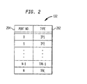
- the port interface library 122 may include a port map 132 and an event queue 134.
- the port map 132 maps the ports available on the voice response application software 120 to those handling communications transmitted over the tip-ring telephony system 104, and to those handling communications transmitted over the computer network 102.
- the allocation of ports in the port map 132 to the tip-ring telephony system 104 or the computer network 102 may be determined by the administrator of the server 100, or may be performed dynamically according to demand.
- the event queue 134 serves as a buffer for asynchronous events received from the tip-ring device driver 124 or the IP interface process module 126.
- the tip-ring device driver 124 contains the programming commands necessary to control the tip-ring interface hardware 116.
- the tip-ring device driver 124 in response to events received from the port interface library 122 that are formatted according to the predetermined set of commands, controls the tip-ring interface hardware 116 in accordance with those events.
- the tip-ring interface hardware also formats data passed to it from the port interface library 122 for transmission across the tip-ring telephony system 104.
- the tip-ring device driver 124 operates to receive data and events from the tip-ring telephony system 104 and to format data and events according to the predetermined set of commands and pass the formatted data and events to the port interface library 122.
- the tip-ring device driver 124 serves to control the tip-ring hardware 116, and that commands and data that pass between the tip-ring device driver 126 and the port interface library 122 are formatted according to the conventions of the predetermined set of commands.
- the IP interface process 126 generally serves as an interface and a translation module to translate between the port interface library 122 and the IP telephony stack 128 associated with the network interface 114.
- the IP interface process 126 communicates with the application software 120 using the application software's 120 predetermined set of commands, and with the IP telephony stack 128 using packets of data, as required by the IP telephony stack 128.
- the network interface 114 serves as the physical interface between the computer network 102 and the TCP/IP stack 130. Data packets received at the TCP/IP stack 130 are passed to the IP telephony stack 128.
- the IP telephony stack 128 may be any protocol for the transmission of voice, fax and data communications over computer networks, including the Internet, such as the H.323, H.245 and H.225 standards established by the International Telecommunications Union.
- the IP telephony stack 128 then provides the data, still in the form of packets, to the IP interface process 126.
- communication streams transmitted over the computer network 102 are not assigned to dedicated physical circuits. Instead, data associated with each stream is placed into packets for transmission over a shared communication channel. Because of the lack of dedicated circuits in the computer network 102 environment, individual communication streams must be assigned to virtual ports.
- a virtual port map 136 is therefore included as part of the Internet protocol interface process 126, to enable the IP interface process module 126 to attribute particular communication streams to particular ports in communicating with the port interface library 122.
- the port map 132 generally contains information regarding the type of communication channel 202 associated with each port available in connection with the voice response application software 120.
- port numbers 0 and 1 are both associated with Internet protocol communications. Therefore, data and events originating from the voice response application software 120 in connection with ports 0 and 1 will be forwarded by the port interface library 122 to the IP interface process module 126.
- Port numbers n-1 and n are, in the example illustrated in Fig. 2, associated with the tip-ring telephony system 104.
- events and data originating from the voice response application software 120 in connection with ports n-1 and n will be forwarded by the port interface library 122 to the tip-ring device driver 124 for transmission across the tip-ring telephony system 104.
- Commands and data received by the IP interface process module 126 from the computer network 102 are associated with the appropriate port number, and translated into the predetermined set of commands used by the voice response application software 120 to communicate with other software modules before being passed to the port interface library 122.
- Commands and data received by the tip-ring device driver 124 from the tip-ring telephony network 104 are also formatted before they are passed to the appropriate port on the voice response application software 120.
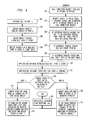
- a flow chart of the operation of the server 100 in answering a telephone call is shown.
- an example of the operation of the server 100 in response to an incoming call received at port n of the tip-ring hardware 116 (step 302 ) will be explained.
- the operation of the server 100 in response to an incoming call received at the network interface 114 will be explained.
- the tip-ring device driver 124 at step 304, detects the ringing circuit at port n.
- the device driver 124 in response to the ringing circuit, creates a NEW_CALL(port n) event at step 306, which is placed in the event queue 134 of the port interface library 122 at step 308.
- the new call event is received by the voice response application software 120 via a GET_EVENT() function call initiated by the application software 120 at step 310.
- the application software 120 issues an OFF_HOOK(port n) command to the port interface library 122 to place port n off hook at step 312.
- the port interface library 122 consults the port map 132 to determine the type of interface associated with port n.
- port n is a tip-ring port
- the port interface library 122 directs the OFF_HOOK(port n) command to the tip-ring device driver 124 to place port n (step 316 ) off hook.
- the tip-ring device driver 124 takes port n off hook, establishing a physical circuit between the telephony system 104 end point ( e . g ., telephone 108 ) and the device driver of the tip-ring hardware 116 for port n.
- the application software 120 may then begin its normal call-answer scenario at step 320, such as playing a greeting and allowing the calling party to record a message in a subscriber mailbox, etc.
- a call connection request is received at the network interface 114 as a packet of data.
- the call connection request is passed to the TCP/IP stack 130 to the Internet protocol telephony stack 128, and is then delivered to the Internet protocol interface process 126 (step 324 ).
- the IP interface process 126 recognizes the data packet to be a call connection request, assigns the incoming call to an available virtual port at step 326, and updates the virtual port map 136 to indicate that the assigned port is busy.
- the IP interface process 126 may assign the call to port 0, and mark port 0 as busy in the virtual port map 136.
- the IP interface process 126 creates a NEW_CALL(port 0) event, and places the new call event in the event queue 134 of the port interface library 122 at step 330.
- the application software 120 retrieves the new call event via a GET_EVENT() function call at step 310.
- the application software 120 then issues an OFF_HOOK(port 0) command to place port 0 off hook at step 312.
- the port interface library 122 Upon receipt of the command to place port 0 off hook, the port interface library 122 consults the port map 132 at step 314 to determine whether port 0 is a tip-ring or IP telephony type port. In the present example, port 0 is an IP telephony port, therefore, the port interface library 122 directs the OFF_HOOK(port 0) command to the Internet protocol interface process 126 to place port 0 off hook at step 332.
- the IP interface process 126 upon receipt of the off hook command, sends an accept call message to the Internet protocol endpoint 106 at step 334.
- the Internet protocol interface 126 then exchanges connection information with the IP endpoint 106 ( i . e . completes handshake procedures) and establishes a logical channel and a remote transfer protocol (RTP) session, also at step 334 .
- RTP remote transfer protocol
- the server 100 of the present invention is capable of servicing connections established over either the PSTN 104 or the computer network 102.
- the voice response application software 120 is the same, regardless of whether the communication channel used is the PSTN 104 or a computer network 102.
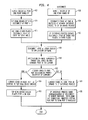
- a flow chart of the operation of the server 100 in disconnecting from established telephone calls is shown.
- the operation of the server 100 in response to a disconnect event initiated by a remote caller connected to the server 100 over the PSTN 104 will be explained.
- the remote caller initiates a disconnect by hanging up the telephone 108.
- the tip-ring driver 124 detects the disconnect signal at port n.
- the tip-ring driver 124 places a DISCONNECT(port n) event in the event queue 134 of the port interface library 122 (step 406 ).
- the DISCONNECT(port n) event is then passed to the application software 120 via a GET_EVENTO function call initiated by the application software 120 at step 408.
- the application software 120 terminates the transaction, and sends an ON_HOOK(port n) command to the port interface library 122 at step 410.
- the library 122 consults the port map 132 to determine how to route the ON_HOOK(port n) command.
- port n is associated with a tip-ring port, therefore the library 122 sends the ON_HOOK(port n) command to the tip-ring device driver 124 at step 414.
- the tip-ring device driver 124 places port n on hook at step 416, concluding the disconnect operation.
- the remote caller at the Internet protocol endpoint 106 hangs up.
- the remote caller may "hang up" the end point 106 by, for example, clicking on a button presented by a graphical user interface of a communication program associated with a personal computer or other device.
- a data packet containing a disconnect event for port 0 is received at the network interface 114, and is passed to the IP interface process 126.
- the IP interface process 126 reads the received packet of data, and in response formats a DISCONNECT(port 0) event and places that event in the event queue 134 at step 422.
- the voice response application software 120 retrieves the DISCONNECT(port 0) event from the event queue 134 through a GET_EVENT() function call at step 408.
- the application software 120 terminates the transaction for port 0 and sends an ON_HOOK(port 0) command to the port interface library 122 at step 410 .
- the library then consults the port map to determine the proper recipient of the event at step 412.
- the ON_HOOK(port 0) command is sent to the IP interface process 126 at step 424.
- the IP interface process 126 sends acknowledgment of the disconnect to the remote end point 106, tears down the remote transfer process (RTP) connection, and modifies the virtual port map 136 to show port 0 available at step 426, completing the disconnect sequence.
- RTP remote transfer process
- the server 100 of the present invention allows existing voice response application software 120 to be used in connection with either communications taking place over the PSTN 104, or those transmitted across a computer network 102 such as the Internet.
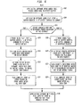
- the server 100 detects a dual tone multiple frequency (DTMF) signal at port n of the tip-ring hardware 116.
- the device driver 124 formats a TOUCH_TONE(port n, value x) event at step 504, where the value x is related to the key pressed on the keypad of the telephone 108 ( e . g ., 1, 2, 3, 4, 5, 6, 7, 8, 9, 0, * or #).
- the device driver 116 then places the TOUCH_TONE(port n, value x) event in the event queue 134 of the port interface library 122 at step 506.
- the application software 120 retrieves the TOUCH_TONE(port n, value x) event through a GET_EVENT( ) function call made to the event queue 134.
- the application software 120 then performs a prescribed action in response to receipt of the value x at step 510.
- the application software 120 may connect the caller to an operator upon receipt of a touch tone value for zero.
- the touch tone event is received as a data packet at the network interface 114 (step 512 ).
- the touch tone event data packet is passed to the TCP/IP stack 130, to the IP telephony stack 128, and finally to the IP interface process 126 at step 514.
- the IP interface process 126 recognizes the data packet as a touch tone event at a port, for example, port 0.
- the touch tone event may be communicated to the IP interface process 126 using an in-band (for example, DTMF tone data embedded in the RTP audio stream) or out of band signal (for example, an H.245 protocol user input indication message).
- the IP interface process 126 creates a TOUCH_TONE(port 0, value x) event.
- the IP interface process 126 places the TOUCH_TONE(port 0, value x) event in the event queue 124 at step 518.
- the application software 120 retrieves the TOUCH_TONE(port 0, value x) event through a GET_EVENT() function call at step 508.
- the application software may then perform an action in response to the value x received at step 510.
- the TOUCH_TONE(port #, value x) event appears the same to the application software 120, regardless of the communication channel over which the server 100 received the event or command. Accordingly, the application software 120 need not be modified in order to operate in connection with a computer network 102. All that is required is that the server 100 be provided with a port map 132, an IP interface process 126, and an associated Internet protocol device drivers and hardware.
- the application software 120 opens an audio file stored on database 118, and places the audio data contained in that file in a memory buffer.
- the application software 120 next sends a PLAY(port #, buffer address, number of bytes) command to the library 122 at step 604.
- These steps are taken by the application software 120 regardless of whether the port with which the play command is associated is a tip-ring or IP telephony port. Indeed, the port type is transparent to the application software 120.
- the library 122 consults the port map 132 to determine the proper routing for the play command.
- the play command will be routed to the tip-ring device driver 124 (step 608 ).
- the tip-ring device driver 124 reads the audio data at the buffer address specified as part of the play command into memory associated with the tip-ring hardware 116 at step 610.
- the tip-ring hardware 116 then sends the audio data to the tip-ring device driver 124, and the audio data is sent as an audible signal to the remote caller over the physical tip-ring circuit established across the PSTN 104 (step 612 ).
- the tip-ring device driver 124 places a PLAY_COMPLETE(port n) event in the event queue 134.
- the application software 120 retrieves the PLAY_COMPLETE(port n) event through a GET_EVENT() function call and sends the next play request to the library 122, or terminates the play sequence.
- the steps taken by the application software 120 to initiate play of an audio message are the same where the message is to be transmitted over the computer network 102.
- the application software 120 opens an audio file, and places audio data from that file in a memory buffer.
- the application software sends the play command to the library 122.
- the play command here references an IP telephony port.
- the command is PLAY(port 0, buffer address, number of bytes).
- the library 122 consults the port map 132 at step 606 to determine the proper recipient of the play event.
- port 0 is an IP telephony port, thus the library sends the PLAY(port 0, buffer address, number of bytes) command to the IP interface process 126 at step 618.
- the IP interface process 126 retrieves the audio data from the memory buffer and places that data in data packets for transmission to the remote IP endpoint 106 (step 620 ).
- the data packets containing the audio data are sent to the IP end point 106 using RTP/RTCP standard communication protocol, where the data is reassembled and played out as an audible signal to the caller.
- the IP interface process 126 issues a PLAY_COMPLETE(port 0) event, and places that event in the event queue 134 (step 624 ).
- the application software 120 then retrieves the PLAY_COMPLETE(port 0) event through a GET_EVENT() function call, and sends out the next play request or terminates the play sequence at step 616 .
- a server 100 in response to the command to record audio signal from a caller is illustrated.
- the application software 120 allocates a memory buffer to receive the audio data.
- the application software 120 then sends a RECORD(port #, buffer address, number of bytes)command to the library 122 at step 704. These steps are taken by the application software without regard to whether the audio data will be recorded from a tip-ring or IP telephony port.
- the library 122 consults the port map 132 to determine where the record event should be routed at step 706.
- the record command will be routed to the tip-ring device driver 124 (step 708 ).
- the tip-ring device driver 124 then stores the incoming audio stream from the tip-ring hardware 116 in the allocated memory buffer until the buffer is full or the application software 120 instructs the tip-ring device driver to stop recording (step 710 ).
- the tip-ring device driver 124 returns a RECORD_COMPLETE(port n, #bytes) event to the event queue 134 at step 712.
- the application software 120 retrieves the RECORD_COMPLETE (port n, # bytes) event through a GET_EVENT() function call and stores the audio data in the database 118 (step 714 ).
- the steps taken by the application software 120 to record incoming audio data are the same where the audio data is received at the network interface 114. Accordingly, at step 702 the application software 120 allocates a memory buffer to receive the audio data. At step 704, the application software 120 sends a RECORD(port 0, buffer address, # bytes) command ( e . g . where port 0 is allocated to an IP telephony port) to the library 122. The library 122 then consults the port map 132 to determine where the command should be routed at step 706. In the present example, port 0 is an IP telephony port, so the command is directed to the interface process 126 (step 716 ).
- the IP interface process 126 stores the incoming audio stream in the allocated memory buffer until the buffer is full or the IP interface process 126 is instructed to otherwise stop recording data (step 718 ).
- the IP interface process 126 next returns a RECORD_COMPLETE(port 0, # bytes) event to the event queue (step 720 ).
- the application software 120 retrieves the RECORD_COMPLETE (port 0, # bytes) event through a GET_EVENT() function call and stores the audio data in the database 118 at step 714.
- a server 100 may use preexisting application software 120 in connection with communications transmitted over a computer network 102, such as the Internet
- the communications server 100 need not be connected to a tip-ring telephony system 104.
- Such variations can be made without departing from the spirit and the scope of the invention and without diminishing its attendant advantages, and it is intended that such variations be covered by the appended claims.
Landscapes
- Engineering & Computer Science (AREA)
- Signal Processing (AREA)
- Computer Networks & Wireless Communication (AREA)
- Telephonic Communication Services (AREA)
- Data Exchanges In Wide-Area Networks (AREA)
- Communication Control (AREA)
- Interface Circuits In Exchanges (AREA)
Abstract
Description
Claims (20)
- A communications apparatus, comprising:
a communications server for servicing physical circuits established over a continuous circuit telephony system, comprising:a computer network interface for interconnecting said server to a computer network;a voice response application module for providing communications services;a port interface library module for assigning a server channel to a virtual communications channel established over said computer network; andan Internet protocol interface process module interconnected to said computer network interface and to said port interface library, wherein said Internet protocol interface process module communicates with said port interface library using a first set of commands, and wherein said Internet protocol interface process module communicates with said computer network interface using a second set of commands expressed in a packet-based format. - The apparatus of Claim 1, wherein said server further comprises:an interface for interconnecting said server to a continuous circuit telephony system; anda continuous circuit telephone system device driver interconnected to said continuous circuit telephony system interface and to said port interface library, wherein said continuous circuit telephony system interface communicates with said port interface library using said first set of commands, and wherein said port interface library module assigns a server channel to a physical communications channel established over said continuous circuit telephony system.
- The apparatus of Claim 2, wherein said interface for interconnecting said server to a continuous circuit telephony system is a tip-ring telephony interface.
- The apparatus of Claim 1, wherein said server is a voice response server.
- The apparatus of Claim 1, wherein said server is a unified communications server.
- The apparatus of Claim 1, wherein said server is a unified messaging server.
- The apparatus of Claim 1, wherein said computer network is the Internet.
- The apparatus of Claim 2, wherein said continuous circuit telephony system is the public switched telephony network.
- The apparatus of Claim 2, wherein said continuous circuit telephony system is a private branch exchange.
- An Internet protocol voice response system, comprising:a communications server adapted for use with a tip-ring telephony system;means for operatively connecting said server to an Internet protocol computer network;means for translating between tip-ring telephony system events and Internet protocol telephony commands, wherein said means for translating serves to operably connect said communications server to said Internet protocol computer network; andmeans for allocating channels available on said communications server to virtual communications channels established over said Internet protocol computer network.
- The system of Claim 10, further comprising:a tip-ring telephony network; andmeans for operatively connecting said communications server to a tip-ring telephony network, wherein said means for allocating channels available on said communications server allocates said channels between virtual communications channels established over said Internet protocol computer network and physical channels established over said tip-ring telephony network.
- The system of Claim 10, wherein said Internet protocol computer network is the Internet
- The system of Claim 11, wherein said tip-ring telephony network is the public switched telephony network.
- The system of Claim 11, wherein said tip-ring telephony network is a private branch exchange.
- A method for interfacing a tip-ring telephony server to a packet-based communications network, comprising:receiving a first signal at an interface between a tip-ring telephony server and a computer network, wherein said signal is at least one of a packet of data and a software event;translating said first signal into a second signal format, wherein said second signal format is the other of a packet of data and a software event; andperforming at least one of the following steps:a) providing said second signal, formatted as a software event, to said tip-ring telephony server when said computer network is the source of said first signal, andb) providing said second signal, formatted as a packet of data, to said computer network when said tip-ring telephony server is the source of said first signal.
- The method of Claim 15, further comprising assigning channels available on said server to virtual channels established over said packet-based network.
- The method of Claim 15, further comprising:interfacing said server with a tip-ring telephony network; andallocating channels available on said server between virtual channels established over said packet-based network and physical channels established over said tip-ring telephony network.
- The method of Claim 15, wherein said packet-based network is the Internet.
- The method of Claim 17, wherein said tip-ring telephony network is the public switched telephony network.
- The method of Claim 18, wherein said tip-ring telephony network is a private branch exchange.
Applications Claiming Priority (2)
| Application Number | Priority Date | Filing Date | Title |
|---|---|---|---|
| US524881 | 2000-03-14 | ||
| US09/524,881 US6999448B1 (en) | 2000-03-14 | 2000-03-14 | Internet protocol standards-based multi-media messaging |
Publications (3)
| Publication Number | Publication Date |
|---|---|
| EP1134952A2 true EP1134952A2 (en) | 2001-09-19 |
| EP1134952A3 EP1134952A3 (en) | 2003-11-19 |
| EP1134952B1 EP1134952B1 (en) | 2005-05-11 |
Family
ID=24091037
Family Applications (1)
| Application Number | Title | Priority Date | Filing Date |
|---|---|---|---|
| EP01302371A Expired - Lifetime EP1134952B1 (en) | 2000-03-14 | 2001-03-14 | Internet protocol standards-based multi-media messaging |
Country Status (5)
| Country | Link |
|---|---|
| US (1) | US6999448B1 (en) |
| EP (1) | EP1134952B1 (en) |
| JP (1) | JP4142265B2 (en) |
| KR (1) | KR20010092273A (en) |
| DE (1) | DE60110669T2 (en) |
Cited By (1)
| Publication number | Priority date | Publication date | Assignee | Title |
|---|---|---|---|---|
| GB2417394A (en) * | 2004-01-29 | 2006-02-22 | Samsung Electronics Co Ltd | Storing voice messages in packet form in a VoIP voice mail box |
Families Citing this family (7)
| Publication number | Priority date | Publication date | Assignee | Title |
|---|---|---|---|---|
| EP1305936B1 (en) * | 2000-07-31 | 2008-10-08 | Nokia Siemens Networks Gmbh & Co. Kg | Device and method for call diversion in telecommunication networks |
| US7454505B2 (en) * | 2001-01-25 | 2008-11-18 | International Business Machines Corporation | Communication endpoint supporting multiple provider models |
| JP4700204B2 (en) * | 2001-03-07 | 2011-06-15 | 株式会社日立製作所 | Storage management data control system |
| JP4718791B2 (en) * | 2004-04-16 | 2011-07-06 | Necインフロンティア株式会社 | DTMF tone signal transmission method and DTMF tone signal transmission system |
| US8615396B2 (en) * | 2008-09-02 | 2013-12-24 | International Business Machines Corporation | Voice response unit mapping |
| US8290125B2 (en) * | 2008-09-02 | 2012-10-16 | International Business Machines Corporation | Voice response unit shortcutting |
| US9106745B2 (en) * | 2008-09-16 | 2015-08-11 | International Business Machines Corporation | Voice response unit harvesting |
Family Cites Families (17)
| Publication number | Priority date | Publication date | Assignee | Title |
|---|---|---|---|---|
| US5463670A (en) * | 1992-10-23 | 1995-10-31 | At&T Ipm Corp. | Testing of communication services and circuits |
| GB2280820A (en) * | 1993-07-29 | 1995-02-08 | Ibm | Distributed system for call processing |
| US5884262A (en) * | 1996-03-28 | 1999-03-16 | Bell Atlantic Network Services, Inc. | Computer network audio access and conversion system |
| US6122255A (en) * | 1996-04-18 | 2000-09-19 | Bell Atlantic Network Services, Inc. | Internet telephone service with mediation |
| SE506775C2 (en) * | 1996-06-04 | 1998-02-09 | Ericsson Telefon Ab L M | Ways and devices for simultaneous telephone and Internet connection on a telephone line |
| US6282511B1 (en) | 1996-12-04 | 2001-08-28 | At&T | Voiced interface with hyperlinked information |
| US6542497B1 (en) * | 1997-03-11 | 2003-04-01 | Verizon Services Corp. | Public wireless/cordless internet gateway |
| CA2286338A1 (en) | 1997-04-22 | 1998-10-29 | Telcordia Technologies, Inc. | Apparatus and method for internet telephony routing |
| US6188688B1 (en) * | 1997-05-21 | 2001-02-13 | International Business Machines Corporation | Method and apparatus for placing telephone calls while connected to the internet |
| US6233234B1 (en) * | 1997-06-03 | 2001-05-15 | Bell Atlantic Network Services, Inc. | Secure LAN/internet telephony |
| EP0921659B1 (en) | 1997-06-18 | 2005-08-17 | Kabushiki Kaisha Toshiba | Multimedia information communication system |
| JPH11163922A (en) | 1997-11-28 | 1999-06-18 | Nec Corp | Communication information transfer method for multi media and storage conversion system |
| US6349133B1 (en) * | 1998-04-15 | 2002-02-19 | Premisenet Incorporated | Method and system for interfacing a telephony network and a digital data stream |
| US6430175B1 (en) * | 1998-05-05 | 2002-08-06 | Lucent Technologies Inc. | Integrating the telephone network and the internet web |
| EP0964567A3 (en) | 1998-06-12 | 2002-01-02 | Alcatel USA Sourcing, L.P. | A programmable telecommunications interface for communication over a data network |
| US6269336B1 (en) * | 1998-07-24 | 2001-07-31 | Motorola, Inc. | Voice browser for interactive services and methods thereof |
| GB2348566A (en) * | 1999-03-31 | 2000-10-04 | Ibm | Computer network telephony |
-
2000
- 2000-03-14 US US09/524,881 patent/US6999448B1/en not_active Expired - Lifetime
-
2001
- 2001-03-13 KR KR1020010012803A patent/KR20010092273A/en not_active Withdrawn
- 2001-03-14 EP EP01302371A patent/EP1134952B1/en not_active Expired - Lifetime
- 2001-03-14 DE DE60110669T patent/DE60110669T2/en not_active Expired - Fee Related
- 2001-03-14 JP JP2001071340A patent/JP4142265B2/en not_active Expired - Fee Related
Cited By (2)
| Publication number | Priority date | Publication date | Assignee | Title |
|---|---|---|---|---|
| GB2417394A (en) * | 2004-01-29 | 2006-02-22 | Samsung Electronics Co Ltd | Storing voice messages in packet form in a VoIP voice mail box |
| GB2417394B (en) * | 2004-01-29 | 2007-11-14 | Samsung Electronics Co Ltd | Voice messaging service in voice over internet protocol (voip) system |
Also Published As
| Publication number | Publication date |
|---|---|
| DE60110669T2 (en) | 2006-04-27 |
| JP2001333185A (en) | 2001-11-30 |
| KR20010092273A (en) | 2001-10-24 |
| EP1134952B1 (en) | 2005-05-11 |
| DE60110669D1 (en) | 2005-06-16 |
| EP1134952A3 (en) | 2003-11-19 |
| JP4142265B2 (en) | 2008-09-03 |
| US6999448B1 (en) | 2006-02-14 |
Similar Documents
| Publication | Publication Date | Title |
|---|---|---|
| US7787611B1 (en) | Packet telephony bridging server | |
| US6600733B2 (en) | System for interconnecting packet-switched and circuit-switched voice communications | |
| US6118864A (en) | System and method for providing communication on a wide area network | |
| JP4125806B2 (en) | Communication routing apparatus and method | |
| KR100372036B1 (en) | Dual phone | |
| AU708959B2 (en) | Method to provide voice call notification and control messaging over a data path | |
| US6532286B1 (en) | Method and system for processing a telephone call | |
| US9264544B2 (en) | Automated attendant multimedia session | |
| US7369544B2 (en) | Internet telephone system with hunting diversion | |
| US6188688B1 (en) | Method and apparatus for placing telephone calls while connected to the internet | |
| EP0901297B1 (en) | Method and device for call transfer to an agent station | |
| JPH11511302A (en) | Call setup server | |
| JP2000500297A (en) | Call setup server | |
| US6999448B1 (en) | Internet protocol standards-based multi-media messaging | |
| GB2351869A (en) | Voice processing system | |
| US8160227B1 (en) | System and method for establishing roaming line numbers | |
| CN100559816C (en) | Software call control agent | |
| WO1998051115A2 (en) | Method and apparatus for using the d channel for controlling the b channels in an isdn connection | |
| IL124033A (en) | Communication systems | |
| JP2002528012A (en) | Telecommunications network and method for establishing a connection between parties | |
| HK1056274A (en) | Method to provide voice call notification and control messaging over a data path | |
| EP1290818A1 (en) | System providing integrated services over a computer network |
Legal Events
| Date | Code | Title | Description |
|---|---|---|---|
| PUAI | Public reference made under article 153(3) epc to a published international application that has entered the european phase |
Free format text: ORIGINAL CODE: 0009012 |
|
| AK | Designated contracting states |
Kind code of ref document: A2 Designated state(s): AT BE CH CY DE DK ES FI FR GB GR IE IT LI LU MC NL PT SE TR |
|
| AX | Request for extension of the european patent |
Free format text: AL;LT;LV;MK;RO;SI |
|
| RIN1 | Information on inventor provided before grant (corrected) |
Inventor name: KLEIN, ROBERT M. |
|
| PUAL | Search report despatched |
Free format text: ORIGINAL CODE: 0009013 |
|
| AK | Designated contracting states |
Kind code of ref document: A3 Designated state(s): AT BE CH CY DE DK ES FI FR GB GR IE IT LI LU MC NL PT SE TR |
|
| AX | Request for extension of the european patent |
Extension state: AL LT LV MK RO SI |
|
| RIC1 | Information provided on ipc code assigned before grant |
Ipc: 7H 04M 7/00 B Ipc: 7H 04L 29/06 A Ipc: 7H 04M 3/51 B |
|
| 17P | Request for examination filed |
Effective date: 20040312 |
|
| GRAP | Despatch of communication of intention to grant a patent |
Free format text: ORIGINAL CODE: EPIDOSNIGR1 |
|
| AKX | Designation fees paid |
Designated state(s): DE FR GB |
|
| GRAS | Grant fee paid |
Free format text: ORIGINAL CODE: EPIDOSNIGR3 |
|
| GRAA | (expected) grant |
Free format text: ORIGINAL CODE: 0009210 |
|
| AK | Designated contracting states |
Kind code of ref document: B1 Designated state(s): DE FR GB |
|
| REG | Reference to a national code |
Ref country code: GB Ref legal event code: FG4D |
|
| REG | Reference to a national code |
Ref country code: IE Ref legal event code: FG4D |
|
| REF | Corresponds to: |
Ref document number: 60110669 Country of ref document: DE Date of ref document: 20050616 Kind code of ref document: P |
|
| PLBE | No opposition filed within time limit |
Free format text: ORIGINAL CODE: 0009261 |
|
| STAA | Information on the status of an ep patent application or granted ep patent |
Free format text: STATUS: NO OPPOSITION FILED WITHIN TIME LIMIT |
|
| ET | Fr: translation filed | ||
| 26N | No opposition filed |
Effective date: 20060214 |
|
| REG | Reference to a national code |
Ref country code: GB Ref legal event code: 732E Free format text: REGISTERED BETWEEN 20090430 AND 20090506 |
|
| PGFP | Annual fee paid to national office [announced via postgrant information from national office to epo] |
Ref country code: GB Payment date: 20090311 Year of fee payment: 9 |
|
| PGFP | Annual fee paid to national office [announced via postgrant information from national office to epo] |
Ref country code: DE Payment date: 20090313 Year of fee payment: 9 |
|
| PGFP | Annual fee paid to national office [announced via postgrant information from national office to epo] |
Ref country code: FR Payment date: 20090316 Year of fee payment: 9 |
|
| GBPC | Gb: european patent ceased through non-payment of renewal fee |
Effective date: 20100314 |
|
| REG | Reference to a national code |
Ref country code: FR Ref legal event code: ST Effective date: 20101130 |
|
| PG25 | Lapsed in a contracting state [announced via postgrant information from national office to epo] |
Ref country code: FR Free format text: LAPSE BECAUSE OF NON-PAYMENT OF DUE FEES Effective date: 20100331 |
|
| PG25 | Lapsed in a contracting state [announced via postgrant information from national office to epo] |
Ref country code: DE Free format text: LAPSE BECAUSE OF NON-PAYMENT OF DUE FEES Effective date: 20101001 |
|
| PG25 | Lapsed in a contracting state [announced via postgrant information from national office to epo] |
Ref country code: GB Free format text: LAPSE BECAUSE OF NON-PAYMENT OF DUE FEES Effective date: 20100314 |