EP1134945A1 - Method to determine a channel characteristic, and discrete wavelet transmitter and receiver to perform the method - Google Patents
Method to determine a channel characteristic, and discrete wavelet transmitter and receiver to perform the method Download PDFInfo
- Publication number
- EP1134945A1 EP1134945A1 EP00400620A EP00400620A EP1134945A1 EP 1134945 A1 EP1134945 A1 EP 1134945A1 EP 00400620 A EP00400620 A EP 00400620A EP 00400620 A EP00400620 A EP 00400620A EP 1134945 A1 EP1134945 A1 EP 1134945A1
- Authority
- EP
- European Patent Office
- Prior art keywords
- amplitude modulated
- modulated symbols
- pulse amplitude
- channel
- discrete wavelet
- Prior art date
- Legal status (The legal status is an assumption and is not a legal conclusion. Google has not performed a legal analysis and makes no representation as to the accuracy of the status listed.)
- Granted
Links
- 238000000034 method Methods 0.000 title claims description 14
- 230000000737 periodic effect Effects 0.000 claims abstract description 9
- 230000001131 transforming effect Effects 0.000 claims description 3
- 238000004458 analytical method Methods 0.000 description 15
- 238000012360 testing method Methods 0.000 description 14
- 230000015572 biosynthetic process Effects 0.000 description 10
- 238000003786 synthesis reaction Methods 0.000 description 10
- 239000011159 matrix material Substances 0.000 description 5
- RYGMFSIKBFXOCR-UHFFFAOYSA-N Copper Chemical compound [Cu] RYGMFSIKBFXOCR-UHFFFAOYSA-N 0.000 description 4
- 229910052802 copper Inorganic materials 0.000 description 4
- 239000010949 copper Substances 0.000 description 4
- 230000002238 attenuated effect Effects 0.000 description 3
- 230000005540 biological transmission Effects 0.000 description 3
- 230000008878 coupling Effects 0.000 description 3
- 238000010168 coupling process Methods 0.000 description 3
- 238000005859 coupling reaction Methods 0.000 description 3
- 238000012545 processing Methods 0.000 description 3
- 230000003595 spectral effect Effects 0.000 description 3
- 239000013598 vector Substances 0.000 description 3
- 239000002131 composite material Substances 0.000 description 2
- 230000001419 dependent effect Effects 0.000 description 2
- 238000005516 engineering process Methods 0.000 description 2
- 238000001228 spectrum Methods 0.000 description 2
- 238000012546 transfer Methods 0.000 description 2
- 230000003044 adaptive effect Effects 0.000 description 1
- 238000012512 characterization method Methods 0.000 description 1
- 238000004891 communication Methods 0.000 description 1
- 230000006835 compression Effects 0.000 description 1
- 238000007906 compression Methods 0.000 description 1
- 125000004122 cyclic group Chemical group 0.000 description 1
- 238000009795 derivation Methods 0.000 description 1
- 238000013461 design Methods 0.000 description 1
- 239000000835 fiber Substances 0.000 description 1
- 238000012797 qualification Methods 0.000 description 1
- 230000002441 reversible effect Effects 0.000 description 1
- 238000005070 sampling Methods 0.000 description 1
- 230000001360 synchronised effect Effects 0.000 description 1
Images


Classifications
-
- H—ELECTRICITY
- H04—ELECTRIC COMMUNICATION TECHNIQUE
- H04N—PICTORIAL COMMUNICATION, e.g. TELEVISION
- H04N7/00—Television systems
- H04N7/015—High-definition television systems
-
- H—ELECTRICITY
- H04—ELECTRIC COMMUNICATION TECHNIQUE
- H04L—TRANSMISSION OF DIGITAL INFORMATION, e.g. TELEGRAPHIC COMMUNICATION
- H04L27/00—Modulated-carrier systems
- H04L27/0004—Modulated-carrier systems using wavelets
-
- H—ELECTRICITY
- H04—ELECTRIC COMMUNICATION TECHNIQUE
- H04L—TRANSMISSION OF DIGITAL INFORMATION, e.g. TELEGRAPHIC COMMUNICATION
- H04L25/00—Baseband systems
- H04L25/02—Details ; arrangements for supplying electrical power along data transmission lines
- H04L25/0202—Channel estimation
- H04L25/0224—Channel estimation using sounding signals
- H04L25/0228—Channel estimation using sounding signals with direct estimation from sounding signals
Definitions
- the present invention relates to a method to determine samples of an estimated channel characteristic as defined in the non-characteristic part of claim 1, a discrete wavelet multi tone transmitter as defined in the non-characteristic part of claim 3, and a discrete wavelet multi tone receiver as defined in the non-characteristic part of claim 4, both equipped to perform steps of this method.
- knowledge of the channel impulse response facilitates synchronisation between the central office and customer premises equipment and setting the taps of an adaptive equaliser (equalising the channel characteristic so that the length of the cyclic prefixes or suffixes added to data symbols to avoid inter-symbol interference remains acceptable) in the receiver.
- the known channel analysis techniques require separate test instruments.
- DSL Loop Test a distinction is made between single-ended channel testing that requires test equipment only at the central office, and double-ended channel testing that requires test equipment at both ends, i.e. at the customer premises as well as at the central office. Double-ended testing requires dispatching of a technician, which is an extra expense that is difficult to justify.
- singe-ended testing with test equipment only at the central office and without involvement of on-site technicians is most cost-effective.
- An object of the present invention is to provide a method to determine the channel characteristic of a loop which does not require substantial additional hardware, i.e. which does not require separate test equipment at the central office or at the customer premises, and which also does not require the presence of technicians at the customer premises site or the central office site.
- this object is realised by the method to determine samples of an estimated channel characteristic as defined by claim 1, the discrete wavelet multi tone transmitter as defined by claim 3, and the discrete wavelet multi tone receiver defined by claim 4.
- each pair of pulse amplitude modulated (PAM) symbols constitutes a quadrature amplitude modulated (QAM) symbol that is rotated and attenuated by the channel impulse response of the channel over which the signal is transferred, provides an automated way for estimating the channel impulse response that does not require substantial additional hardware at the central office or customer premises site of a DWMT system.
- PAM pulse amplitude modulated
- a pulse amplitude modulation (PAM) symbol generator able to generate a predetermined periodic signal is required and at the receiver's side received pulse amplitude modulated (PAM) symbols have to be combined pairwise and have to be divided by the pairwise combined predetermined transmitted pulse amplitude modulated (PAM) symbols, which are tasks that can be performed by the digital signal processing (DSP) functionality typically available in DWMT receivers.
- PAM pulse amplitude modulation
- the term 'coupled' should not be interpreted as being limitative to direct connections only.
- the scope of the expression 'a device A coupled to a device B' should not be limited to devices or systems wherein an output of device A is directly connected to an input of device B. It means that there exists a path between an output of A and an input of B which may be a path including other devices or means.
- An additional, optional feature of the method to determine an estimated channel characteristic according to the present invention is defined by claim 2 and claim 5.
- the discrete wavelet multi tone transmitter TX of Fig. 1 contains the cascade coupling of a pulse amplitude modulation symbol generator PAM SYMBOL GENERATOR, a serial to parallel converter S/P, a discrete wavelet multi tone modulator DWMT MOD, and a digital to analogue converter D/A whose output is coupled to a copper telephone line CHANNEL between the discrete wavelet multi tone transmitter TX and the discrete wavelet multi tone receiver RX.
- This discrete wavelet multi tone receiver RX contains between an input terminal whereto the copper telephone line CHANNEL is connected and a data output terminal the cascade coupling of an analogue to digital converter A/D, a discrete wavelet multi tone demodulator DWMT DEMOD, a parallel to serial converter P/S and a pulse amplitude modulation symbol decoder PAM SYMBOL DECODER.
- the latter pulse amplitude modulation symbol decoder PAM SYMBOL DECODER via a second output thereof is connected to the cascade coupling of a quadrature amplitude modulated symbol interpreter QAM SYMBOL INTERPRETER, a quadrature amplitude modulated symbol divider QAM SYMBOL DIVIDER, and an inverse fast Fourier transformer INV FOURIER TRANSFORMER.
- An output of the inverse fast Fourier transformer INV FOURIER TRANSFORMER serves as second output terminal for the discrete wavelet multi tone receiver RX.
- the discrete wavelet multi tone modulator DWMT MOD modulates pulse amplitude modulation (PAM) encoded digital data, received at an input of the discrete wavelet multi tone transmitter TX not drawn in Fig. 1, on a number of waveforms.
- PAM pulse amplitude modulation
- the sum of these waveforms is converted into an analogue signal by the digital to analogue converter D/A and transmitted over the telephone line CHANNEL towards the discrete wavelet multi tone receiver RX.
- the received signal is sampled by the analogue to digital converter A/D and the waveforms are demodulated by the discrete wavelet multi tone demodulator DWMT DEMOD.
- the so generated pulse amplitude modulation (PAM) encoded symbols are serialised by the parallel to serial converter P/S and are decoded by the pulse amplitude modulation symbol decoder PAM SYMBOL DECODER before they are outputted.
- a periodic signal of M waveforms modulated with M pulse amplitude modulation (PAM) encoded symbols is transmitted over the channel CHANNEL between the discrete wavelet multi tone transmitter TX and the discrete wavelet multi tone receiver RX.
- the M predetermined pulse amplitude modulation (PAM) symbols are generated periodically by the pulse amplitude modulation symbol generator PAM SYMBOL GENERATOR, and are modulated on the M waveforms by the discrete wavelet multi tone modulator DWMT MOD.
- the discrete wavelet multi tone demodulator DWMT DEMOD and the pulse amplitude modulation symbol decoder PAM SYMBOL DECODER respectively demodulate the received pulse amplitude modulation symbols from the M waveforms and decode the pulse amplitude modulation symbols, just like they received normal data.
- M can be derived by solving a linear set of equations describing the input-output relation of the channel CHANNEL.
- This set of equations is solved by the quadrature amplitude modulation symbol divider QAM SYMBOL DIVIDER that divides the QAM symbols constituted by the quadrature amplitude modulation symbol interpreter QAM SYMBOL INTERPRETER through pairwise combining the received PAM symbols by QAM symbols constituted by pairwise combining the predetermined transmitted PAM symbols that were generated by the pulse amplitude modulation symbol generator PAM SYMBOL GENERATOR and that are periodically modulated on the waveforms in the channel characterisation mode.
- M samples of the channel frequency response FIR are thus calculated by the quadrature amplitude modulation symbol divider QAM SYMBOL DIVIDER.
- M samples of the time domain channel impulse response CIR are obtained by inverse Fourier transforming the M samples of the channel frequency response FIR. This is the task of the inverse fast Fourier transformer INV FOURIER TRANSFORMER in the discrete wavelet multi tone receiver RX.
- each pair of pulse amplitude modulated (PAM) symbols forms a quadrature amplitude modulation (QAM) symbol that is rotated and attenuated by the channel response at frequency k / M.T of the channel over which the signal is transferred.
- PAM pulse amplitude modulated
- QAM quadrature amplitude modulation
- the system to invert is a linear system of M equations in the M unknown of the vector C.
- This system can be simplified for cosine modulated filter banks if the low pass prototype has been optimised by maximising the stopband attenuation. Indeed, the properties of a transmultiplexer are strongly dependent on the synthesis and analysis filter banks.
- a usual choice are the cosine modulated filter banks because they can be implemented with a fast transform and allow good spectral containment.
- Each synthesis filter f k [n] is made by the modulation of a real low pass prototype, h[n], as shown below: at the frequencies:
- ⁇ k is a set of phases that depends on the filter bank choice.
- Their z-transform can be derived and are given by: Herein: represents the z-transform of the prototype. Because the low pass prototype is symmetric and real, its z-transform has the following property on the unity circle: with ⁇ being a real angle.
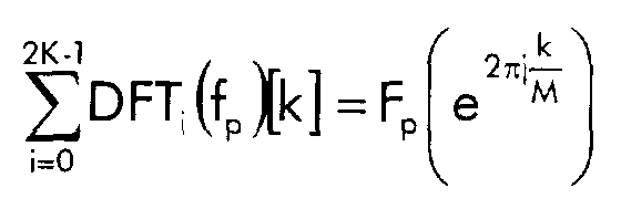
- M-1 if a time invariant signal is transmitted over the channel and analysed at the receiver side.
- the outputs of the demodulator DWMT DEMOD are combined to form quadrature amplitude modulated (QAM) symbols Q k .
- the DC and Nyquist components are calculated by the first two equations in expression (26).
- an M-points inverse Fourier Transform is performed on the channel transfer function to lead to the folded channel impulse response.
- DSL Digital Subscriber Line
- ADSL Asynchronous Digital Subscriber Line
- SDSL Serial Digital Subscriber Line
- HDSL High Speed Digital Subscriber Line
- VDSL Very High Speed Digital Subscriber Line
Landscapes
- Engineering & Computer Science (AREA)
- Signal Processing (AREA)
- Computer Networks & Wireless Communication (AREA)
- Power Engineering (AREA)
- Multimedia (AREA)
- Digital Transmission Methods That Use Modulated Carrier Waves (AREA)
- Circuits Of Receivers In General (AREA)
- Arrangements For Transmission Of Measured Signals (AREA)
- Reduction Or Emphasis Of Bandwidth Of Signals (AREA)
- Radar Systems Or Details Thereof (AREA)
- Cable Transmission Systems, Equalization Of Radio And Reduction Of Echo (AREA)
Abstract
Description


- ⊗ represents the convolution;
- I is an integer index;
- c(t) represents the channel impulse response; and
- gp,eq(t) represents the composite channel, defined as:











The outputs of the analysis filter banks are downsampled at the instant mM-1. The m-th output of the q-th branch of the analysis filter bank is then given by equation (14):












The assumption that the real low pass prototype h[n] is optimised by maximising its stopband attenuation, defined as the energy above the cut off frequency π / 2M, can be written mathematically as:


Claims (5)
- Method to determine samples of an estimated channel characteristic of a channel (CHANNEL) between a transmitter (TX) and a receiver (RX),
CHARACTERIZED IN THAT said method comprises the steps of:a. generating a predetermined periodic signal of transmit pulse amplitude modulated symbols;b. modulating waveforms with said transmit pulse amplitude modulated symbols in a cosine modulated filter bank (DWMT MOD) in said transmitter (TX);c. transferring said waveforms from said transmitter (TX) to said receiver (RX) over said channel (CHANNEL);d. demodulating received pulse amplitude modulated symbols from said waveforms in a cosine modulated filter bank (DWMT DEMOD) in said receiver (RX);e. combining pairs of said received pulse amplitude modulated symbols to form received quadrature amplitude modulated symbols; andf. dividing said received quadrature amplitude modulated symbols by said transmit pulse amplitude modulated symbols considered pairwise as transmit quadrature amplitude modulated symbols to thereby generate said samples of said estimated channel characteristic. - Method to determine samples of an estimated channel characteristic according to claim 1,
CHARACTERIZED IN THAT said method further comprises the step of:
g. inverse Fourier transforming said samples of said estimated channel characteristic. - Discrete wavelet multi tone transmitter (TX) comprising a cosine modulated filter bank (DWMT MOD) adapted to modulated waveforms with transmit pulse amplitude modulated symbols,
CHARACTERIZED IN THAT said discrete wavelet multi tone transmitter (TX) further comprises a pulse amplitude modulated symbol generator (PAM SYMBOL GENERATOR) whereto said cosine modulated filter bank (DWMT MOD) is cascade coupled, said pulse amplitude modulated symbol generator (PAM SYMBOL GENERATOR) being adapted to generate a predetermined periodic signal of transmit pulse amplitude modulated symbols and to apply said transmit pulse amplitude modulated symbols to said cosine modulated filter bank (DWMT MOD). - Discrete wavelet multi tone receiver (RX) comprising a cosine modulated filter bank (DWMT DEMOD) adapted to demodulate received pulse amplitude modulated symbols from waveforms,
CHARACTERIZED IN THAT said discrete wavelet multi tone receiver (RX) further comprises means to combine pairs of said received pulse amplitude modulated symbols to form received quadrature amplitude modulated symbols and means to divide said received quadrature amplitude modulated symbols by transmit pulse amplitude modulated symbols considered pairwise as transmit quadrature amplitude modulated symbols to thereby generate samples of an estimated channel characteristic of a channel (CHANNEL) between a transmitter (TX) and said discrete wavelet multi tone receiver (RX) whereover said transmit pulse amplitude modulated symbols are transferred. - Discrete wavelet multi tone receiver (RX) according to claim 4,
CHARACTERIZED IN THAT said discrete wavelet multi tone receiver (RX) further comprises an inverse Fourier transformer, adapted to inverse Fourier transform said samples of said estimated channel characteristic.
Priority Applications (9)
| Application Number | Priority Date | Filing Date | Title |
|---|---|---|---|
| EP00400620A EP1134945B1 (en) | 2000-03-07 | 2000-03-07 | Method to determine a channel characteristic and discrete wavelet receiver to perform the method |
| AT00400620T ATE395770T1 (en) | 2000-03-07 | 2000-03-07 | METHOD FOR DETERMINING A PROPERTY OF A CHANNEL AND DISCRETE WAVELET RECEIVER FOR IMPLEMENTING THE METHOD |
| DE60038868T DE60038868D1 (en) | 2000-03-07 | 2000-03-07 | Method for determining a property of a channel and discrete wavelet receiver for carrying out the method |
| IL14142501A IL141425A0 (en) | 2000-03-07 | 2001-02-14 | Method to determine a channel characteristic, and discrete wavelet transmitter and receiver to perform the method |
| AU21207/01A AU2120701A (en) | 2000-03-07 | 2001-02-14 | Method to determine a channel characteristic, and discrete wavelet transmitter and receiver to perform the method |
| JP2001041278A JP2001298439A (en) | 2000-03-07 | 2001-02-19 | Method for determining channel characteristics, and discrete wavelet transmitter and receiver implementing the method |
| CA002336556A CA2336556A1 (en) | 2000-03-07 | 2001-03-05 | Method to determine a channel characteristic, and discrete wavelet transmitter and receiver to perform the method |
| US09/799,129 US6952441B2 (en) | 2000-03-07 | 2001-03-06 | Method to determine a channel characteristic, and discrete wavelet transmitter and receiver to perform the method |
| KR1020010011705A KR20010088442A (en) | 2000-03-07 | 2001-03-07 | Method to determine a channel characteristic, and discrete wavelet transmitter and receiver to perform the method |
Applications Claiming Priority (1)
| Application Number | Priority Date | Filing Date | Title |
|---|---|---|---|
| EP00400620A EP1134945B1 (en) | 2000-03-07 | 2000-03-07 | Method to determine a channel characteristic and discrete wavelet receiver to perform the method |
Publications (2)
| Publication Number | Publication Date |
|---|---|
| EP1134945A1 true EP1134945A1 (en) | 2001-09-19 |
| EP1134945B1 EP1134945B1 (en) | 2008-05-14 |
Family
ID=8173587
Family Applications (1)
| Application Number | Title | Priority Date | Filing Date |
|---|---|---|---|
| EP00400620A Expired - Lifetime EP1134945B1 (en) | 2000-03-07 | 2000-03-07 | Method to determine a channel characteristic and discrete wavelet receiver to perform the method |
Country Status (9)
| Country | Link |
|---|---|
| US (1) | US6952441B2 (en) |
| EP (1) | EP1134945B1 (en) |
| JP (1) | JP2001298439A (en) |
| KR (1) | KR20010088442A (en) |
| AT (1) | ATE395770T1 (en) |
| AU (1) | AU2120701A (en) |
| CA (1) | CA2336556A1 (en) |
| DE (1) | DE60038868D1 (en) |
| IL (1) | IL141425A0 (en) |
Cited By (2)
| Publication number | Priority date | Publication date | Assignee | Title |
|---|---|---|---|---|
| FR2856535A1 (en) * | 2003-06-23 | 2004-12-24 | France Telecom | METHOD FOR MODULATING A DIGITAL SIGNAL AND MODULATOR FOR IMPLEMENTING THE METHOD |
| EP2827546A1 (en) * | 2013-07-19 | 2015-01-21 | BlackBerry Limited | Space and latency-efficient HSDPA receiver using a symbol de-interleaver |
Families Citing this family (26)
| Publication number | Priority date | Publication date | Assignee | Title |
|---|---|---|---|---|
| US7333535B2 (en) * | 2001-12-20 | 2008-02-19 | Texas Instruments Incorporated | Variable block rate ADSL |
| ES2550821T3 (en) | 2002-01-24 | 2015-11-12 | Panasonic Corporation | Method and system for carrier communications by power line |
| KR100813251B1 (en) * | 2002-03-06 | 2008-03-13 | 삼성전자주식회사 | Alignment system of ferroelectric liquid crystal panel and alignment method using the same |
| US7627056B1 (en) | 2002-03-29 | 2009-12-01 | Scientific Research Corporation | System and method for orthogonally multiplexed signal transmission and reception on a non-contiguous spectral basis |
| US7206359B2 (en) * | 2002-03-29 | 2007-04-17 | Scientific Research Corporation | System and method for orthogonally multiplexed signal transmission and reception |
| US7164724B2 (en) * | 2002-09-25 | 2007-01-16 | Matsushita Electric Industrial Co., Ltd. | Communication apparatus |
| JP4161693B2 (en) * | 2002-11-25 | 2008-10-08 | 松下電器産業株式会社 | Multicarrier transmission apparatus, multicarrier reception apparatus, and multicarrier communication apparatus |
| JP4658042B2 (en) | 2003-06-18 | 2011-03-23 | パナソニック株式会社 | Method and apparatus for receiving digital multi-carrier signals using wavelet transform |
| WO2005004426A1 (en) * | 2003-07-03 | 2005-01-13 | Matsushita Electric Industrial Co., Ltd. | Transmitter and method for digital multi-carrier transmission using wavelets |
| JP4356392B2 (en) | 2003-08-07 | 2009-11-04 | パナソニック株式会社 | Communication device |
| US7639596B2 (en) * | 2003-12-07 | 2009-12-29 | Adaptive Spectrum And Signal Alignment, Inc. | High speed multiple loop DSL system |
| US8115605B2 (en) * | 2003-12-23 | 2012-02-14 | Stmicroelectronics, Inc. | Power line communications device in which physical communications protocol layer operation is dynamically selectable |
| JP2005311413A (en) * | 2004-04-16 | 2005-11-04 | Matsushita Electric Ind Co Ltd | Communication apparatus and communication method |
| JP4637498B2 (en) | 2004-04-16 | 2011-02-23 | パナソニック株式会社 | Communication apparatus and communication method |
| GB0412215D0 (en) * | 2004-06-02 | 2004-07-07 | Aea Technology Plc | Processing of railway track data |
| JP5052742B2 (en) * | 2004-07-22 | 2012-10-17 | パナソニック株式会社 | Transmitting apparatus and communication system using the same |
| JP4606149B2 (en) | 2004-12-16 | 2011-01-05 | パナソニック株式会社 | Receiving apparatus and receiving method |
| JP4699113B2 (en) * | 2005-07-05 | 2011-06-08 | パナソニック株式会社 | Multi-carrier communication apparatus and multi-carrier communication method |
| JP4749815B2 (en) * | 2005-09-27 | 2011-08-17 | パナソニック株式会社 | Multi-carrier communication apparatus, multi-carrier communication system, and multi-carrier communication method |
| DE602005010592D1 (en) * | 2005-11-15 | 2008-12-04 | Alcatel Lucent | Method for transmitting channel quality information in a multi-carrier radio communication system and corresponding mobile station and base station |
| US20070165730A1 (en) * | 2006-01-17 | 2007-07-19 | Motorola, Inc. | Transmitter cellular communication system and method of transmitting therefor |
| JP4548427B2 (en) * | 2007-01-26 | 2010-09-22 | パナソニック株式会社 | Power line carrier communication equipment |
| US8358575B2 (en) * | 2007-11-12 | 2013-01-22 | Analog Devices, Inc. | Methods and apparatus for generating and processing transmitter signals |
| GB2463508B (en) * | 2008-09-16 | 2011-04-13 | Toshiba Res Europ Ltd | Wireless communications apparatus |
| JP5340199B2 (en) * | 2010-02-18 | 2013-11-13 | 日本放送協会 | Multi-carrier modulation apparatus and demodulation apparatus |
| KR101746799B1 (en) * | 2015-11-04 | 2017-06-14 | 주식회사 쏠리드 | distributed antenna system |
Family Cites Families (6)
| Publication number | Priority date | Publication date | Assignee | Title |
|---|---|---|---|---|
| US5005189A (en) * | 1989-01-23 | 1991-04-02 | Hackett Jr Charles M | Detection of digital signals received from multipath channels |
| US5436940A (en) * | 1992-06-11 | 1995-07-25 | Massachusetts Institute Of Technology | Quadrature mirror filter banks and method |
| US5715280A (en) * | 1996-06-20 | 1998-02-03 | Aware, Inc. | Method for partially modulating and demodulating data in a multi-carrier transmission system |
| US6101223A (en) * | 1997-03-06 | 2000-08-08 | Paradyne Corporation | System and method for optimizing the uncoded modulation of circular constellations using circular precoding and nonlinear encoding |
| US6075814A (en) * | 1997-05-09 | 2000-06-13 | Broadcom Homenetworking, Inc. | Method and apparatus for reducing signal processing requirements for transmitting packet-based data with a modem |
| US6590893B1 (en) * | 1999-04-07 | 2003-07-08 | Legerity, Inc. | Adaptive transmission system in a network |
-
2000
- 2000-03-07 DE DE60038868T patent/DE60038868D1/en not_active Expired - Lifetime
- 2000-03-07 AT AT00400620T patent/ATE395770T1/en not_active IP Right Cessation
- 2000-03-07 EP EP00400620A patent/EP1134945B1/en not_active Expired - Lifetime
-
2001
- 2001-02-14 IL IL14142501A patent/IL141425A0/en unknown
- 2001-02-14 AU AU21207/01A patent/AU2120701A/en not_active Abandoned
- 2001-02-19 JP JP2001041278A patent/JP2001298439A/en not_active Withdrawn
- 2001-03-05 CA CA002336556A patent/CA2336556A1/en not_active Abandoned
- 2001-03-06 US US09/799,129 patent/US6952441B2/en not_active Expired - Lifetime
- 2001-03-07 KR KR1020010011705A patent/KR20010088442A/en not_active Withdrawn
Non-Patent Citations (3)
| Title |
|---|
| GOVARDHANAGIRI S ET AL: "Performance analysis of multicarrier modulation systems using cosine modulated filter banks", 1999 IEEE INTERNATIONAL CONFERENCE ON ACOUSTICS, SPEECH, AND SIGNAL PROCESSING, vol. 3, 15 March 1999 (1999-03-15) - 19 March 1999 (1999-03-19), Piscataway, NJ, USA, IEEE, USA, pages 1405 - 1408, XP002139688, ISBN: 0-7803-5041-3 * |
| GROSS R ET AL: "DISCRETE WAVELET MULTITONE (DWMT) SYSTEM FOR DIGITAL TRANSMISSION OVER HFC LINKS", PROCEEDINGS OF THE SPIE, 23 October 1995 (1995-10-23), XP000576748 * |
| SANDBERG S D ET AL: "OVERLAPPED DISCRETE MULTITONE MODULATION FOR HIGH SPEED COPPER WIRE COMMUNICATIONS", IEEE JOURNAL ON SELECTED AREAS IN COMMUNICATIONS, vol. 13, no. 9, 1 December 1995 (1995-12-01), US, NEW YORK, NY, pages 1571 - 1585, XP000543156, ISSN: 0733-8716 * |
Cited By (4)
| Publication number | Priority date | Publication date | Assignee | Title |
|---|---|---|---|---|
| FR2856535A1 (en) * | 2003-06-23 | 2004-12-24 | France Telecom | METHOD FOR MODULATING A DIGITAL SIGNAL AND MODULATOR FOR IMPLEMENTING THE METHOD |
| WO2005004425A1 (en) * | 2003-06-23 | 2005-01-13 | France Telecom | Method and apparatus for the wavelet transform modulation of a digital signal |
| EP2827546A1 (en) * | 2013-07-19 | 2015-01-21 | BlackBerry Limited | Space and latency-efficient HSDPA receiver using a symbol de-interleaver |
| US9509545B2 (en) | 2013-07-19 | 2016-11-29 | Blackberry Limited | Space and latency-efficient HSDPA receiver using a symbol de-interleaver |
Also Published As
| Publication number | Publication date |
|---|---|
| EP1134945B1 (en) | 2008-05-14 |
| US6952441B2 (en) | 2005-10-04 |
| JP2001298439A (en) | 2001-10-26 |
| ATE395770T1 (en) | 2008-05-15 |
| US20010033612A1 (en) | 2001-10-25 |
| DE60038868D1 (en) | 2008-06-26 |
| IL141425A0 (en) | 2002-03-10 |
| KR20010088442A (en) | 2001-09-26 |
| AU2120701A (en) | 2001-09-13 |
| CA2336556A1 (en) | 2001-09-07 |
Similar Documents
| Publication | Publication Date | Title |
|---|---|---|
| US6952441B2 (en) | Method to determine a channel characteristic, and discrete wavelet transmitter and receiver to perform the method | |
| Renfors et al. | Analysis and design of efficient and flexible fast-convolution based multirate filter banks | |
| AU733587B2 (en) | Method and apparatus for sub-band modulation of signals for transmission and/or storage | |
| US5317596A (en) | Method and apparatus for echo cancellation with discrete multitone modulation | |
| US5631610A (en) | Single side-band modulation system for use in digitally implemented multicarrier transmission systems | |
| JP3848421B2 (en) | Multiplexing apparatus and multiplexing system for discrete-time signal, and multiplexing method for discrete-time signal | |
| US6718019B1 (en) | Method and apparatus for wireline characterization | |
| JP2006512841A (en) | Method and apparatus for signal processing using filter bank | |
| CN100593309C (en) | Wavelet multi-carrier communication device | |
| JP2003536325A (en) | System and method for a multi-carrier transceiver with radio frequency interference reduction | |
| US6985521B1 (en) | Method and apparatus for channel estimation for X-DSL communications | |
| US7443917B2 (en) | Method and system for transmission of information data over a communication line | |
| US20010032225A1 (en) | Method of frequency domain filtering employing a real to analytic transform | |
| JP4680459B2 (en) | Method for transmitting an offset modulated (BFDM / OM) multi-carrier signal | |
| US7477683B2 (en) | Periodic DMT signals with cyclic extension | |
| WO1995017046A1 (en) | An improved discrete multitone echo canceler | |
| GB2366494A (en) | Dividing bandwidth into sub-bands prior to implementing an FFT in a high data rate communications network | |
| JP4841713B2 (en) | DSL transmission system with echo canceller | |
| Cruz-Roldán et al. | Design of multi-channel near-perfect-reconstruction transmultiplexers using cosine-modulated filter banks | |
| US6873650B1 (en) | Transmission rate compensation for a digital multi-tone transceiver | |
| EP1232569B1 (en) | Method and apparatus for characterization of disturbers in communication systems | |
| Martin-Martin et al. | Optimized transmultiplexers for multirate systems | |
| CN1135777C (en) | Digital system for subscriber lines allowing high bit rates | |
| Sablatash | Designs and architectures of filter bank trees for spectrally efficient multi-user communications: review, modifications and extensions of wavelet packet filter bank trees | |
| Turcza et al. | Circular real sine/cosine Gabor transform modulator for Power Line Communication |
Legal Events
| Date | Code | Title | Description |
|---|---|---|---|
| PUAI | Public reference made under article 153(3) epc to a published international application that has entered the european phase |
Free format text: ORIGINAL CODE: 0009012 |
|
| AK | Designated contracting states |
Kind code of ref document: A1 Designated state(s): AT BE CH CY DE DK ES FI FR GB GR IE IT LI LU MC NL PT SE |
|
| AX | Request for extension of the european patent |
Free format text: AL;LT;LV;MK;RO;SI |
|
| 17P | Request for examination filed |
Effective date: 20020319 |
|
| AKX | Designation fees paid |
Free format text: AT BE CH CY DE DK ES FI FR GB GR IE IT LI LU MC NL PT SE |
|
| 17Q | First examination report despatched |
Effective date: 20060802 |
|
| RAP1 | Party data changed (applicant data changed or rights of an application transferred) |
Owner name: ALCATEL LUCENT |
|
| GRAP | Despatch of communication of intention to grant a patent |
Free format text: ORIGINAL CODE: EPIDOSNIGR1 |
|
| RIC1 | Information provided on ipc code assigned before grant |
Ipc: H04L 27/26 20060101ALN20070709BHEP Ipc: H04L 25/49 20060101ALN20070709BHEP Ipc: H04L 25/02 20060101AFI20070709BHEP |
|
| RTI1 | Title (correction) |
Free format text: METHOD TO DETERMINE A CHANNEL CHARACTERISTIC AND DISCRETE WAVELET RECEIVER TO PERFORM THE METHOD |
|
| GRAS | Grant fee paid |
Free format text: ORIGINAL CODE: EPIDOSNIGR3 |
|
| GRAA | (expected) grant |
Free format text: ORIGINAL CODE: 0009210 |
|
| AK | Designated contracting states |
Kind code of ref document: B1 Designated state(s): AT BE CH CY DE DK ES FI FR GB GR IE IT LI LU MC NL PT SE |
|
| REG | Reference to a national code |
Ref country code: GB Ref legal event code: FG4D |
|
| REG | Reference to a national code |
Ref country code: CH Ref legal event code: EP |
|
| REG | Reference to a national code |
Ref country code: IE Ref legal event code: FG4D Free format text: LANGUAGE OF EP DOCUMENT: FRENCH |
|
| REF | Corresponds to: |
Ref document number: 60038868 Country of ref document: DE Date of ref document: 20080626 Kind code of ref document: P |
|
| PG25 | Lapsed in a contracting state [announced via postgrant information from national office to epo] |
Ref country code: ES Free format text: LAPSE BECAUSE OF FAILURE TO SUBMIT A TRANSLATION OF THE DESCRIPTION OR TO PAY THE FEE WITHIN THE PRESCRIBED TIME-LIMIT Effective date: 20080825 Ref country code: FI Free format text: LAPSE BECAUSE OF FAILURE TO SUBMIT A TRANSLATION OF THE DESCRIPTION OR TO PAY THE FEE WITHIN THE PRESCRIBED TIME-LIMIT Effective date: 20080514 |
|
| NLV1 | Nl: lapsed or annulled due to failure to fulfill the requirements of art. 29p and 29m of the patents act | ||
| PG25 | Lapsed in a contracting state [announced via postgrant information from national office to epo] |
Ref country code: AT Free format text: LAPSE BECAUSE OF FAILURE TO SUBMIT A TRANSLATION OF THE DESCRIPTION OR TO PAY THE FEE WITHIN THE PRESCRIBED TIME-LIMIT Effective date: 20080514 Ref country code: NL Free format text: LAPSE BECAUSE OF FAILURE TO SUBMIT A TRANSLATION OF THE DESCRIPTION OR TO PAY THE FEE WITHIN THE PRESCRIBED TIME-LIMIT Effective date: 20080514 |
|
| PG25 | Lapsed in a contracting state [announced via postgrant information from national office to epo] |
Ref country code: DK Free format text: LAPSE BECAUSE OF FAILURE TO SUBMIT A TRANSLATION OF THE DESCRIPTION OR TO PAY THE FEE WITHIN THE PRESCRIBED TIME-LIMIT Effective date: 20080514 Ref country code: PT Free format text: LAPSE BECAUSE OF FAILURE TO SUBMIT A TRANSLATION OF THE DESCRIPTION OR TO PAY THE FEE WITHIN THE PRESCRIBED TIME-LIMIT Effective date: 20081014 Ref country code: SE Free format text: LAPSE BECAUSE OF FAILURE TO SUBMIT A TRANSLATION OF THE DESCRIPTION OR TO PAY THE FEE WITHIN THE PRESCRIBED TIME-LIMIT Effective date: 20080814 |
|
| PG25 | Lapsed in a contracting state [announced via postgrant information from national office to epo] |
Ref country code: BE Free format text: LAPSE BECAUSE OF FAILURE TO SUBMIT A TRANSLATION OF THE DESCRIPTION OR TO PAY THE FEE WITHIN THE PRESCRIBED TIME-LIMIT Effective date: 20080514 |
|
| PLBE | No opposition filed within time limit |
Free format text: ORIGINAL CODE: 0009261 |
|
| STAA | Information on the status of an ep patent application or granted ep patent |
Free format text: STATUS: NO OPPOSITION FILED WITHIN TIME LIMIT |
|
| 26N | No opposition filed |
Effective date: 20090217 |
|
| PG25 | Lapsed in a contracting state [announced via postgrant information from national office to epo] |
Ref country code: IT Free format text: LAPSE BECAUSE OF FAILURE TO SUBMIT A TRANSLATION OF THE DESCRIPTION OR TO PAY THE FEE WITHIN THE PRESCRIBED TIME-LIMIT Effective date: 20080514 |
|
| PG25 | Lapsed in a contracting state [announced via postgrant information from national office to epo] |
Ref country code: MC Free format text: LAPSE BECAUSE OF NON-PAYMENT OF DUE FEES Effective date: 20090331 |
|
| REG | Reference to a national code |
Ref country code: CH Ref legal event code: PL |
|
| PG25 | Lapsed in a contracting state [announced via postgrant information from national office to epo] |
Ref country code: IE Free format text: LAPSE BECAUSE OF NON-PAYMENT OF DUE FEES Effective date: 20090307 Ref country code: CH Free format text: LAPSE BECAUSE OF NON-PAYMENT OF DUE FEES Effective date: 20090331 Ref country code: LI Free format text: LAPSE BECAUSE OF NON-PAYMENT OF DUE FEES Effective date: 20090331 |
|
| PG25 | Lapsed in a contracting state [announced via postgrant information from national office to epo] |
Ref country code: GR Free format text: LAPSE BECAUSE OF FAILURE TO SUBMIT A TRANSLATION OF THE DESCRIPTION OR TO PAY THE FEE WITHIN THE PRESCRIBED TIME-LIMIT Effective date: 20080815 |
|
| PG25 | Lapsed in a contracting state [announced via postgrant information from national office to epo] |
Ref country code: LU Free format text: LAPSE BECAUSE OF NON-PAYMENT OF DUE FEES Effective date: 20090307 |
|
| PG25 | Lapsed in a contracting state [announced via postgrant information from national office to epo] |
Ref country code: CY Free format text: LAPSE BECAUSE OF FAILURE TO SUBMIT A TRANSLATION OF THE DESCRIPTION OR TO PAY THE FEE WITHIN THE PRESCRIBED TIME-LIMIT Effective date: 20080514 |
|
| REG | Reference to a national code |
Ref country code: FR Ref legal event code: GC Effective date: 20131018 |
|
| REG | Reference to a national code |
Ref country code: FR Ref legal event code: RG Effective date: 20141016 |
|
| REG | Reference to a national code |
Ref country code: FR Ref legal event code: PLFP Year of fee payment: 16 |
|
| REG | Reference to a national code |
Ref country code: FR Ref legal event code: CA Effective date: 20150521 |
|
| REG | Reference to a national code |
Ref country code: FR Ref legal event code: CA Effective date: 20150521 |
|
| REG | Reference to a national code |
Ref country code: FR Ref legal event code: PLFP Year of fee payment: 17 |
|
| REG | Reference to a national code |
Ref country code: FR Ref legal event code: PLFP Year of fee payment: 18 |
|
| PGFP | Annual fee paid to national office [announced via postgrant information from national office to epo] |
Ref country code: DE Payment date: 20170322 Year of fee payment: 18 Ref country code: FR Payment date: 20170322 Year of fee payment: 18 |
|
| PGFP | Annual fee paid to national office [announced via postgrant information from national office to epo] |
Ref country code: GB Payment date: 20170322 Year of fee payment: 18 |
|
| REG | Reference to a national code |
Ref country code: DE Ref legal event code: R119 Ref document number: 60038868 Country of ref document: DE |
|
| GBPC | Gb: european patent ceased through non-payment of renewal fee |
Effective date: 20180307 |
|
| PG25 | Lapsed in a contracting state [announced via postgrant information from national office to epo] |
Ref country code: DE Free format text: LAPSE BECAUSE OF NON-PAYMENT OF DUE FEES Effective date: 20181002 |
|
| PG25 | Lapsed in a contracting state [announced via postgrant information from national office to epo] |
Ref country code: GB Free format text: LAPSE BECAUSE OF NON-PAYMENT OF DUE FEES Effective date: 20180307 |
|
| PG25 | Lapsed in a contracting state [announced via postgrant information from national office to epo] |
Ref country code: FR Free format text: LAPSE BECAUSE OF NON-PAYMENT OF DUE FEES Effective date: 20180331 |