EP1134853A1 - Entertainment device having operation device types detecting function, operating device, and entertainment device main body - Google Patents
Entertainment device having operation device types detecting function, operating device, and entertainment device main body Download PDFInfo
- Publication number
- EP1134853A1 EP1134853A1 EP00957092A EP00957092A EP1134853A1 EP 1134853 A1 EP1134853 A1 EP 1134853A1 EP 00957092 A EP00957092 A EP 00957092A EP 00957092 A EP00957092 A EP 00957092A EP 1134853 A1 EP1134853 A1 EP 1134853A1
- Authority
- EP
- European Patent Office
- Prior art keywords
- operation device
- potential
- connector
- metal
- machine body
- Prior art date
- Legal status (The legal status is an assumption and is not a legal conclusion. Google has not performed a legal analysis and makes no representation as to the accuracy of the status listed.)
- Withdrawn
Links
- 239000002184 metal Substances 0.000 claims abstract description 85
- 230000002093 peripheral effect Effects 0.000 claims abstract description 4
- 238000004891 communication Methods 0.000 claims description 24
- 238000000034 method Methods 0.000 claims description 11
- 238000001514 detection method Methods 0.000 claims 1
- 230000003287 optical effect Effects 0.000 description 11
- 238000010586 diagram Methods 0.000 description 3
- 238000010276 construction Methods 0.000 description 1
- 230000001172 regenerating effect Effects 0.000 description 1
- 230000000717 retained effect Effects 0.000 description 1
Images



Classifications
-
- H—ELECTRICITY
- H01—ELECTRIC ELEMENTS
- H01R—ELECTRICALLY-CONDUCTIVE CONNECTIONS; STRUCTURAL ASSOCIATIONS OF A PLURALITY OF MUTUALLY-INSULATED ELECTRICAL CONNECTING ELEMENTS; COUPLING DEVICES; CURRENT COLLECTORS
- H01R13/00—Details of coupling devices of the kinds covered by groups H01R12/70 or H01R24/00 - H01R33/00
- H01R13/64—Means for preventing incorrect coupling
-
- H—ELECTRICITY
- H01—ELECTRIC ELEMENTS
- H01R—ELECTRICALLY-CONDUCTIVE CONNECTIONS; STRUCTURAL ASSOCIATIONS OF A PLURALITY OF MUTUALLY-INSULATED ELECTRICAL CONNECTING ELEMENTS; COUPLING DEVICES; CURRENT COLLECTORS
- H01R13/00—Details of coupling devices of the kinds covered by groups H01R12/70 or H01R24/00 - H01R33/00
- H01R13/66—Structural association with built-in electrical component
- H01R13/70—Structural association with built-in electrical component with built-in switch
- H01R13/703—Structural association with built-in electrical component with built-in switch operated by engagement or disengagement of coupling parts, e.g. dual-continuity coupling part
- H01R13/7039—Structural association with built-in electrical component with built-in switch operated by engagement or disengagement of coupling parts, e.g. dual-continuity coupling part the coupling part with coding means activating the switch to establish different circuits
-
- H—ELECTRICITY
- H01—ELECTRIC ELEMENTS
- H01R—ELECTRICALLY-CONDUCTIVE CONNECTIONS; STRUCTURAL ASSOCIATIONS OF A PLURALITY OF MUTUALLY-INSULATED ELECTRICAL CONNECTING ELEMENTS; COUPLING DEVICES; CURRENT COLLECTORS
- H01R29/00—Coupling parts for selective co-operation with a counterpart in different ways to establish different circuits, e.g. for voltage selection, for series-parallel selection, programmable connectors
-
- Y—GENERAL TAGGING OF NEW TECHNOLOGICAL DEVELOPMENTS; GENERAL TAGGING OF CROSS-SECTIONAL TECHNOLOGIES SPANNING OVER SEVERAL SECTIONS OF THE IPC; TECHNICAL SUBJECTS COVERED BY FORMER USPC CROSS-REFERENCE ART COLLECTIONS [XRACs] AND DIGESTS
- Y10—TECHNICAL SUBJECTS COVERED BY FORMER USPC
- Y10S—TECHNICAL SUBJECTS COVERED BY FORMER USPC CROSS-REFERENCE ART COLLECTIONS [XRACs] AND DIGESTS
- Y10S439/00—Electrical connectors
- Y10S439/956—Electrical connectors with means to allow selection of diverse voltage or polarity
Definitions
- the present invention relates to an entertainment system using a operation device connected thereto.
- the entertainment system comprises, as shown in Fig. 1, a machine body 10 having an optical disk reproducing section 1, and an operation device 20 for accepting the user's operations connected thereto.
- a processing unit within the machine body 10 receives a game program and image information etc. recorded in the optical disc from the optical disk reproducing section 1 and displays the image on the external display.
- the processing unit communicates with the operation device 20, to accept contents of the user's oprations, executes a game program according to the accepted user's controls, and changes the display images etc.
- the operation device 20 comprises a operation body 22 having switches 24-29 arranged thereon for receiving the user's operations, a cable 23, and a connector 21.
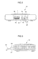
- the operation unit 20 is connected with respect to each other by inserting the connector 21 into the connecting portions 4a and 4b of the machine body 10 as shown in Fig. 1, Fig. 2, and Fig. 3.
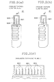
- the connector 21 comprises nine pins 601 therein as shown in Figs 5(a), 5(b), and 5(c).
- the retaining portions 502, 503, and 504 are recesses to engage with the metal projection provided within the connecting portions 4a and 4b.
- a grounding metal 505 is inserted on the bottom surface of the recess of the retaining portion 503 located in the center, and is exposed from the bottom surface of the retaining portion 503.
- the grounding metal 505 is supplied with a ground potential when it comes into contact with the metal projection at the ground potential provided on the machine body 10 to be engaged therewith. Therefore, the retaining portion 503 located in the center serves not only as a retaining portion, but also as a grounding terminal.
- the machine body 10 is also provided with receiving portions 3a, 3b for a card-type external memory device 30 to be mounted thereon, and switches 11, 12.
- the development of the operation device 20 has been pursued to produce a new model by making improvement to the operation device 20 described above, for example, by increasing the number of operations that are accepted by the switches 24-29 of the operation device body 22, or by increasing communication speed between the operation device 20 and the machine body 10.
- the connector of the operation device for the new model should have the same configuration as that of the connector of the conventional operation device 20.
- the machine body cannot support all the communication modes for each model, unless the machine body can discriminate whether the connected operation device is the conventional model or the new model.
- a pin is added to the new model for discriminating the new model from the conventional one.
- adding such a pin to the operation device of the new model changes the configuration of the connector, whereby the compatibility cannot be established.
- an entertainment system comprising an operation device having a connector, and a machine body having a connecting portion to be connected to said connector wherein:
- the entertainment system 200 of this embodiment is a series of models, which are systematized members of the entertainment system 100 shown in Fig.1.
- the entertainment system 200 of this embodiment comprises, as shown in Fig. 6 and Fig. 7, a machine body 210 and an operation device 220 detachably connected to the machine body 210.
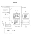
- the machine body 210 comprises, as in Fig. 7, the optical disk reproducing portion 1, an arithmetic processing unit 2, card-type exterior memory device receiving portions 3a and 3b, operation device connecting portions 204a and 204b, a switch 11, and a display connecting portion 5.
- the operation device 220 is a device for accepting the user's operations, one or two of which can be connected to the connecting portions 204a and 204b of the machine body 210.
- the operation device 220 comprises an operation device body 222 having a press down type switches 224-229, and lever-type switches 218 and 219 for accepting the user's operations, a cable 223, and a connector 221.
- the machine body 210 and the operation device 220 are connected by inserting the connector 221 into the connecting portions 204a and 204b of the machine body 210.
- the operation device 220 is a high performance device wherein the switches 218, 219, 224-229 are capable of accepting a larger number of types of oprations than the conventional operation device 20.
- the communication speed between the operation device 220 and the machine body 210 is higher than that between the conventional operation device 20 and the machine body 10, and the communication procedure is also different.
- the arithmetic processing unit 2 of the machine body 210 has a capability of communicating in a communicating procedure that is adapted to the operation device 20 and in a communicating procedure that is adapted to the operation device 220.
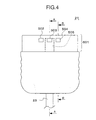
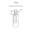
- the connector 221 of the operation device 220 has the same profile as the conventional connector 21 shown in Fig. 4, Figs. 5(a), 5(b), and 5(c), and the number of the pins 601 provided therein and the spacing between adjacent pins are the same as the conventional connector.
- the upper surface of an inserting portion 501 of the connector 221 is provided with retaining portions 802, 803, and 804 of the same configuration and at the same position as retaining portions 502, 503, and 504 of the conventional connector 21.
- the connector 221 of this embodiment differs from the conventional connector 21 in that the width of the grounding metal 805 is wider, and in that the grounding metal 805 is inserted not only to the bottom surface of the central retaining portion 803, but also to the bottom surface of the retaining portion 802. Therefore, the grounding metal 805 is exposed on the bottom surfaces of the retaining portions 802 and 803.
- the recess of the retaining portion 802 has an elongated configuration toward the tip of the inserting portion 501, and the grounding metal 805 is exposed on the retaining portion 802 until the vicinity of the tip.
- the grounding metal 805 is connected to the electromagnetic shielding (not shown) within the connector 221.
- the grounding metal 805 in itself serves as an electromagnetic shield for the inserting portion 501.
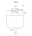
- the front face of the machine body 210 is provided with connecting portions 204a and 204b for connecting the connector 221 of the operation device 220.
- the connector 21 of the conventional operation device 20 can be connected to the connecting portions 204a and 204b of the machine body.
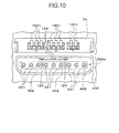
- the connecting portion 204a is, as shown in Fig. 10 and Fig. 11, provided with three bases 402 within the opening 400, and nine cylindrical terminals 401 are arranged in the bases 402.
- the cylindrical terminal 401 is connected to the nine pins 601 of the connector 21, 221.
- metal plates 121, 122 of the shape as shown in Fig. 12 arranged without contact with respect to each other.
- the metal plate 121 is formed with lever shaped projections 124, 125 at two points, while the metal plate 122 is formed with a lever shaped projection 123 at one point. These projections 123, 124, and 125 are protrude inward the opening 400 in a line as shown in Fig. 10.
- the central projection 124 is divided into two pieces in order to provide two contact points.
- the metal plate 121 is electrically connected to the ground cable within the machine body 210.
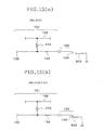
- the metal plate 122 is connected to a pull-up circuit 131 as shown in Fig. 13(a).
- the pull-up circuit 131 comprises wiring 134 connected to the metal plate 122, a signal line 132 at a signal potential, and a resistance 133 connecting the signal line 132 at a signal potential and the wiring 134. Therefore, when the metal plate 122 is in an open state where it is not in contact with other signal lines as shown in Fig. 13(a), the wiring 134 will be equal to the signal potential of the signal line 132, thus pulling up the potential of the signal line 132 to the signal potential.
- the processing unit 2 has a function to determine whether the potential of the terminal 135 is at the signal potential or at the ground potential by executing a program within the inner memory device at predetermined time intervals.
- connecting portion 204b Since the structure of the connecting portion 204b is the same as that of the connecting portion 204a, description about the connecting portion 204b will not be made here.
- the inserting portion 501 of the connector 221 is fitted in a clearance between the opening 400 of the connecting portion 204a and the base 402. Accordingly, the projections 123, 124, and 125 are engaged with the retaining portions 802, 803, and 804 provided on the upper surface of the connector 221 respectively, so that the connector 221 is locked to the connecting portion 204a.
- the nine pins 601 of the connector 221 are connected with the nine cylindrical terminals 401 in the base 402.
- the retaining portion 802 is formed until the vicinity of the tip of the inserting portion 501, so that the projection 123 of the metal plate 122 is electrically connected to the grounding metal 805 exposed on the bottom surface of the retaining portion 802 when the connector 221 is inserted. At this point of time, since the potential of the grounding metal 802 is not fallen down to the ground level, the signal line 134 of the pull-up circuit 131 is still at a signal potential. When the connector 221 is inserted deeper, the projection 124 comes into contact with the grounding metal 805 on the bottom surface of the retaining portion 803 electrically, whereby the potential of the grounding metal 805 and thus of the metal plate 122 connected to the grounding metal 805 fall down to a ground level, as shown in Fig.
- the signal line 134 of the pull-up circuit 131 changes from the signal potential to the ground potential.
- the processing unit 2 determines that the potential of the terminal 135 of the signal line 134 is fallen down to the ground level, thereby detecting that the connected operation device is the operation device 220. Therefore, the processing unit 2 can conduct communications in the communication procedure adapted to the operation device 220, and receive operation information from the operation device 220 via the pins 601 and the terminals 401.
- the potential of the electromagnetic shield connected to the grounding metal 805 falls down to the ground level as well, thereby functioning as an electromagnetic shield.
- the grounding metal 805 in itself prevents electromagnetic waves from leaking through the inserting portion 501, and serves as a part of an electromagnetic shield.
- the inserting portion 501 of the connector 21 is fitted in a clearance between the opening 400 of the connecting portion 204a and the base 402, so that the nine pins 601 of the connector 221 can be connected to the nine cylindrical terminals 401 of the base 402.
- the projections 123, 124, and 125 of the connecting portion 204a engage with the retaining portions 502, 503, and 504 of the conventional connector 21 and the connector 221 is retained in the connecting portion 204a.
- the grounding metal 505 exposed on the bottom surface of the central retaining portion 503 comes into electrical contact with the projection 124 of the metal plate 121 at the ground potential, the potential of the grounding metal 505 falls down to the ground level. Accordingly, the potential of the electromagnetic shield connected to the grounding metal 505 falls to the ground level as well, thereby serving as an electromagnetic shield.
- the grounding metal 505 in itself serves as an electromagnetic shield that shields the connector 21.
- the projection 123 connected to the pull-up circuit 131 is engaged with the retaining portion 502 only mechanically because the grounding metal 505 is not exposed on the bottom surface of the retaining portion 502, whereby it cannot be connected to the grounding metal 505 electrically. Therefore, the signal line 134 of the pull-up circuit 131 remains at the signal potential.
- the processing unit 2 determines that the terminal 135 of the signal line 134 is still at the signal potential, thereby detecting that the connected operation device is the operation device 20. Then the processing unit 2 can conduct communications in the communication mode adapted to the operation device 20 and receive opration information from the operation device 20 via the pins 601 and the terminals 401.
- the configuration of the connector 221 is the same as the conventional connector 21, but the grounding metal 805 is exposed from a plurality of retaining portions 802 and 803. Therefore, whether the model of the connected operation device is the operation device 220 or the conventional operation device 20 can be determined depending on whether the machine body 210 can detect the ground potential at one of the exposed portion of the grounding metal 805 or not. In this way, since the operation device 220 is improved only in that the number of the locations of the grounding metal 805 exposed is increased, and thus the number of the terminals 601 is not increased, the configuration of the connector 221 may be maintained as in the conventional connector 21, thereby ensuring compatibility between the operation device 20 and the operation device 220.
- the machine body 210 can detect the model of the connected operation device by the metal plate 122 and the pull-up circuit 131, whereby communications can be conducted in the communication mode that is adapted to the performance of the operation device. Since the pull-up circuit 131 and the metal plate 122 are simple in construction, it can be arranged in the machine body 210 easily at low cost.
- the optical disk reproducing section 1 of the machine body 210 comprises a disk tray 201a, a switch 1b, an axis of rotation, a rotary drive, a playback head, and a reproducing circuit.
- the disk tray 201a is, as shown in Fig. 6, arranged on the front face of the machine body 210, and ejected toward the front by pressing the switch 1b.
- the rotary drive rotates the axis of rotation to allow the playback head to read information recorded therein.
- the switch 1b is a switch to withdraw the disk tray 201a.
- the reset switch 11 is also provided on the front face of the machine body 210.
- receiving portions 3a and 3b for mounting a card-type external memory device 30, as shown in Fig. 6.
- the receiving portions 3a and 3b are provided with terminals 1501 as shown in Fig. 10 and Fig. 11.
- the terminals 1501 are brought into contact with a connecting terminal on the mounted card-type external memory device 30.
- a shutter 1402 At the entrance of the receiving portion 3a, 3b, there is provided a shutter 1402 that is closed by a force of the spring 1403 when the card-type external memory device 30 is not mounted.
- the user connects the external display 40 to the connecting portion 5 of the machine body 210, and the operation device 20 or 220 to the connecting portions 204a and 204b, when the user plays game by the entertainment system 200. Then the user turns the power source switch, not shown, ON, places an optical disk on the disk tray 201 of the optical disk reproducing section 1 to load it. Then the processing unit 2 of the machine body 210 receives the game program or image information etc. recorded on the optical disk from the optical disk regenerating section 1 and displays it on the external display 40.
- the processing unit 2 detects whether the connected operation device is the operation device 20 or the operation device 220 by determining whether the potential of the terminal 135 of the pull-up circuit 131 is at the signal potential or at the ground potential as described above, and then conducts communications with the operation device in the communication mode adapted to the model of the detected operation device to receive contents of the user's operations.
- the processing unit 2 changes the displaying image by executing a game program according to the received contents of the operations.
- the processing unit 2 communicates with the card-type external memory device 30 when the card-type external memory device 30 is mounted into the receiving portion 3a and 3b to read game information stored in the card-type external memory device 30, thereby reflecting it to the execution of the game program. At the same time, the processing unit 2 stores game information into the card-type external memory device 30 according to he game program.
- the entertainment system of this embodiment is very convenient for the user because any one of the operation device 20 and the operation device 20, which are different in model, may be connected to the machine body 210.
- the connected operation device is the operation device 20 or the operation device 220 may be easily detected by the machine body, whereby the machine body 210 can conduct communications in the communication procedure adapted to the connected model of the operation device 20 or 220. Therefore, the operation device and the machine body can conduct communications by making the most of the performances of the operation device 20 and 220.
- the entertainment system that can discriminate the model of compatible operation devices can.
Landscapes
- Details Of Connecting Devices For Male And Female Coupling (AREA)
- Switches With Compound Operations (AREA)
- Toys (AREA)
Abstract
Description
Claims (8)
- An entertainment system comprising an operation device having a connector, and a machine body having a connecting portion to be connected to said connector wherein:said connector is provided with a plurality of recesses on the peripheral surface thereof, said plurality of recesses including a first recess and a second recess;said connecting portion is provided with a plurality of metal projections to be engaged with said plurality of recesses respectively, said plurality of metal projections including a first metal projection to be engaged with said first recess and a second metal projection to be engaged with said second recess;said connector includes a metal plate, and said metal plate is exposed inside of at least said first recess and said second recess; andsaid machine body has a supplying portion for supplying a predetermined potential to said first metal projection for supplying said predetermined potential to said metal plate and a detecting portion for detecting whether a potential of said second metal projection is equal to said predetermined potential or not in order to detect whether the operation device connected to said connecting portion is said operation device or not.
- An entertainment system as set forth in Claim 1,wherein said machine body comprises a processing portion that conducts communications with an operation device connected to said connecting portion;said processing portion is provided with a function to conduct communications in a first and a second communication procedures;said processing portion determines that said operation device is connected to said connecting portion when said detecting portion detects that the potential of said second metal projection is equal to said potential, and then communicates in said first communication procedure; andsaid processing portion determines that an operation device other than said operation device is connected to said connecting portion, when said detecting portion detects that the potential of said second metal projection is not equal to said potential, and then communicates in said second procedure.
- An entertainment system as set forth in Claim 1,
wherein the number of said plurality of recesses is three and said recesses are aligned on the upper surface of said connector. - An entertainment system as set forth in Claim 1,
wherein said predetermined potential is equal to a ground potential and said metal plate is a part of an electromagnetic shield of said connector. - An operation device for an entertainment system comprising a connector to be connected to a connecting portion of a machine body, wherein said connector is provided with a plurality of recesses on the peripheral surface thereof to be engaged with projections of said connecting portion, said plurality of recesses include a first recess and a second recess;
said connector includes a metal plate, and said metal plate is exposed inside of said first recess in order to be supplied with a predetermined potential from said projection, and said metal plate is exposed inside of said second recess in order to undergo detection as to the potential of said metal plate by the machine body. - An operation device for an entertainment system as set forth in Claim 5, wherein said metal plate is a part of an electromagnetic shield of said connector.
- A machine body of the entertainment system comprising a connecting portion for connecting an operation device thereto wherein:said connecting portion is provided with a plurality of metal projections to be engaged with a plurality of recessed of a connector of said operation device, said plurality of metal projections include a first metal projection and second metal projection;said machine body has a supplying portion for supplying a predetermined potential to said first metal projection in order to supply said potential to a metal plate exposed from one of said plurality of recesses of said connector and a detecting portion for detecting whether a potential of said second metal projection is equal to said potential in order to determine whether said metal plate is exposed from another one of said plurality of recesses or not.
- A machine body of an entertainment system as set forth in Claim 7;wherein said machine body comprises a processing portion that conducts communications with an operation device connected to said connecting portion;said processing portion is provided with a function to conduct communications in a first and a second communication procedures;said processing portion communicates with a operation device connected to said connecting portion in said first communication procedure when said detecting portion detects that the potential of said second metal projection is equal to said potential, and communicates with the operation device connected to said connecting portion in said second communication procedure when said detecting portion detects that the potential of said second metal projection is not equal to said potential.
Applications Claiming Priority (3)
| Application Number | Priority Date | Filing Date | Title |
|---|---|---|---|
| JP25560899 | 1999-09-09 | ||
| JP25560899A JP3344975B2 (en) | 1999-09-09 | 1999-09-09 | Entertainment device having operating device model detection function, operating device, and main body of entertainment device |
| PCT/JP2000/006195 WO2001018914A1 (en) | 1999-09-09 | 2000-09-11 | Entertainment device having operation device types detecting function, operating device, and entertainment device main body |
Publications (2)
| Publication Number | Publication Date |
|---|---|
| EP1134853A1 true EP1134853A1 (en) | 2001-09-19 |
| EP1134853A4 EP1134853A4 (en) | 2004-11-10 |
Family
ID=17281111
Family Applications (1)
| Application Number | Title | Priority Date | Filing Date |
|---|---|---|---|
| EP00957092A Withdrawn EP1134853A4 (en) | 1999-09-09 | 2000-09-11 | Entertainment device having operation device types detecting function, operating device, and entertainment device main body |
Country Status (13)
| Country | Link |
|---|---|
| US (1) | US6491550B1 (en) |
| EP (1) | EP1134853A4 (en) |
| JP (1) | JP3344975B2 (en) |
| KR (1) | KR20010089427A (en) |
| CN (1) | CN1327622A (en) |
| AU (1) | AU6877800A (en) |
| BR (1) | BR0007091A (en) |
| CA (1) | CA2350629A1 (en) |
| HK (1) | HK1038990A1 (en) |
| NZ (1) | NZ512215A (en) |
| RU (1) | RU2001116592A (en) |
| TW (1) | TW477712B (en) |
| WO (1) | WO2001018914A1 (en) |
Cited By (2)
| Publication number | Priority date | Publication date | Assignee | Title |
|---|---|---|---|---|
| US6491550B1 (en) * | 1999-09-09 | 2002-12-10 | Sony Computer Entertainment, Inc. | Entertainment system capable of discriminating model of operation device, operation device, and machine body of entertainment system |
| WO2003049228A1 (en) * | 2001-12-03 | 2003-06-12 | Atheros Communications, Inc. | Method and apparatus for insuring integrity of a connectorized antenna |
Families Citing this family (5)
| Publication number | Priority date | Publication date | Assignee | Title |
|---|---|---|---|---|
| JP2004272829A (en) * | 2003-03-12 | 2004-09-30 | Omron Corp | Misconnection determination method and electronic device |
| CN100407511C (en) * | 2004-12-31 | 2008-07-30 | 华为技术有限公司 | A method for preventing misinsertion of a single board and its realization device |
| US20080182442A1 (en) * | 2007-01-31 | 2008-07-31 | Jaeho Choi | Data Port for a Mobile Device |
| CN201829739U (en) * | 2010-07-30 | 2011-05-11 | 富士康(昆山)电脑接插件有限公司 | Cable connector assembly |
| US8708745B2 (en) * | 2011-11-07 | 2014-04-29 | Apple Inc. | Dual orientation electronic connector |
Family Cites Families (9)
| Publication number | Priority date | Publication date | Assignee | Title |
|---|---|---|---|---|
| FR1542005A (en) * | 1966-10-28 | 1968-10-11 | Philips Nv | Multiple contact plug |
| US5055058A (en) * | 1989-05-30 | 1991-10-08 | Yazaki Corporation | Device for checking for incomplete locking of connector housings |
| JPH06274137A (en) | 1993-03-19 | 1994-09-30 | Hitachi Ltd | Information display system and connection device used therefor |
| US5872999A (en) | 1994-10-12 | 1999-02-16 | Sega Enterprises, Ltd. | System for peripheral identification obtained by calculation and manipulation data collecting for determining communication mode and collecting data from first terminal contacts |
| JP2845175B2 (en) * | 1995-08-25 | 1999-01-13 | 株式会社オプテック | Game console controller |
| JPH10187342A (en) | 1996-12-26 | 1998-07-14 | Toshiba Iyou Syst Eng Kk | Left and right information input device and information processing device |
| JP3102771B2 (en) | 1997-01-24 | 2000-10-23 | 株式会社セガ・エンタープライゼス | Game device and its connection device |
| TW389918B (en) | 1997-08-24 | 2000-05-11 | Sony Computer Entertainment Inc | Game apparatus, game machine manipulation device, game system and interactive communication method for game apparatus |
| JP3344975B2 (en) * | 1999-09-09 | 2002-11-18 | 株式会社ソニー・コンピュータエンタテインメント | Entertainment device having operating device model detection function, operating device, and main body of entertainment device |
-
1999
- 1999-09-09 JP JP25560899A patent/JP3344975B2/en not_active Expired - Fee Related
-
2000
- 2000-09-07 US US09/656,856 patent/US6491550B1/en not_active Expired - Lifetime
- 2000-09-08 TW TW089118509A patent/TW477712B/en not_active IP Right Cessation
- 2000-09-11 BR BR0007091-2A patent/BR0007091A/en not_active Application Discontinuation
- 2000-09-11 WO PCT/JP2000/006195 patent/WO2001018914A1/en not_active Ceased
- 2000-09-11 HK HK02100481.4A patent/HK1038990A1/en unknown
- 2000-09-11 NZ NZ512215A patent/NZ512215A/en not_active IP Right Cessation
- 2000-09-11 CN CN00802325A patent/CN1327622A/en active Pending
- 2000-09-11 KR KR1020017005843A patent/KR20010089427A/en not_active Withdrawn
- 2000-09-11 AU AU68778/00A patent/AU6877800A/en not_active Abandoned
- 2000-09-11 CA CA002350629A patent/CA2350629A1/en not_active Abandoned
- 2000-09-11 EP EP00957092A patent/EP1134853A4/en not_active Withdrawn
- 2000-09-11 RU RU2001116592/09A patent/RU2001116592A/en not_active Application Discontinuation
Cited By (4)
| Publication number | Priority date | Publication date | Assignee | Title |
|---|---|---|---|---|
| US6491550B1 (en) * | 1999-09-09 | 2002-12-10 | Sony Computer Entertainment, Inc. | Entertainment system capable of discriminating model of operation device, operation device, and machine body of entertainment system |
| WO2003049228A1 (en) * | 2001-12-03 | 2003-06-12 | Atheros Communications, Inc. | Method and apparatus for insuring integrity of a connectorized antenna |
| US6853197B1 (en) | 2001-12-03 | 2005-02-08 | Atheros Communications, Inc. | Method and apparatus for insuring integrity of a connectorized antenna |
| US7042406B2 (en) | 2001-12-03 | 2006-05-09 | Atheros Communications, Inc. | Method and apparatus for insuring integrity of a connectorized antenna |
Also Published As
| Publication number | Publication date |
|---|---|
| WO2001018914A1 (en) | 2001-03-15 |
| RU2001116592A (en) | 2003-06-10 |
| CN1327622A (en) | 2001-12-19 |
| BR0007091A (en) | 2001-08-07 |
| NZ512215A (en) | 2003-04-29 |
| KR20010089427A (en) | 2001-10-06 |
| CA2350629A1 (en) | 2001-03-15 |
| EP1134853A4 (en) | 2004-11-10 |
| JP2001076818A (en) | 2001-03-23 |
| HK1038990A1 (en) | 2002-04-04 |
| JP3344975B2 (en) | 2002-11-18 |
| AU6877800A (en) | 2001-04-10 |
| TW477712B (en) | 2002-03-01 |
| US6491550B1 (en) | 2002-12-10 |
Similar Documents
| Publication | Publication Date | Title |
|---|---|---|
| KR0125094B1 (en) | Connector device | |
| US4763300A (en) | Front loading apparatus for a memory cartridge utilized for a data processing machine | |
| EP2246920A2 (en) | Battery device and electronic apparatus | |
| JPH07313730A (en) | Equipment for game consoles | |
| TWM453289U (en) | Card connector | |
| US6491550B1 (en) | Entertainment system capable of discriminating model of operation device, operation device, and machine body of entertainment system | |
| JPH10255910A (en) | IC card connector | |
| MXPA01004631A (en) | Entertainment device having operation device types detecting function, operating device, and entertainment device main body | |
| JP2005342406A (en) | Game machine | |
| EP0106474B1 (en) | Magnetic bubble cassette | |
| JP2003091700A (en) | Memory card loading device and electronic equipment | |
| EP1503322A1 (en) | PC-card connector assembly | |
| US7363638B2 (en) | Disk drive with electrostatic discharge structure | |
| US6456494B1 (en) | Entertainment system and external storage device therefor | |
| JP4195585B2 (en) | Automotive electronics | |
| JP4193231B2 (en) | Recording medium device take-out structure and card-type connection adapter used in the structure | |
| JP2004139212A (en) | Card connector | |
| JP4036010B2 (en) | Memory card connector chattering detection method, electronic apparatus, and optical disc playback apparatus | |
| JP2000174466A (en) | External device storage bay | |
| JPH11319272A (en) | Gaming machine | |
| MXPA01004490A (en) | Entertainment device and external storage device for entertainment device | |
| KR101036305B1 (en) | Grounding Structure of Disk Drive | |
| JP2005116240A (en) | Card connector | |
| MXPA02002417A (en) | Shielded electronic device and shield material. | |
| JPH087047A (en) | Card ejection mechanism and electronic device equipped with the same |
Legal Events
| Date | Code | Title | Description |
|---|---|---|---|
| PUAI | Public reference made under article 153(3) epc to a published international application that has entered the european phase |
Free format text: ORIGINAL CODE: 0009012 |
|
| 17P | Request for examination filed |
Effective date: 20010608 |
|
| AK | Designated contracting states |
Kind code of ref document: A1 Designated state(s): AT BE CH CY DE DK ES FI FR GB GR IE IT LI LU MC NL PT SE |
|
| AX | Request for extension of the european patent |
Free format text: AL;LT;LV;MK;RO;SI |
|
| A4 | Supplementary search report drawn up and despatched |
Effective date: 20040928 |
|
| RIC1 | Information provided on ipc code assigned before grant |
Ipc: 7H 01R 13/629 B Ipc: 7H 01R 13/703 B Ipc: 7H 01R 13/64 A Ipc: 7H 01R 13/26 B Ipc: 7H 01R 13/658 B |
|
| 17Q | First examination report despatched |
Effective date: 20041201 |
|
| STAA | Information on the status of an ep patent application or granted ep patent |
Free format text: STATUS: THE APPLICATION IS DEEMED TO BE WITHDRAWN |
|
| 18D | Application deemed to be withdrawn |
Effective date: 20050614 |
|
| REG | Reference to a national code |
Ref country code: HK Ref legal event code: WD Ref document number: 1038990 Country of ref document: HK |