EP1134843A2 - Device for the plug-in connection of a cable to a vehicle battery terminal - Google Patents
Device for the plug-in connection of a cable to a vehicle battery terminal Download PDFInfo
- Publication number
- EP1134843A2 EP1134843A2 EP01104439A EP01104439A EP1134843A2 EP 1134843 A2 EP1134843 A2 EP 1134843A2 EP 01104439 A EP01104439 A EP 01104439A EP 01104439 A EP01104439 A EP 01104439A EP 1134843 A2 EP1134843 A2 EP 1134843A2
- Authority
- EP
- European Patent Office
- Prior art keywords
- contact
- plug
- battery
- pin contact
- pin
- Prior art date
- Legal status (The legal status is an assumption and is not a legal conclusion. Google has not performed a legal analysis and makes no representation as to the accuracy of the status listed.)
- Withdrawn
Links
Images





Classifications
-
- H—ELECTRICITY
- H01—ELECTRIC ELEMENTS
- H01R—ELECTRICALLY-CONDUCTIVE CONNECTIONS; STRUCTURAL ASSOCIATIONS OF A PLURALITY OF MUTUALLY-INSULATED ELECTRICAL CONNECTING ELEMENTS; COUPLING DEVICES; CURRENT COLLECTORS
- H01R13/00—Details of coupling devices of the kinds covered by groups H01R12/70 or H01R24/00 - H01R33/00
- H01R13/40—Securing contact members in or to a base or case; Insulating of contact members
-
- H—ELECTRICITY
- H01—ELECTRIC ELEMENTS
- H01R—ELECTRICALLY-CONDUCTIVE CONNECTIONS; STRUCTURAL ASSOCIATIONS OF A PLURALITY OF MUTUALLY-INSULATED ELECTRICAL CONNECTING ELEMENTS; COUPLING DEVICES; CURRENT COLLECTORS
- H01R11/00—Individual connecting elements providing two or more spaced connecting locations for conductive members which are, or may be, thereby interconnected, e.g. end pieces for wires or cables supported by the wire or cable and having means for facilitating electrical connection to some other wire, terminal, or conductive member, blocks of binding posts
- H01R11/11—End pieces or tapping pieces for wires, supported by the wire and for facilitating electrical connection to some other wire, terminal or conductive member
- H01R11/28—End pieces consisting of a ferrule or sleeve
- H01R11/281—End pieces consisting of a ferrule or sleeve for connections to batteries
- H01R11/282—End pieces consisting of a ferrule or sleeve for connections to batteries comprising means for facilitating engagement or disengagement, e.g. quick release terminal
Definitions
- the present invention relates to a device for the plug-in connection of a single-conductor cable to the terminal of a battery, in particular vehicle battery, according to the preamble of claim 1.
- 12 volt batteries provided with connecting fingers projecting perpendicularly from the cover plane of the battery housing are currently used in motor vehicles.
- the insert is equipped at one end with clamping lugs which are provided with a screw thread and between which the bared conductor of the cable or a stranded wire is clamped.
- the other end of the insert is provided with a peripherally slit ring which is pushed over the connecting finger and is clamped on the connecting finger by radially projecting jaws provided with a screw thread.
- this makes connection and release or the battery terminal connection relatively complex and complicated.
- the features of claim 2 provide an adapter which has the advantage that the plug connector device can also be used in the vehicle batteries which are conventional nowadays.
- the features of claim 3 can advantageously be provided therein.
- the features of claim 9 are preferably intended to allow simple locking and release of plug member and battery terminal or pin contact.
- a locking device of this type can be so designed that it can be released either with or without a tool.
- a rotational movement is superimposed on the linear plug connection movement and manually releasable locking at the end of this superimposed movement.
- the features of claim 16 can be provided, depending on the exit direction of the cable.
- the plug connector devices 10, 110, 210 and 310 of which various embodiments are shown in the drawings serve to connect a single-conductor cable 11 to the terminal 12, 112, 212, 312 or 13, 113, 213, 313, in particular of a vehicle battery 14 without using a tool.
- the high current connection of the battery terminal to the device can be produced by a purely translational manual movement or by derivation of the translational movement by a manual rotational movement.
- Catching of the plug connection is proposed in all cases, latching taking place automatically at the end of the plug connector movement while release of the catching can be effected either manually or by a tool.
- the individual embodiments are also provided with measures allowing both the former clamp connection and the plug connection according to the invention to be used in the respective battery.
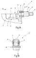
- the embodiment of the device 10 shown in Fig. 1 to 3 is provided with an adapter 16 made of conductive material and provided at one end with a lug 17 with a hole 18 and at the other end with a rail 19 which projects perpendicularly from the lug 17 and has undercut longitudinal edges 21, a pin contact 22 which is designed as a round pin and projects perpendicularly beyond the surface of the rail 19 remote from the lug 17 being held in the rail 19.
- the adapter 16 can be pushed or pressed onto a connecting finger 23 forming the terminal 12 or 13 of the battery 14 by its lug 17.
- a socket contact 26 which is designed as an annular socket and is held in an electrically insulating housing 27 of a plug member 25 can be electrically connected to the pin contact 22.
- the socket contact 26 can be of a conventional design and is fixed axially in the housing 27.
- the socket contact 26 is provided, in a central region, with an annular groove in which the segments of an internal region 28 of the housing 27 of an internal region 28 of the housing 27 engage; the longitudinally slit ends of the socket contact 26 also rest internally on an overlapping edge of this region 28 of the housing 27.
- the end region remote from the pin contact receiver of the socket contact 26 is provided with a blind hole in which the bared conductor 15 of the cable 11 can be plugged and clamped by crimping or soldered therein.
- the housing 27 is provided, round the internal region 28 holding the socket contact 26, with a sheath part 29 which is axially slit and provided with catch fingers 31 of a locking device 30 on two diametrically opposed regions.
- the leading free ends of the catch fingers 31 engage behind the undercut longitudinal edges 21 of the rail 19 of the adapter 16 (Fig. 1B) forming the locking device 30, when the socket contact 26 and pin contact 22 are assembled.
- This locking of plug 25 and adapter 16 eventually takes place automatically with the translational movement of the plug connector.
- a tool is required to release this locking in this embodiment, the automatic locking movement as well as the release or separating movement for unlocking taking place perpendicularly to the pure plug connector movement.
- the adapter 16' has a guide strip 36 which is spaced from and parallel to the pin contact 22 and passes into a slot 37 in the housing 27 of the plug 25 when pin contact 22 and socket contact 26 are plugged into one another.
- This guide connection 36, 37 prevents horizontal and/or axial movements during the translational movement of the plug connector.
- the catch fingers 31 of the locking device 30 interact with two diametrically opposed actuating levers 32 so the catch fingers 31 can be spread apart manually using the actuating lever 32 and the locking connection between plug 25" and adapter 16" can therefore be released.
- the adapter 16" is radially slit in the region of its lug 17" and is provided with radially projecting flanges 33 which are penetrated by a screw connection 34 so the lug 17" can be screwed tight on the connecting finger 23 of the battery terminal 12 or 13.
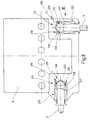
- the device 110 is formed by integrating a pin contact 122 designed as a round pin on the respective battery terminal 112 or 113.
- An intermediate rail 141 on whose free end projecting beyond the battery housing the pin contact 122 is formed, is formed on the battery terminal 112, 113 formed by a connecting finger 123. While the intermediate rail 141 is provided at the bottom end of the connecting finger 123 and extends parallel to the upper side of the battery housing, the pin contact 122 is formed perpendicularly on the underside of the intermediate rail 141, so as to point toward the foot of the battery 14.
- a plug 25' according to the variation in Fig. 4A is connected to the pin contact 122, the catch fingers 31' of the locking device 130 of the plug 25' engaging in a locking manner behind the intermediate rail 141. It will be appreciated that a plug 25 according to Fig. 43 or according to Fig. 1 to 3 can also be used with the pin contact 122.
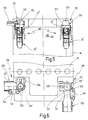
- Fig. 6 also shows that despite the arrangement of the pin contact 122 the connecting fingsrs 123 of the battery terminals 112, 113 can still be provided with a conventional clamp connection 43 provided with a lug 117', flanges 133 and a screw connection 134 as with the adapter 16" (Fig. 4B).
- the lug 117' is provided with clamp lugs 144 capable of clamping the conductor 15 therebetween via screw connections 145.
- the device 210 according to Fig. 8 and 9 has, as battery terminal 212, 213, a connecting finger 223 which has the pin contact 222 formed on a peripheral region.
- a guide strip 236 is provided at the bottom, parallel to the pin contact 222 arranged substantially halfway up the connecting finger 223.
- the connecting finger 223 is flattened at the point where the connecting finger 223 is formed and is provided, in the trailing region 248 remote from this flattened region 247 with a set of teeth 249 of which the diametrically opposed teeth facing the plug 225 serve for locking the catch fingers 231 of the locking device 230 of the plug 225.
- a variation of the plug 25 with locking device 30 according to Fig. 1 to 3 is used as plug 225 with locking device 230.
- a guide arrangement 236, 237 is provided as in the plug 25' in Fig. 4A, 4B. It will be appreciated that a plug provided with release levers on the locking device corresponding to the plug 25" in the partial figure 4B can also be used.
- Fig. 10 to 13 show the device 310 including a variation 310' in which the pin contact 322 at the bottom end of the connecting finger 323 of the battery terminal 12, 13 is provided in an outwardly projecting cranked manner.
- An intermediate rail 341 is provided between horizontally extending pin contact 322 and the forming region on the connecting finger 223 and, as shown in Fig. 13, leaves room for the use of a conventional clamp connection 343 on the connecting finger 223 designed similarly to the illustration in Fig. 5 to 7.
- the only difference is the adapted angular arrangement of lug 317 and clamp lugs 344.
- the pin contact 322 which is to be brought into translational connection with the socket contact 326 is held and axially fixed in a sleeve 351.
- the axial hold is provided by radial locking between internal catches of the sleeve 51 and annular grooves on the pin contact 322 in a manner not shown in detail.
- the sleeve 351 can additionally be fastened on the battery housing.
- the leading end of the sleeve 351 is designed as a bayonet fitting part 352 forming the locking device 330 with corresponding screw-threaded grooves and catch ends.
- the socket contact 326 is held in a plug 325 which has a cylindrical sleeve 353 with a rotating part 354 which is designed as a counter bayonet fitting part and forms the locking device 330 fitted axially unmovably round its leading end.
- the rotating part 354 has internally corresponding bayonet thread segments. This means that the device 310 performs the locking movement owing to the rotational movement of the bayonet fitting in addition to the translational plug connection movement. As known, a locking which can only be released again by opposing rotation is achieved during the bayonet fitting movement at the end.
- Fig. 12 shows a variation 310' of the device 310 in which the cylindrical sleeve 353 can be connected to an angle piece 356 through which the cable 11 is guided and sealed with a stopper 357 at the outlet end.
- a coloured and/or mechanical coding can be provided in a manner not shown in detail in the devices 10, 10', 110, 210, 310 according to the battery terminal 12, 112, 212, 312 or 13, 113, 213, 313 (plus or minus).
- pin contact 22, 122, 222, 322 and socket contact 26, 126, 226, 326 in one or other embodiment or variations thereof.
- An essential feature of all embodiments is that the plug connection movement of pin and socket contact is accompanied by a locking movement in a direction different from the former movement, wherein, in particular, the unlocking of the locking device 30, 130, 230, 330 can take place only in a direction which does not coincide with the plug connector movement.
Landscapes
- Details Of Connecting Devices For Male And Female Coupling (AREA)
- Connection Of Batteries Or Terminals (AREA)
Abstract
Description
Claims (16)
- Device for the plug-in connection of a single-conductor cable (11) to the terminal (12, 112, 212, 312; 13, 113, 213, 313) of a battery (14), in particular vehicle battery, wherein the conductor (15) of the cable (11) is clamped or soldered to a metallic insert (25, 125, 225, 325), with a plug connector device (10, 110, 210, 310) of which one contact (22, 122, 222, 322) is detachably connectable or rigidly connected to the battery terminal (12, 13) and of which the other contact (26, 126, 226, 326) is part of the metallic insert (25, 125, 225, 325), characterised in that one contact is designed as a round pin (22, 122, 222, 322) and the other contact, mating therewith, of the plug connector device (10, 110, 210, 310) is designed as a radially biased annular socket (26, 126, 226, 326) and in that round pin (22, 122, 222, 322) and annular socket (26, 126, 226, 326) are provided with locking members of a locking device (30, 130, 230, 330) which locking members are movable relative to one another for unlocking purposes in a direction different from the separation of round pin (22, 122, 222, 322) and annular socket (26, 126, 226, 326).
- Device, in which the battery terminal has a connecting finger (23, 123, 223, 323) according to claim 1, characterised in that the pin contact (22) is part of an adapter (16) of which the other end can be clamped to the connecting finger (23) of the battery terminal (12, 13).
- Device according to claim 2, characterised in that the pin contact (22) is offset in parallel in the opposite direction to the end of the adapter (16) connectable to the connecting finger (23).
- Device according to claim 1, characterised in that the pin contact (122) is rigidly connected, preferably cast with the battery terminal (12, 13).
- Device in which the battery terminal has a connecting finger according to claim 4, characterised in that the pin contact (122) is provided at the lower end of the connecting finger (123).
- Device in which the battery terminal has a connecting finger according to claim 4, characterised in that the pin contact (222) is arranged on a peripheral region of the connecting finger (223).
- Device according to claims 4 to 6, characterised in that the pin contact (122, 222, 322) projects horizontally outwardly from the battery housing.
- Device according to claims 4 to 6, characterised in that the pin contact (222) is oriented vertically to the side of the battery housing and toward its foot.
- Device according to at least one of the preceding claims, characterised in that the pin contact (22, 122, 222, 322) is fastened at an angle, preferably at right angles on a rail or ring forming a locking member for the plug member (25, 125, 225) containing the socket contact (26, 126, 226, 326).
- Device according to at least one of claims 1 to 9, characterised in that the socket contact (22, 122, 222) is held in a longitudinally locked manner in a plug housing (27, 127, 227) provided with a catch (31, 131, 231) which is at the front in the plug-in direction.
- Device according to claim 10, characterised in that the catch has at least two preferably diametrically opposed catch fingers, (31, 131, 231) which are shaped elastically on the plug housing (27, 127, 227).
- Device according to claim 11, characterised in that the catch fingers (31, 131, 231) are connected to release levers (32, 132, 232).
- Device according to claim 11 or 12, characterised in that the catch fingers (31, 131, 231) catch on an undercut rail, a toothed ring, a locking member or the like from which the pin contact projects.
- Device according to at least one of claims 10 to 13, characterised in that the plug housing member (27, 127, 227) parallel to the socket contact (26, 126, 226) has a slot (37, 137, 237) for a guide member (36, 136, 236) parallel to the pin contact (22, 122, 222).
- Device according to at least one of claims 1 to 8, characterised in that the socket contact (326) is held in a longitudinally locked manner in a plug housing (327) equipped with a bayonet assembly part (354) and in that a bayonet assembly part (352) mating therewith surrounds and axially holds the pin contact (322).
- Device according to claim 15, characterised in that the end of the plug housing (325) remote from the bayonet assembly part (354) can be connected to an angle piece (356).
Applications Claiming Priority (2)
| Application Number | Priority Date | Filing Date | Title |
|---|---|---|---|
| DE10012387A DE10012387C2 (en) | 2000-03-14 | 2000-03-14 | Arrangement for connecting a cable to a motor vehicle battery pole |
| DE10012387 | 2000-03-14 |
Publications (2)
| Publication Number | Publication Date |
|---|---|
| EP1134843A2 true EP1134843A2 (en) | 2001-09-19 |
| EP1134843A3 EP1134843A3 (en) | 2003-04-16 |
Family
ID=7634677
Family Applications (1)
| Application Number | Title | Priority Date | Filing Date |
|---|---|---|---|
| EP01104439A Withdrawn EP1134843A3 (en) | 2000-03-14 | 2001-02-27 | Device for the plug-in connection of a cable to a vehicle battery terminal |
Country Status (7)
| Country | Link |
|---|---|
| US (1) | US6629863B2 (en) |
| EP (1) | EP1134843A3 (en) |
| JP (1) | JP2001313104A (en) |
| KR (1) | KR20010092337A (en) |
| CA (1) | CA2339698A1 (en) |
| DE (1) | DE10012387C2 (en) |
| HK (1) | HK1042988A1 (en) |
Cited By (4)
| Publication number | Priority date | Publication date | Assignee | Title |
|---|---|---|---|---|
| US6607860B2 (en) * | 2001-01-24 | 2003-08-19 | Ewd, L.L.C. | Serviceable fused battery terminal |
| WO2009106581A3 (en) * | 2008-02-28 | 2009-10-29 | Viemme Srl | Improved electrical connection |
| CN101587998B (en) * | 2009-03-27 | 2010-12-01 | 四川华丰企业集团有限公司 | Fast-wiring connector |
| WO2014078834A1 (en) | 2012-11-19 | 2014-05-22 | Aquion Energy Inc. | Device and method for electrochemical device electrical interconnection |
Families Citing this family (28)
| Publication number | Priority date | Publication date | Assignee | Title |
|---|---|---|---|---|
| US6805593B2 (en) * | 2002-12-17 | 2004-10-19 | General Motors Corporation | Quick connect battery terminal |
| US7344421B1 (en) | 2005-06-06 | 2008-03-18 | Spencer Troy L | Quick release battery cable connector |
| US7688022B2 (en) | 2006-02-17 | 2010-03-30 | Lear Corporation | Energy management system for a vehicle |
| US7391664B2 (en) * | 2006-04-27 | 2008-06-24 | Ovonyx, Inc. | Page mode access for non-volatile memory arrays |
| US7381101B2 (en) * | 2006-08-25 | 2008-06-03 | Lear Corporation | Battery post connector |
| US7500888B2 (en) * | 2007-02-08 | 2009-03-10 | Lear Corporation | Battery post connector |
| US8476864B2 (en) * | 2007-06-13 | 2013-07-02 | Lear Corporation | Battery monitoring system |
| US8305034B2 (en) * | 2008-07-23 | 2012-11-06 | Lear Corporation | Battery monitoring system |
| JP5616111B2 (en) * | 2010-04-22 | 2014-10-29 | 矢崎総業株式会社 | Battery terminal with current sensor |
| EP2612399B1 (en) * | 2010-08-31 | 2020-06-24 | Delta Electronics (Thailand) Public Co., Ltd. | Cable plug and socket system for providing voltage selection |
| US9147871B2 (en) | 2011-08-01 | 2015-09-29 | Gerald A. Kowalski | Automotive battery connection system |
| US9105912B2 (en) * | 2012-05-21 | 2015-08-11 | Tyco Electronics Corporation | Boltless battery cell connection |
| DE102013005092B4 (en) | 2013-03-23 | 2020-10-01 | Audi Ag | Connector system for the mechanical connection and electrical contacting of two electrically conductive components |
| DE102015010039A1 (en) * | 2015-08-01 | 2017-02-02 | Daimler Ag | Contacting arrangement for connecting a battery pole with a connection element, battery pole, battery and connection element |
| US9873392B2 (en) * | 2015-08-17 | 2018-01-23 | Sumitomo Wiring Systems, Ltd. | Terminal connection assembly for vehicle power distribution device |
| CN105742839A (en) * | 2015-09-15 | 2016-07-06 | 秉岳电气(上海)有限公司 | Insulating and sealing electric branch connecting device |
| US10122004B2 (en) | 2017-03-16 | 2018-11-06 | Ford Global Technologies, Llc | Quick connect assembly for busbars in an electrified vehicle |
| US10518658B1 (en) * | 2018-11-06 | 2019-12-31 | Abb Schweiz Ag | Electrical vehicle battery recharging vehicle-side receptacle unit |
| CN109449671B (en) * | 2018-11-29 | 2023-09-26 | 一汽-大众汽车有限公司 | High-voltage connector |
| CN110611071B (en) * | 2019-09-09 | 2021-11-23 | 国网河北省电力有限公司 | Connector for storage battery and using method thereof |
| KR102903843B1 (en) * | 2020-05-13 | 2025-12-23 | 삼성에스디아이 주식회사 | Battery pack |
| CN111668441B (en) * | 2020-05-19 | 2022-03-11 | 合肥国轩高科动力能源有限公司 | Cylindrical battery seals steel ball anchor clamps tray mechanism |
| CN111916959B (en) * | 2020-07-16 | 2025-01-24 | 江西巴斯巴新能源技术有限公司 | A connector |
| CN112713358A (en) * | 2020-12-11 | 2021-04-27 | 安徽力普拉斯电源技术有限公司 | Spliced storage battery |
| US11996640B2 (en) * | 2021-10-25 | 2024-05-28 | Custom Battery Cables, LLC | Battery terminal connector |
| CN120322921A (en) | 2022-12-08 | 2025-07-15 | 豪倍公司 | Electrical connector with interlocking device |
| CN117895256B (en) * | 2024-03-15 | 2024-07-26 | 国网山东省电力公司潍坊市寒亭区供电公司 | A cable connector |
| CN120090005A (en) * | 2025-03-03 | 2025-06-03 | 镇江华扬机车车辆附件有限公司 | A power connector fastening plug plate assembly for a vulcanizing machine |
Family Cites Families (30)
| Publication number | Priority date | Publication date | Assignee | Title |
|---|---|---|---|---|
| US3287031A (en) * | 1964-09-21 | 1966-11-22 | William H Simmons | Indexed keyed connection |
| US3933406A (en) * | 1974-01-04 | 1976-01-20 | Ford Motor Company | Electrical connector block assembly having overcenter locking |
| US3909301A (en) * | 1974-01-21 | 1975-09-30 | Gould Inc | Positive displacement bonding |
| GB8403412D0 (en) * | 1984-02-09 | 1984-03-14 | Lucas Ind Plc | Electrical connectors |
| DE3532044A1 (en) * | 1985-09-09 | 1987-03-19 | Vdo Schindling | POLE CLAMP |
| DE3821861C1 (en) * | 1988-06-29 | 1989-09-21 | Accumulatorenwerke Hoppecke Carl Zoellner & Sohn Gmbh & Co Kg, 5790 Brilon, De | |
| US4906205A (en) * | 1988-10-31 | 1990-03-06 | Stephen C. Burgess | Jumper cable safety means |
| US5066905A (en) * | 1988-11-14 | 1991-11-19 | Baton Labs, Inc. | Battery cable assembly with in-line switch |
| US4895530A (en) * | 1989-02-24 | 1990-01-23 | Molex Incorporated | Quick disconnect automotive battery connector |
| US4964819A (en) * | 1989-08-15 | 1990-10-23 | Caraballo Damian F | Terminal connector clamp |
| JP2969887B2 (en) * | 1990-09-28 | 1999-11-02 | 松下電器産業株式会社 | Lead storage battery |
| DE4408834A1 (en) * | 1994-03-16 | 1995-09-21 | Eifelwerk Heinrich Stein Gmbh | Terminal connector for storage battery |
| US5496197A (en) * | 1994-06-24 | 1996-03-05 | Grivet; Michael J. | Battery connector assembly |
| US5612659A (en) * | 1994-08-08 | 1997-03-18 | Quicksilver Engineering | Battery protecting circuit breaker |
| DE69519611T2 (en) * | 1994-08-24 | 2001-04-19 | The Whitaker Corp., Wilmington | Battery clamp with fuse for motor vehicles and their connection |
| GB9423021D0 (en) * | 1994-11-15 | 1995-01-04 | Amp Gmbh | Through-wall electrical connector housing |
| EP0867054B1 (en) * | 1995-11-20 | 1999-08-18 | Wilhelm Sihn jr. KG. | Coaxial plug connector for communications technology, in particular in motor vehicles |
| DE19609571A1 (en) * | 1995-11-20 | 1997-05-22 | Sihn Jr Kg Wilhelm | Coaxial connector for communication technology in automobiles |
| IT237299Y1 (en) * | 1995-11-22 | 2000-09-05 | Cavis Srl | TERMINAL STRUCTURE FOR CONNECTING THE POLES OF A BATTERY |
| US5707250A (en) * | 1995-12-15 | 1998-01-13 | Smithson; Herbert L. | Apparatus and method for storage battery cable connector |
| FR2745123B1 (en) * | 1996-02-21 | 1998-05-15 | Socop Sa | CONNECTOR FOR BATTERY TERMINAL FOR CONNECTING THE OPERATING CIRCUITS TO THEIR RESPECTIVE TERMINAL SO THAT THE TERMINAL CONNECTOR ONCE MOUNTED IS NO LONGER DISASSEMBLED |
| US5597331A (en) * | 1996-02-23 | 1997-01-28 | Ford Motor Company | Battery connector for an automotive electrical system |
| US5713765A (en) * | 1996-04-23 | 1998-02-03 | Nugent; Steven F. | High-current audio connector |
| ES1035407Y (en) * | 1996-10-21 | 1997-10-16 | Mecanismos Aux Ind | PERFECTED BATERIA TERMINAL. |
| US5885088A (en) * | 1997-07-14 | 1999-03-23 | Molex Incorporated | Electrical connector assembly with polarization means |
| JPH1154184A (en) * | 1997-08-04 | 1999-02-26 | Sumitomo Wiring Syst Ltd | Battery terminal |
| US5980334A (en) * | 1998-09-02 | 1999-11-09 | Pyles; Felix A. | Electric storage battery connector assembly |
| DE19917549C1 (en) * | 1999-04-19 | 2000-11-02 | Dunkel Otto Gmbh | Electrical jack-plug connector e.g. for electrical device lead cable, has sliding locking sleeve rotated to bring raised elements into contact with locking claws for securing plug part in cooperating socket part |
| US6162098A (en) * | 2000-02-02 | 2000-12-19 | Cheng; Wen Tzung | Modified connector for car battery |
| US6459233B1 (en) * | 2001-04-20 | 2002-10-01 | Shih Tsung Liang | Cable attachment assembly for battery of vehicle |
-
2000
- 2000-03-14 DE DE10012387A patent/DE10012387C2/en not_active Expired - Fee Related
-
2001
- 2001-02-27 EP EP01104439A patent/EP1134843A3/en not_active Withdrawn
- 2001-03-08 CA CA002339698A patent/CA2339698A1/en not_active Abandoned
- 2001-03-09 US US09/803,326 patent/US6629863B2/en not_active Expired - Fee Related
- 2001-03-13 JP JP2001071024A patent/JP2001313104A/en active Pending
- 2001-03-14 KR KR1020010013230A patent/KR20010092337A/en not_active Withdrawn
-
2002
- 2002-03-18 HK HK02102053.8A patent/HK1042988A1/en unknown
Cited By (6)
| Publication number | Priority date | Publication date | Assignee | Title |
|---|---|---|---|---|
| US6607860B2 (en) * | 2001-01-24 | 2003-08-19 | Ewd, L.L.C. | Serviceable fused battery terminal |
| WO2009106581A3 (en) * | 2008-02-28 | 2009-10-29 | Viemme Srl | Improved electrical connection |
| CN101587998B (en) * | 2009-03-27 | 2010-12-01 | 四川华丰企业集团有限公司 | Fast-wiring connector |
| WO2014078834A1 (en) | 2012-11-19 | 2014-05-22 | Aquion Energy Inc. | Device and method for electrochemical device electrical interconnection |
| US9478787B2 (en) | 2012-11-19 | 2016-10-25 | Aquion Energy Inc. | Device and method for electrochemical device electrical interconnection |
| EP2920829A4 (en) * | 2012-11-19 | 2016-12-07 | Aquion Energy Inc | DEVICE AND METHOD FOR ELECTRICAL INTERCONNECTION OF ELECTROCHEMICAL DEVICE |
Also Published As
| Publication number | Publication date |
|---|---|
| US6629863B2 (en) | 2003-10-07 |
| EP1134843A3 (en) | 2003-04-16 |
| DE10012387C2 (en) | 2002-10-02 |
| US20010023037A1 (en) | 2001-09-20 |
| KR20010092337A (en) | 2001-10-24 |
| JP2001313104A (en) | 2001-11-09 |
| DE10012387A1 (en) | 2001-10-04 |
| HK1042988A1 (en) | 2002-08-30 |
| CA2339698A1 (en) | 2001-09-14 |
Similar Documents
| Publication | Publication Date | Title |
|---|---|---|
| HK1042988A1 (en) | Device for the plug-in connection of a cable to a vehicle battery terminal | |
| US6948963B2 (en) | Securing device and method | |
| US4736999A (en) | Electrical connector with component keying system | |
| US3986765A (en) | Power cord connector | |
| US6206714B1 (en) | Plug and adapter for existing single pole electrical receptacle | |
| EP1589619A1 (en) | Connector | |
| JPH0369147B2 (en) | ||
| JPH0536771U (en) | Waterproof structure of switch connector | |
| US4270827A (en) | Battery cable connector | |
| US5030106A (en) | Battery jumper cable clamp | |
| JPH04212271A (en) | Spring clip electric connector | |
| EP0001885A1 (en) | Electrical connector assembly including latching means | |
| EP1811603A1 (en) | A body of a contact-holder unit for an electrical connection socket/plug | |
| CN103843200A (en) | Electrical connector system and method of making same | |
| US6722922B2 (en) | Heavy duty electrical connector | |
| EP1049212B1 (en) | Plug for electrical connection between a towing vehicle and a trailer | |
| CN110034442B (en) | Electrical connector | |
| CN103597663B (en) | Connector assemblies for making electrical connections with wires | |
| US9608387B2 (en) | Shield connector arrangement | |
| EP0991138A2 (en) | An electrical connector and earthing element | |
| EP0063120B1 (en) | Improvements relating to electrical plugs | |
| WO1982003295A1 (en) | Electrical connectors | |
| EP0101257B1 (en) | Lampholder | |
| GB2098411A (en) | Electrical plugs | |
| US5749745A (en) | Adapter connector and camera assembly equipped with said adapter connector |
Legal Events
| Date | Code | Title | Description |
|---|---|---|---|
| PUAI | Public reference made under article 153(3) epc to a published international application that has entered the european phase |
Free format text: ORIGINAL CODE: 0009012 |
|
| AK | Designated contracting states |
Kind code of ref document: A2 Designated state(s): AT BE CH CY DE DK ES FI FR GB GR IE IT LI LU MC NL PT SE TR |
|
| AX | Request for extension of the european patent |
Free format text: AL;LT;LV;MK;RO;SI |
|
| PUAL | Search report despatched |
Free format text: ORIGINAL CODE: 0009013 |
|
| AK | Designated contracting states |
Designated state(s): AT BE CH CY DE DK ES FI FR GB GR IE IT LI LU MC NL PT SE TR |
|
| AX | Request for extension of the european patent |
Extension state: AL LT LV MK RO SI |
|
| 17P | Request for examination filed |
Effective date: 20030507 |
|
| 17Q | First examination report despatched |
Effective date: 20030919 |
|
| AKX | Designation fees paid |
Designated state(s): AT BE CH CY DE DK ES FI FR GB GR IE IT LI LU MC NL PT SE TR |
|
| GRAP | Despatch of communication of intention to grant a patent |
Free format text: ORIGINAL CODE: EPIDOSNIGR1 |
|
| STAA | Information on the status of an ep patent application or granted ep patent |
Free format text: STATUS: THE APPLICATION IS DEEMED TO BE WITHDRAWN |
|
| 18D | Application deemed to be withdrawn |
Effective date: 20041202 |
|
| REG | Reference to a national code |
Ref country code: HK Ref legal event code: WD Ref document number: 1042988 Country of ref document: HK |