EP1134842A2 - Zusammenbau eines Anschlussblocks mit integrierter Sammelschiene - Google Patents
Zusammenbau eines Anschlussblocks mit integrierter Sammelschiene Download PDFInfo
- Publication number
- EP1134842A2 EP1134842A2 EP01301978A EP01301978A EP1134842A2 EP 1134842 A2 EP1134842 A2 EP 1134842A2 EP 01301978 A EP01301978 A EP 01301978A EP 01301978 A EP01301978 A EP 01301978A EP 1134842 A2 EP1134842 A2 EP 1134842A2
- Authority
- EP
- European Patent Office
- Prior art keywords
- terminal block
- block assembly
- outer shell
- spring clamps
- electrical wire
- Prior art date
- Legal status (The legal status is an assumption and is not a legal conclusion. Google has not performed a legal analysis and makes no representation as to the accuracy of the status listed.)
- Withdrawn
Links
- 238000004519 manufacturing process Methods 0.000 claims description 11
- 230000008878 coupling Effects 0.000 claims 1
- 238000010168 coupling process Methods 0.000 claims 1
- 238000005859 coupling reaction Methods 0.000 claims 1
- 238000010586 diagram Methods 0.000 description 2
- 238000000034 method Methods 0.000 description 2
- 230000004075 alteration Effects 0.000 description 1
- 230000003190 augmentative effect Effects 0.000 description 1
- 239000004020 conductor Substances 0.000 description 1
- 238000010276 construction Methods 0.000 description 1
- 230000007812 deficiency Effects 0.000 description 1
- 238000009429 electrical wiring Methods 0.000 description 1
- 230000007935 neutral effect Effects 0.000 description 1
- 125000006850 spacer group Chemical group 0.000 description 1
- 238000006467 substitution reaction Methods 0.000 description 1
Images


Classifications
-
- H—ELECTRICITY
- H01—ELECTRIC ELEMENTS
- H01R—ELECTRICALLY-CONDUCTIVE CONNECTIONS; STRUCTURAL ASSOCIATIONS OF A PLURALITY OF MUTUALLY-INSULATED ELECTRICAL CONNECTING ELEMENTS; COUPLING DEVICES; CURRENT COLLECTORS
- H01R4/00—Electrically-conductive connections between two or more conductive members in direct contact, i.e. touching one another; Means for effecting or maintaining such contact; Electrically-conductive connections having two or more spaced connecting locations for conductors and using contact members penetrating insulation
- H01R4/28—Clamped connections, spring connections
- H01R4/48—Clamped connections, spring connections utilising a spring, clip, or other resilient member
- H01R4/4809—Clamped connections, spring connections utilising a spring, clip, or other resilient member using a leaf spring to bias the conductor toward the busbar
- H01R4/484—Spring housing details
- H01R4/4842—Spring housing details the spring housing being provided with a single opening for insertion of a spring-activating tool
-
- H—ELECTRICITY
- H01—ELECTRIC ELEMENTS
- H01R—ELECTRICALLY-CONDUCTIVE CONNECTIONS; STRUCTURAL ASSOCIATIONS OF A PLURALITY OF MUTUALLY-INSULATED ELECTRICAL CONNECTING ELEMENTS; COUPLING DEVICES; CURRENT COLLECTORS
- H01R4/00—Electrically-conductive connections between two or more conductive members in direct contact, i.e. touching one another; Means for effecting or maintaining such contact; Electrically-conductive connections having two or more spaced connecting locations for conductors and using contact members penetrating insulation
- H01R4/28—Clamped connections, spring connections
- H01R4/48—Clamped connections, spring connections utilising a spring, clip, or other resilient member
- H01R4/4809—Clamped connections, spring connections utilising a spring, clip, or other resilient member using a leaf spring to bias the conductor toward the busbar
- H01R4/4811—Spring details
- H01R4/4816—Spring details the spring shape preventing insertion of the conductor end when the spring is unbiased
-
- H—ELECTRICITY
- H01—ELECTRIC ELEMENTS
- H01R—ELECTRICALLY-CONDUCTIVE CONNECTIONS; STRUCTURAL ASSOCIATIONS OF A PLURALITY OF MUTUALLY-INSULATED ELECTRICAL CONNECTING ELEMENTS; COUPLING DEVICES; CURRENT COLLECTORS
- H01R4/00—Electrically-conductive connections between two or more conductive members in direct contact, i.e. touching one another; Means for effecting or maintaining such contact; Electrically-conductive connections having two or more spaced connecting locations for conductors and using contact members penetrating insulation
- H01R4/28—Clamped connections, spring connections
- H01R4/48—Clamped connections, spring connections utilising a spring, clip, or other resilient member
- H01R4/4809—Clamped connections, spring connections utilising a spring, clip, or other resilient member using a leaf spring to bias the conductor toward the busbar
- H01R4/4846—Busbar details
- H01R4/485—Single busbar common to multiple springs
Definitions
- the present invention is directed, in general, to a terminal block assembly and, more specifically, to a terminal block assembly that has a plurality of spring clips to receive electrical wire terminations.
- Telecommunication and electrical distribution networks are frequently provided with common collection and distribution points at which electrical signals in the network of wires are gathered together or distributed.
- the most frequently used termination point for the network of electrical wires takes the form of a collective connection device.
- Collective connection devices typically have a frame to which are attached the terminals used to terminate electrical wiring and route or distribute electrical signals through the network.
- a feature shared by all such devices is that a mechanism must be provided to accept and hold the terminal ends of the wires that form the network.
- terminal blocks mounted on the collective connection device. Because the network can consist of a large number of electrical wires, the collective connection device must have sufficient capacity to receive all the electrical wire terminations in the network. These terminal blocks are usually mounted in rows on the collective connection device frame in direct mechanical and electrical contact with a bus bar coupled to the collective connection device.
- Terminal blocks are designed to receive either flexible or rigid wire conductors. In most cases, the terminal block uses a spring clamp or clip to capture and secure the wire termination. Because the most frequently used terminal block is designed to receive only a single electrical wire termination, it is not unusual for a collective connection device to have a large number of terminal blocks that occupy a considerable amount of bus bar space. Typically terminal blocks are located adjacent to other terminal blocks in a tightly arranged relationship. In large distribution systems the space devoted to terminal blocks can be the limiting factor on the size of the collective connection device and dictate the amount of facility space that is required to house the device.
- the most widely used terminal block design accommodates a single spring clamp configured to secure a single electrical wire termination.
- the spring clamp is housed in a plastic cover that also serves to secure the terminal block to the bus bar.
- In the front of the plastic cover are two apertures, one of which provides access to the spring clamp to receive and secure the electrical wire termination.
- the second aperture receives the end of a pry tool, such as a screwdriver, that is inserted in the spring clamp to urge the clamp into an open position while an electrical wire termination is inserted. After the end of the electrical wire is inserted into the open spring clamp, the pry tool is removed and the spring clamp is permitted to return to a neutral position to capture and secure the electrical termination in the clamp.
- the present invention provides for a terminal block assembly to use in receiving a plurality of electrical wire terminations.
- the terminal block assembly comprises: (1) an outer shell having a plurality of apertures, (2) a plurality of spring clamps arranged laterally within said outer shell, said plurality of spring clamps associated with corresponding ones of said plurality of apertures and configured to receive and hold said plurality of electrical wire terminations and (3) a pry support, coupled to said outer shell and associated with said spring clamps, that is adapted to support, and act as a fulcrum for, a pry tool to urge at least one of said plurality of spring clips open to receive one of said plurality of electrical wire terminations.
- the present invention therefore introduces the broad concept of a terminal block assembly with a pry support incorporated into the assembly that can be used as a fulcrum to open spring clamps to receive an electrical wire termination.
- a pry support into the assembly avoids having to use the case of the terminal block assembly to support a pry tool to open a spring clamp. This provides the advantage of adding to the life of a terminal block assembly by providing a stronger, more durable device.
- the spring clamps in the terminal block assembly are associated with corresponding ones of the plurality of apertures configured to provide an access point for the pry tool.
- other apertures are associated with the portion of the spring clamps that receive the electrical wire terminations.
- the plurality of spring clamps to be WAGOJ cage clamp springs.
- a bus bar located within the outer shell of the terminal block assembly is a bus bar that provides electrical interconnectivity with a plurality of the spring clamps.
- the terminal block assembly includes a plurality of bus bars within the outer shell. Each one of the plurality of bus bars electrically contacts at least one of the spring clamps.
- the terminal block assembly is couplable to an electronics equipment chassis.
- One aspect of the invention provides for a bullet connector to be associated with the terminal block assembly. This permits the terminal block assembly to be couplable to the electronics equipment chassis by the bullet connector.
- the present invention also provides a method of manufacturing a terminal block assembly to receive a plurality of electrical wire terminations.
- an outer shell having a plurality of apertures is formed.
- a plurality of spring clamps is arranged laterally within the outer shell so that the plurality of spring clamps are associated with the plurality of apertures.
- the plurality of spring clamps is configured to receive and hold the plurality of electrical wire terminations.
- a pry support is coupled to the outer shell and associated with the plurality of spring clamps. The pry support is adapted to support, and act as a fulcrum for, a pry tool that can be used to urge at least one of the plurality of spring clips open in order to receive one of the plurality of electrical wire terminations.
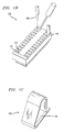
- FIGURE 1A illustrated is an exploded isometric view of an embodiment of a terminal block assembly 100 adapted to receive a plurality of electrical wire terminations.
- the illustrated terminal block assembly 100 has four major components as well as several spring clamps 150.
- the four major components are: an outer shell 110, a pry support 120, a bus bar 130 and an end cap 140.
- Mounted on the bus bar 130 are a plurality of laterally-arranged spring clamps 150.
- the spring clamps 150 are mounted on the bus bar 130 by placing the individual spring clamps 150 over a spring clamp support 135 located on the bus bar 130 that is configured to receive and secure the spring clamps 150 in position.
- FIGURE 1B illustrated is an isometric view of the terminal block assembly 100 of FIGURE 1A.
- the outer shell 110 Arranged laterally within the outer shell 110 of the terminal block assembly 100 are a plurality of spring clamps 150 (not visible).
- the outer shell 110 has a plurality of apertures 115 that provide access to the spring clamps 150 associated with corresponding apertures 115.
- the spring clamps 150 are configured to receive an electrical wire termination 160 through an associated aperture 115.
- the apertures 115 are arranged in pairs, each pair associated with an individual spring clamp 150.
- One aperture 115 in the pair receives the electrical wire termination 160 while the second aperture 115 provides a pry tool 170 access to the spring clamp 150.
- the pry tool 170 is used to urge the spring clamp 150 into an open position. While the spring clamp 150 is in an open position, an electrical wire termination 161 is inserted into the open spring clamp 150 through the second aperture 115 associated with that particular spring clamp 150.
- FIGURE 1C illustrated is the embodiment of a spring clamp 150 used in the terminal block assembly 100 that is illustrated in FIGURES 1A and 1B.
- the spring clamp illustrated is a WAGOJ cage clamp spring.
- the spring clamps 150 can be configured to receive other configurations of an electrical wire termination 161.
- the WAGOTM clamp 150 has an aperture 151 thereon that receives the spring clamp support 135 on the bus bar 130.
- the spring clamp support 135 is configured to support and secure the spring clamp 150 in a predetermined position.
- the pry support 120 is coupled to the outer shell 110 and positioned so that it is associated with the plurality of spring clamps 150.
- the illustrated pry support 110 has individual supports 125, each of which is associated with a spring clamp 150.
- Each individual support 125 is positioned so that it serves as a fulcrum for the pry tool 170 to act against when the spring clamp 150 associated with that particular support 125 is being urged into a open position.
- Those of ordinary skill in the art will understand that other configurations of a pry support 120 can be used and still be within the scope of the present invention.
- the spring clamps 150 in the terminal block assembly 100 when assembled the spring clamps 150 in the terminal block assembly 100 are positioned so they each are associated with an individual support 125.
- the pry support 120 also secures the spring clamps 150 into position by capturing them between the outer shell 110 and the pry support 120.
- spacer legs 145 on the end cap 140 are positioned between the bottom of the pry support 120 and the inside surface of the bus bar 130.
- the end cap 140 secures the outer shell 110, the pry support 130 and the bus bar 140 together in a single unit while securing the spring clamps 150 in a lateral position inside the outer shell 110.
- the illustrated embodiment of a terminal block assembly has the bus bar 130 located within the outer shell 110 in electrical contact with the plurality of spring clips 150 located therein.
- FIGURE 2 illustrated is an isometric view of a portion of an electronics equipment chassis 200 to which a terminal block assembly 100 is coupled.
- the illustrated electronics equipment chassis 200 is part of collective connection apparatus with a frame 210 to which the terminal block assembly 100 is coupled so that it can receive a plurality of electrical wire terminations 160.
- FIGURE 3A illustrates an isometric view 310 and a planar side view 320 of the embodiment of the-terminal block assembly 100 previously described herein.
- the illustrated embodiment depicts a single bus bar 130 located within the outer shell 110 electrically contacting the plurality of spring clamps 150 (not visible) arranged laterally within the outer shell 110.
- Each aperture 115 in the outer shell is associated with a spring clamp 150 in contact with the bus bar 130.
- FIGURE 3B illustrates an isometric 330 and planar side view 340 of an embodiment of a terminal block assembly 100 with multiple bus bars 131, 132, 133, 134 located within the outer shell 110.
- the illustrated terminal block assembly 100 has four bus bars 131-134, but those of ordinary skill in the art will understand that a terminal block assembly 100 can have any number of bus bars 130 within the outer shell 110 and be within the scope of the present invention. Multiple bus bar 131-134 configurations are particularly advantageous, because each bus bars 131-134 can be carrying a different current or be of a different voltage potential.
- Each of the bus bars 131-134 is associated with apertures 115 associated with spring clamps 150 arranged laterally with the outer shell 110 that are in electrical contact with one of the bus bars 131-134.
- FIGURE 3C illustrates an isometric view 350 and a planar side view 360 of a terminal block assembly 100 with bullet type connectors 370.
- the bullet type connectors 370 are fastened to the bus bar and are configured to connect the terminal block assembly 100 to a frame or chassis of a collective connection device.
- FIGURE 4 illustrated is a flow diagram of one embodiment of a method of manufacturing 400 a terminal block assembly to receive a plurality of electrical wire terminations.
- the method commences with a start step 410.
- an outer shell is formed with a plurality of apertures in a form outer shell step 420.
- a provide and arrange spring clamps step 430 a plurality of spring clamps configured to receive and hold a plurality of electrical wire terminations is provided and arranged laterally within the outer shell so that the spring clamps are associated with the plurality of apertures in the outer shell.
- a pry support is formed that is coupled to the outer shell and associated with the plurality of spring clamps.
- the pry support is formed so that it is adapted to support, and act as a fulcrum for, a pry tool that can be used to urge at least one of the plurality of spring clips open in order to receive one of the plurality of electrical wire terminations.
- the manufacturing method concludes with an end step 450.
Landscapes
- Connections Arranged To Contact A Plurality Of Conductors (AREA)
- Connection Or Junction Boxes (AREA)
Applications Claiming Priority (2)
| Application Number | Priority Date | Filing Date | Title |
|---|---|---|---|
| US52471000A | 2000-03-14 | 2000-03-14 | |
| US524710 | 2000-03-14 |
Publications (1)
| Publication Number | Publication Date |
|---|---|
| EP1134842A2 true EP1134842A2 (de) | 2001-09-19 |
Family
ID=24090351
Family Applications (1)
| Application Number | Title | Priority Date | Filing Date |
|---|---|---|---|
| EP01301978A Withdrawn EP1134842A2 (de) | 2000-03-14 | 2001-03-05 | Zusammenbau eines Anschlussblocks mit integrierter Sammelschiene |
Country Status (2)
| Country | Link |
|---|---|
| EP (1) | EP1134842A2 (de) |
| JP (1) | JP2001307790A (de) |
Cited By (1)
| Publication number | Priority date | Publication date | Assignee | Title |
|---|---|---|---|---|
| US7909633B1 (en) | 2009-09-15 | 2011-03-22 | Fisher-Rosemount Systems, Inc. | Wire connection apparatus |
-
2001
- 2001-03-05 EP EP01301978A patent/EP1134842A2/de not_active Withdrawn
- 2001-03-14 JP JP2001071398A patent/JP2001307790A/ja active Pending
Cited By (1)
| Publication number | Priority date | Publication date | Assignee | Title |
|---|---|---|---|---|
| US7909633B1 (en) | 2009-09-15 | 2011-03-22 | Fisher-Rosemount Systems, Inc. | Wire connection apparatus |
Also Published As
| Publication number | Publication date |
|---|---|
| JP2001307790A (ja) | 2001-11-02 |
Similar Documents
| Publication | Publication Date | Title |
|---|---|---|
| US5086368A (en) | Connector bank with voltage surge protection | |
| US5627721A (en) | Protector cartridge for modular connector blocks | |
| US5114356A (en) | Connecting block for the telecommunication and data technology | |
| US8192235B2 (en) | Cable connector for printed circuit boards | |
| EP0743713A2 (de) | Haltevorrichtung und Masseschiene für einen Verbindungsblock | |
| US7037118B2 (en) | Access module | |
| AU599730B2 (en) | Connector bank for telecommunication devices | |
| US6193556B1 (en) | Electrical terminal array with insulation displacement connectors and surge arrestors | |
| US7632133B2 (en) | Cross connect terminal block | |
| CN105474469A (zh) | 用于特别是外部路由总线系统的承插结构的接触元件 | |
| US5816854A (en) | Mounting bracket for connector block | |
| CN105794046B (zh) | 插接器触头支架 | |
| CN103384942A (zh) | 电气串联端子和串联端子块 | |
| MXPA05001398A (es) | Modulo de conexion de distribuidores para la tecnica de telecomunicaciones y la tecnica de datos. | |
| CN101897085A (zh) | 用于形成插座的模块系统 | |
| US7397673B1 (en) | Surge suppression device with replaceable surge suppression modules | |
| JPH0917466A (ja) | 2線挿入の機能を有する絶縁排除端子 | |
| JPH1083851A (ja) | 接地モジュール | |
| US6709299B2 (en) | Plug-in module, carrier plate and relay arrangement | |
| RU2231183C2 (ru) | Электрический соединитель | |
| JP2005527140A (ja) | 電気通信端子モジュール | |
| EP1134842A2 (de) | Zusammenbau eines Anschlussblocks mit integrierter Sammelschiene | |
| RU2007105133A (ru) | Вставное устройство защиты от перенапряжений | |
| WO2012032464A1 (en) | Socket separating device, line distribution module and telecommunication line distribution assembly | |
| AU762700B2 (en) | Protection connector for a telecommunications equipment item |
Legal Events
| Date | Code | Title | Description |
|---|---|---|---|
| PUAI | Public reference made under article 153(3) epc to a published international application that has entered the european phase |
Free format text: ORIGINAL CODE: 0009012 |
|
| AK | Designated contracting states |
Kind code of ref document: A2 Designated state(s): AT BE CH CY DE DK ES FI FR GB GR IE IT LI LU MC NL PT SE TR |
|
| AX | Request for extension of the european patent |
Free format text: AL;LT;LV;MK;RO;SI |
|
| STAA | Information on the status of an ep patent application or granted ep patent |
Free format text: STATUS: THE APPLICATION HAS BEEN WITHDRAWN |
|
| 18W | Application withdrawn |
Withdrawal date: 20011026 |