EP1134818B1 - Safety device for sealed battery and sealed battery using it - Google Patents
Safety device for sealed battery and sealed battery using it Download PDFInfo
- Publication number
- EP1134818B1 EP1134818B1 EP99972790A EP99972790A EP1134818B1 EP 1134818 B1 EP1134818 B1 EP 1134818B1 EP 99972790 A EP99972790 A EP 99972790A EP 99972790 A EP99972790 A EP 99972790A EP 1134818 B1 EP1134818 B1 EP 1134818B1
- Authority
- EP
- European Patent Office
- Prior art keywords
- plate
- shield plate
- pressure
- safety device
- lid
- Prior art date
- Legal status (The legal status is an assumption and is not a legal conclusion. Google has not performed a legal analysis and makes no representation as to the accuracy of the status listed.)
- Expired - Lifetime
Links
Images



Classifications
-
- H—ELECTRICITY
- H01—ELECTRIC ELEMENTS
- H01M—PROCESSES OR MEANS, e.g. BATTERIES, FOR THE DIRECT CONVERSION OF CHEMICAL ENERGY INTO ELECTRICAL ENERGY
- H01M50/00—Constructional details or processes of manufacture of the non-active parts of electrochemical cells other than fuel cells, e.g. hybrid cells
- H01M50/50—Current conducting connections for cells or batteries
- H01M50/572—Means for preventing undesired use or discharge
-
- H—ELECTRICITY
- H01—ELECTRIC ELEMENTS
- H01M—PROCESSES OR MEANS, e.g. BATTERIES, FOR THE DIRECT CONVERSION OF CHEMICAL ENERGY INTO ELECTRICAL ENERGY
- H01M50/00—Constructional details or processes of manufacture of the non-active parts of electrochemical cells other than fuel cells, e.g. hybrid cells
- H01M50/30—Arrangements for facilitating escape of gases
- H01M50/342—Non-re-sealable arrangements
- H01M50/3425—Non-re-sealable arrangements in the form of rupturable membranes or weakened parts, e.g. pierced with the aid of a sharp member
-
- H—ELECTRICITY
- H01—ELECTRIC ELEMENTS
- H01M—PROCESSES OR MEANS, e.g. BATTERIES, FOR THE DIRECT CONVERSION OF CHEMICAL ENERGY INTO ELECTRICAL ENERGY
- H01M10/00—Secondary cells; Manufacture thereof
- H01M10/05—Accumulators with non-aqueous electrolyte
- H01M10/052—Li-accumulators
-
- H—ELECTRICITY
- H01—ELECTRIC ELEMENTS
- H01M—PROCESSES OR MEANS, e.g. BATTERIES, FOR THE DIRECT CONVERSION OF CHEMICAL ENERGY INTO ELECTRICAL ENERGY
- H01M2200/00—Safety devices for primary or secondary batteries
- H01M2200/10—Temperature sensitive devices
- H01M2200/106—PTC
-
- H—ELECTRICITY
- H01—ELECTRIC ELEMENTS
- H01M—PROCESSES OR MEANS, e.g. BATTERIES, FOR THE DIRECT CONVERSION OF CHEMICAL ENERGY INTO ELECTRICAL ENERGY
- H01M2200/00—Safety devices for primary or secondary batteries
- H01M2200/20—Pressure-sensitive devices
-
- Y—GENERAL TAGGING OF NEW TECHNOLOGICAL DEVELOPMENTS; GENERAL TAGGING OF CROSS-SECTIONAL TECHNOLOGIES SPANNING OVER SEVERAL SECTIONS OF THE IPC; TECHNICAL SUBJECTS COVERED BY FORMER USPC CROSS-REFERENCE ART COLLECTIONS [XRACs] AND DIGESTS
- Y02—TECHNOLOGIES OR APPLICATIONS FOR MITIGATION OR ADAPTATION AGAINST CLIMATE CHANGE
- Y02E—REDUCTION OF GREENHOUSE GAS [GHG] EMISSIONS, RELATED TO ENERGY GENERATION, TRANSMISSION OR DISTRIBUTION
- Y02E60/00—Enabling technologies; Technologies with a potential or indirect contribution to GHG emissions mitigation
- Y02E60/10—Energy storage using batteries
Definitions
- the present invention relates to a safety device for explosion-proof of a closed battery and a closed battery with the safety device.
- the secondary battery has a high electro motive force, the secondary battery would explode in case of an increased inner pressure caused by chemical reaction in an electrode member with a positive electrode and a negative electrode installed in an outer container.
- a non-water electrolytic solution battery such as a lithium secondary battery is in an overcharge condition or a large amount of electric current is flown into the battery in a short circuit condition caused by a wrong operation
- non-water electrolytic solution is solved in the electrode member and gas is produced.
- the gas is continuously produced in the outer container and an inner pressure of the outer container increases, the battery would explode in finally.
- a positive electrode lid provided at an edge of an outer container comprises a porous metallic plate effected as the innermost lid and connected to a positive electrode of an electrode member through a positive electrode lead, a metallic explosion-proof valve effected as an intermediate lid electrically connected to the porous metallic plate through a central adhered portion, and a metallic cap terminal electrically connected to the metallic explosion-proof valve.
- the porous metallic plate and the metallic explosion-proof valve are electrically isolated by breaking the central adhered portion and gas produced in the inside of the battery is discharged by breaking a part of the metallic explosion-proof valve so as to avoid an explosion of the battery.
- JP-A-9-199105 describes a sealed battery safety device having an intermediate lid with a thin portion provided to be deformed if an inner pressure of the battery increases.
- a purpose of the present invention is to provide a safety device for a closed battery in which a pressure plate and a shield plate can be isolated and a safety of the closed battery can be maintained even if an inner pressure of the battery exceeds a predetermined level, and a closed battery with the safety device.
- a safety device of a closed battery comprises a positive electrode lid attached at one end of an outer container, said positive electrode lid including a pressure plate effected as the innermost lid and electrically connected to a positive electrode of an electrode member through a positive electrode lead, a shield plate effected as an intermediate lid and electrically connected to said pressure plate through a central contacting portion, and a sealing plate effected as the outermost lid and electrically connected to said shield plate wherein at least one gas flow hole is provided at said pressure plate so as to communicate an internal space of said outer container with a contacting space between said pressure plate and said shield plate a central contacting portion includes a protrusion protrud from a central portion of said pressure plate toward said shield plate and having a first flat contacting surface and a second contacting surface provided at a central portion of said shield plate and contacting with said first flat contacting surface of said protrusion, and said pressure plate and said shield plate are electrically isolated when the inner pressure level of said outer container exceeds a pre
- a safety device comprises a positive electrode lid attached at one end of an outer container, said positive electrode lid including a pressure plate effected as the innermost lid and electrically connected to a positive electrode of an electrode member through a positive electrode lead, a shield plate effected as an intermediate lid and electrically connected to said pressure plate through a central contacting portion, and a sealing plate effected as the outermost lid and electrically connected to said shield plate, wherein at least one gas flow hole is provided at said pressure plate so as to communicate an internal portion of said outer container with a contacting space between said pressure plate and said shield plate, a plurality of circular grooves are coaxially formed at a substantially central portion of said shield plate except connecting tab portions alternatively arranged with an angle of 180 ° so as to oppose the adjacent grooves each other; a diameter of said grooves is gradually increasing from an inner side to an outer side and said pressure plate and said shield plate are electrically isolated when an inner pressure level of said outer container exceeds a predetermined electric current isolation pressure.
- a safety device comprises a positive electrode lid attached at one end of an outer container, said positive electrode lid including a pressure plate effected as the innermost lid and electrically connected to a positive electrode of a electrode member through a positive electrode lead, a shield plate effected as an intermediate lid and electrically connected to said pressure plate through a central contacting portion, and a sealing plate effected as the outermost lid and electrically connected to said shield plate wherein at last one gas flow hole is provided at said pressure plate so as to communicate an internal space of said outer container with a contacting space between said pressure plate and said shield plate, said central contacting portion includes a protrusion protruding from a central portion of said pressure plate toward said shield plate and having a first flat contacting surface, and a second contacting surface provided at a central portion of said shield plate and contacting with said first flat contacting surface of said protrusion, a plurality of circular grooves are provided coaxially at a portion surrounding said second flat contacting surface of said shield plate except connecting tab portions alternatively
- a circular shaped PTC thermister element is provided between the shield plate and the sealing plate.
- a closed battery comprises the above described safety device.
- an electric communication between the pressure plate and the shield plate in a closed space is securely maintained by contacting the first flat contacting surface provided on the protrusion of the pressure plate and the second flat contacting surface of the shield plate.
- the shield plate, particularly the second flat contacting surface of the shield plate is released or detached from the first flat contacting surface by producing gas so as to interrupt the electric communication between the pressure plate and the shield plate.
- the second flat contacting surface is provided at a central portion of a plurality of circular grooves coaxially and alternatively arranged with an angle of 180, so that the second flat contacting surface can be released from the first contacting surface quickly.
- the electric communication between the pressure plate and the shield plate can be quickly interrupted by providing the predetermined electric current isolation pressure.
- the second flat contacting surface is plastically deformed so that the second flat contacting surface is avoided to contact the first flat contacting surface again. If even numbers of circular grooves are formed, the second flat contacting surface can be removed from the first flat contacting surface while both surfaces are maintained in a parallel relation.
- the gas can be discharged to an exterior of the battery through at least one gas flow hole formed at the pressure plate, the contacting space, at least one circular groove (valve layer) and at least one gas discharging hole by breaking the circular groove (valve layer) formed at the shield plate.
- the predetermined electric current isolation pressure is preferably 4 to 5 kg/cm 2 and the predetermined layer breaking pressure is preferably 20 kg/cm 2 .
- FIG. 1 A structure of an embodiment of a safety device of a closed battery according to the present invention is explained with reference to Fig. 1 to Fig. 3.
- an electrode member 12 is installed in an outer container 11 used as a negative terminal.
- a positive electrode, a separator 14 and a negative electrode 15 are laminated as the electrode and formed into a roll.
- a safety device of a closed battery used for both an explosion-proof and a terminal is provided at an upper opening portion of the outer container 11.
- the safety device is actually constituted by a positive electrode lid 16 caulked at the upper opening portion of the outer container 11 through an isolate gasket 16a.
- the positive electrode lid 16 comprises a pressure plate 18 actually effected as the innermost lid and connected to the positive electrode 13 of the electrode member 12 through a positive electrode lead 17, a shield plate 20 effected as an intermediate lid and electrically connected to the pressure plate 18 through a central contact portion 19 and a sealing plate 21 effected as an outermost lid and electrically connected to the shield plate 20.
- the positive electrode lid 16 comprises a circular isolating plate 22 sandwiched between the pressure plate 18 and the shield plate 20, and a circular PTC thermister element 23 sandwiched between the shield plate 20 and the sealing plate 21.
- the pressure plate 18 has a plurality of gas flow holes 24.
- An internal space 25 of the outer container is connected to a contacting space 26 located between the pressure plate 18 and the shield plate 20 through the gas flow holes 24.
- the central contact portion 19 electrically connecting the pressure plate 18 and the shield plate 20 is constituted by a protrusion 28 having a first flat contact surface 27 and protruding from a central portion toward the shield plate 20, and a second flat contact surface 29 located at the central portion of the shield plate 20 and contacting the first flat surface of the protrusion 28.
- an inner circular groove 31 having a horse shoe shape is formed except a portion for a first connecting tab portion 30.
- an outer circular groove 33 having a horse shoe shape and the diameter of which is larger than that of the inner circular groove 31 is formed except a portion of a second connecting tab 32 opposing the first connecting tab portion 30 at an angle of 180°.
- an angle of circumference ⁇ 1 of the inner circular groove 31 is smaller than an angle of circumference ⁇ 2 of the outer circular groove 33.
- the angle ⁇ 1 is preferably larger than the angle of the first connecting tab 30.
- the horseshoe shaped inner circular groove 31 and outer circular groove 33 may be formed along a circle line, an oval line, other undefined circles and an outline of polygons.
- a metallic foil piece 34 is attached on a surface of the shield plate 20 at a side confronting the pressure plate 18.
- Valve layers 35 and 36 are formed by the covering the inner circular groove 31 and the outer circular groove 33 with the metallic foil 34, respectively.
- the valve layers 35 and 36 are designed to be broken when a pressure exceeding the predetermined rupture pressure (for example, 20 kg/cm 2 ) is applied to the valve layers 35 and 36.
- a clad metal plate is formed by cladding a metallic foil piece 34 on the shield plate 20 made of an aluminum metal substrate with a thickness (i.e., 50 ⁇ m)
- a copper foil piece having a thickness of 10 ⁇ m may be used as the metallic foil 34.
- valve films for covering the inner circular groove and the outer circular groove with a metallic foil piece by adhering the metallic foil piece 34 on the surface of the shield plate 20 confronting the pressure plate as described above are not essential.
- notches having a V-shaped cross section may be formed at a part of the shield plate 20 by score processing along a thickness direction. When such a score is formed, adhering a metallic foil piece is unnecessary at a side of the shield plate 20 confronting the pressure plate, since a groove having a thinner wall is provided.
- the shield plate 20 can be released from the pressure plate 18 by providing the inner and outer circular grooves 31 and 33.
- the second flat contacting surface 29 is released in parallel with respect to the first contacting surface 27. Even if a central portion of the shield plate 20 is slightly risen, the shield plate 20 is completely released from the pressure plate 18. Thus, an electric communication between the pressure plate 18 and the shield plate 20 can be interrupted quickly.
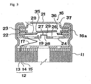
- Fig. 2 and Fig. 3 shows a condition in which the electric communication is interrupted by releasing the second flat contacting surface 29 and the first flat contacting surface 27, respectively.
- a side surface of the protrusion 28 is torn so as to be broken as shown in Figs. 7 and 8.
- a wall portion of the side surface of the protrusion 28 may be partly thinner so that the thinner wall portion can be easily tom by rising the shield plate 20 so as to interrupt the electric communication.
- valve layers 35 and 36 have not been broken so that gas harmful against a human body can be prevented from flowing to the exterior of the battery and an environment can be prevented from being contaminated.
- the safety device for a closed battery accomplishes the electric isolation and discharging of gas to the exterior of the battery so as to avoid exploding of the closed battery securely.
- the gas is discharged to the exterior in an emergency case.
- a baneful influence to a human body and an environment can be controlled to be as small as possible.
- the PTC thermister element 23 in a circular plate shape is provided between the shield plate 20 and the sealing plate 21 so that the thermister element 23 can act to lower electric current when a temperature of the safety device of the closed battery is increased by producing gas. Thus, an explosion caused by excess current can be prevented.
- the number of the grooves may be three and more (without regard to even number or odd number).
- a closed battery when normal electric current flows, a closed battery can be operated normally by contacting a pressure plate and a shield plate in a sealed space in a pressure-tight condition.
- a second flat contacting surface formed at a central portion of a plurality of circular grooves coaxially arranged is quickly released from a first flat contacting surface formed on a protrusion at a central portion of a pressure plate by utilizing the pressure of gas so as to interrupt an electric communication between the pressure plate and the shield plate rapidly.
- a valve layer is quickly broken so as to discharge the gas.
- an electric isolation and discharging the gas to an exterior of the battery can be performed in order to avoid exploding of the closed battery. Baneful influences against a human body and an environment can be controlled to be as small as possible since a discharge of the gas to the exterior of the battery is in an emergency case.
- cladding a metallic foil piece on a metallic substrate on which inner- and outer- circular grooves are formed is provided so that a shield plate with a valve layer securely actuated by the predetermined layer break pressure can be manufactured economically.
- a safety device for a closed battery By providing a safety device for a closed battery according to the present invention, a high safety closed battery with high performance can be manufactured economically.
Landscapes
- Chemical & Material Sciences (AREA)
- Chemical Kinetics & Catalysis (AREA)
- Electrochemistry (AREA)
- General Chemical & Material Sciences (AREA)
- Engineering & Computer Science (AREA)
- Manufacturing & Machinery (AREA)
- Gas Exhaust Devices For Batteries (AREA)
- Connection Of Batteries Or Terminals (AREA)
- Sealing Battery Cases Or Jackets (AREA)
Abstract
Description
- The present invention relates to a safety device for explosion-proof of a closed battery and a closed battery with the safety device.
- Recently, a lithium battery with non-water electrolytic solution and a secondary battery with non-water electrolytic solution for a lithium ion battery have been broadly employed for pocket electronic tools.
- Although the secondary battery has a high electro motive force, the secondary battery would explode in case of an increased inner pressure caused by chemical reaction in an electrode member with a positive electrode and a negative electrode installed in an outer container. For example, when a non-water electrolytic solution battery such as a lithium secondary battery is in an overcharge condition or a large amount of electric current is flown into the battery in a short circuit condition caused by a wrong operation, non-water electrolytic solution is solved in the electrode member and gas is produced. When the gas is continuously produced in the outer container and an inner pressure of the outer container increases, the battery would explode in finally.
- In order to avoid such an explosion, a closed battery for pocket electronic tools was developed as shown in JP-A-6-338305.
- In the conventional art, a positive electrode lid provided at an edge of an outer container comprises a porous metallic plate effected as the innermost lid and connected to a positive electrode of an electrode member through a positive electrode lead, a metallic explosion-proof valve effected as an intermediate lid electrically connected to the porous metallic plate through a central adhered portion, and a metallic cap terminal electrically connected to the metallic explosion-proof valve.
- In a structure as described above, when the inner pressure of the battery increases, the porous metallic plate and the metallic explosion-proof valve are electrically isolated by breaking the central adhered portion and gas produced in the inside of the battery is discharged by breaking a part of the metallic explosion-proof valve so as to avoid an explosion of the battery.
- However, in a conventional closed battery, some drawbacks to be solved remain. Although a central adhered portion is formed by welding a central portion of a porous metallic plate and a metallic explosion-proof valve in accordance with a spot welding method, it is difficult to weld all the portions uniformly by the spot welding method, and a welding strength of each closed battery is not constant. As a result, an inner pressure of a battery needed for isolating a communication between the porous metallic plate and the metallic explosion-proof valve is not constant. In case of the closed battery, although the inner pressure of the battery has risen to a predetermined isolation pressure, a communication between the porous metallic plate and the metallic explosion-proof valve cannot interrupted. Thus, reliability of a closed battery is damaged in view of safety.
- JP-A-9-199105 describes a sealed battery safety device having an intermediate lid with a thin portion provided to be deformed if an inner pressure of the battery increases.
- In order to solve the above problems, a purpose of the present invention is to provide a safety device for a closed battery in which a pressure plate and a shield plate can be isolated and a safety of the closed battery can be maintained even if an inner pressure of the battery exceeds a predetermined level, and a closed battery with the safety device.
- To accomplish the above purpose, a safety device of a closed battery according to the present invention comprises a positive electrode lid attached at one end of an outer container, said positive electrode lid including a pressure plate effected as the innermost lid and electrically connected to a positive electrode of an electrode member through a positive electrode lead, a shield plate effected as an intermediate lid and electrically connected to said pressure plate through a central contacting portion, and a sealing plate effected as the outermost lid and electrically connected to said shield plate wherein at least one gas flow hole is provided at said pressure plate so as to communicate an internal space of said outer container with a contacting space between said pressure plate and said shield plate a central contacting portion includes a protrusion protrud from a central portion of said pressure plate toward said shield plate and having a first flat contacting surface and a second contacting surface provided at a central portion of said shield plate and contacting with said first flat contacting surface of said protrusion, and said pressure plate and said shield plate are electrically isolated when the inner pressure level of said outer container exceeds a predetermined electric current isolation pressure.
- A safety device according to the present invention comprises a positive electrode lid attached at one end of an outer container, said positive electrode lid including a pressure plate effected as the innermost lid and electrically connected to a positive electrode of an electrode member through a positive electrode lead, a shield plate effected as an intermediate lid and electrically connected to said pressure plate through a central contacting portion, and a sealing plate effected as the outermost lid and electrically connected to said shield plate, wherein at least one gas flow hole is provided at said pressure plate so as to communicate an internal portion of said outer container with a contacting space between said pressure plate and said shield plate, a plurality of circular grooves are coaxially formed at a substantially central portion of said shield plate except connecting tab portions alternatively arranged with an angle of 180 ° so as to oppose the adjacent grooves each other; a diameter of said grooves is gradually increasing from an inner side to an outer side and said pressure plate and said shield plate are electrically isolated when an inner pressure level of said outer container exceeds a predetermined electric current isolation pressure.
- A safety device according to the present invention comprises a positive electrode lid attached at one end of an outer container, said positive electrode lid including a pressure plate effected as the innermost lid and electrically connected to a positive electrode of a electrode member through a positive electrode lead, a shield plate effected as an intermediate lid and electrically connected to said pressure plate through a central contacting portion, and a sealing plate effected as the outermost lid and electrically connected to said shield plate wherein at last one gas flow hole is provided at said pressure plate so as to communicate an internal space of said outer container with a contacting space between said pressure plate and said shield plate, said central contacting portion includes a protrusion protruding from a central portion of said pressure plate toward said shield plate and having a first flat contacting surface, and a second contacting surface provided at a central portion of said shield plate and contacting with said first flat contacting surface of said protrusion, a plurality of circular grooves are provided coaxially at a portion surrounding said second flat contacting surface of said shield plate except connecting tab portions alternatively arranged with an angle of 180° so as to oppose the adjacent grooves each other, a diameter of said grooves is gradually increasing from an inner side to an outer side, and a valve layer is formed at each of said circular grooves by adhering a metallic foil piece on a side surface of said shield plate confronting with said pressure plate and, when an inner pressure level of said outer container exceeds a predetermined electric isolation pressure, said second flat contacting surface of said shield plate is released or detached from said first flat contacting surface of said pressure plate so as to isolate an electric communication between said pressure plate and said shield plate and, when said pressure level of said outer container exceeds a predetermined layer break pressure, said valve layer is broken. It is preferable that the shield plate and the metallic foil piece are made of a clad metal pilate.
- In the safety device, it is preferable that a circular shaped PTC thermister element is provided between the shield plate and the sealing plate.
- According to the present invention, a closed battery comprises the above described safety device.
- Accordingly, in a normal condition, an electric communication between the pressure plate and the shield plate in a closed space is securely maintained by contacting the first flat contacting surface provided on the protrusion of the pressure plate and the second flat contacting surface of the shield plate. On the other hand, when the inner pressure of the battery rises rapidly and exceeds a predetermined electric current isolation pressure, the shield plate, particularly the second flat contacting surface of the shield plate is released or detached from the first flat contacting surface by producing gas so as to interrupt the electric communication between the pressure plate and the shield plate. Thus, the production of further gas being discharged to an exterior of the battery can be prevented. In such a case, the second flat contacting surface is provided at a central portion of a plurality of circular grooves coaxially and alternatively arranged with an angle of 180, so that the second flat contacting surface can be released from the first contacting surface quickly. Thus, the electric communication between the pressure plate and the shield plate can be quickly interrupted by providing the predetermined electric current isolation pressure. In such a case, the second flat contacting surface is plastically deformed so that the second flat contacting surface is avoided to contact the first flat contacting surface again. If even numbers of circular grooves are formed, the second flat contacting surface can be removed from the first flat contacting surface while both surfaces are maintained in a parallel relation.
- Although the electric isolation as described above is performed, if the chemical reaction in the outer container continues and further gas is produced and the inner pressure is further increased and exceeds a predetermined layer break pressure, the gas can be discharged to an exterior of the battery through at least one gas flow hole formed at the pressure plate, the contacting space, at least one circular groove (valve layer) and at least one gas discharging hole by breaking the circular groove (valve layer) formed at the shield plate.
- In such a case, the predetermined electric current isolation pressure is preferably 4 to 5 kg/cm2 and the predetermined layer breaking pressure is preferably 20 kg/cm2.
- The above described closed battery has the following characteristics:
- ① A shield plate and a metallic foil piece may be made of a cladding metal plate for cladding the both. A valve layer may be formed by a portion of the metallic foil piece covering an inner circular groove and an outer circular groove. The thickness of the metal plate is preferably about 50 µm and the thickness of the metallic foil piece is preferably 10 µm.
For example, as disclosed in JP-A-1-224184 filed by the present inventors, such a clad metal plate is manufactured by a glow discharge method in which a grounded metallic substrate having a contacting surface and a grounded metallic foil piece are effected as one electrode A and the other electrode B supported by an insulator are applied with alternative current 1 to 50 MHz in inactive gas under extreme low pressure of 1 x 10⁻¹ to 1 x 10⁻⁴ Torr. An area of the electrode A exposed with plasma caused by the glow discharge is one third less than an area of the electrode B and etched by a sputter etching method. - ② It is preferable that a circular shaped PTC thermister element is provided between a shield plate and a sealing plate. The PTC thermister element controls and reduces electric current while the temperature of a closed battery is increasing so as to avoid exploding caused by excess current.
-
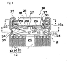
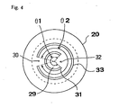
- Fig. 1 shows a structure of an embodiment of a safety device of a closed battery according to the present invention in a normal operation condition. Fig. 2 shows a structure of the embodiment of the safety device of the closed battery according to the present invention in a condition in which a pressure plate and a shield plate are detached to shut down an electric communication. Fig. 3 shows a structure of the.embodiment of the safety device of the closed battery according to the present invention in a condition in which a valve layer is broken. Fig. 4 shows a perspective view taken along a line B-B in Fig. 1. Fig. 5 shows a perspective view taken along a line A-A in Fig. 1. Fig. 6 shows a mechanism in which a first central contact portion of the pressure plate is released from a second central contacting portion of the shield plate in a parallel relation.
- Fig. 7 shows a structure of another embodiment of a safety device of a closed battery according to the present invention in which a pressure plate and a shield plate is electrically isolated. Fig. 8 shows a structure of another embodiment of the safety device of the closed battery according to the present invention in which a valve layer is broken.
- Embodiments according to the present invention will be described in detail with reference to the accompanying drawings.
- A structure of an embodiment of a safety device of a closed battery according to the present invention is explained with reference to Fig. 1 to Fig. 3.
- As shown in Fig. 1 to Fig. 3, an
electrode member 12 is installed in anouter container 11 used as a negative terminal. A positive electrode, aseparator 14 and anegative electrode 15 are laminated as the electrode and formed into a roll. A safety device of a closed battery used for both an explosion-proof and a terminal is provided at an upper opening portion of theouter container 11. The safety device is actually constituted by apositive electrode lid 16 caulked at the upper opening portion of theouter container 11 through anisolate gasket 16a. - As shown in Fig. 1 to Fig. 3, the
positive electrode lid 16 comprises apressure plate 18 actually effected as the innermost lid and connected to thepositive electrode 13 of theelectrode member 12 through apositive electrode lead 17, ashield plate 20 effected as an intermediate lid and electrically connected to thepressure plate 18 through acentral contact portion 19 and asealing plate 21 effected as an outermost lid and electrically connected to theshield plate 20. Thepositive electrode lid 16 comprises acircular isolating plate 22 sandwiched between thepressure plate 18 and theshield plate 20, and a circularPTC thermister element 23 sandwiched between theshield plate 20 and thesealing plate 21. - A structure of the
positive electrode lid 16 as described above is explained. - As shown in Fig. 1 to Fig. 3 and Fig. 5, the
pressure plate 18 has a plurality ofgas flow holes 24. Aninternal space 25 of the outer container is connected to a contactingspace 26 located between thepressure plate 18 and theshield plate 20 through thegas flow holes 24. - As shown in Fig. 1 to Fig. 3, the
central contact portion 19 electrically connecting thepressure plate 18 and theshield plate 20 is constituted by aprotrusion 28 having a firstflat contact surface 27 and protruding from a central portion toward theshield plate 20, and a secondflat contact surface 29 located at the central portion of theshield plate 20 and contacting the first flat surface of theprotrusion 28. - As shown in Fig. 1 to Fig. 4, at a portion surrounding the second
flat contact surface 29 of theshield plate 20, an innercircular groove 31 having a horse shoe shape is formed except a portion for a first connectingtab portion 30. On the other hand, at a portion surrounding the innercircular groove 31, an outercircular groove 33 having a horse shoe shape and the diameter of which is larger than that of the innercircular groove 31, is formed except a portion of a second connectingtab 32 opposing the first connectingtab portion 30 at an angle of 180°. Therein, it is preferable that an angle of circumference θ 1 of the innercircular groove 31 is smaller than an angle of circumference θ 2 of the outercircular groove 33. The angle θ 1 is preferably larger than the angle of the first connectingtab 30. - The horseshoe shaped inner
circular groove 31 and outercircular groove 33 may be formed along a circle line, an oval line, other undefined circles and an outline of polygons. - In the embodiment according to the present invention, as shown in Fig. 1 to Fig. 3, a
metallic foil piece 34 is attached on a surface of theshield plate 20 at a side confronting thepressure plate 18. Valve layers 35 and 36 are formed by the covering the innercircular groove 31 and the outercircular groove 33 with themetallic foil 34, respectively. The valve layers 35 and 36 are designed to be broken when a pressure exceeding the predetermined rupture pressure (for example, 20 kg/cm2) is applied to the valve layers 35 and 36. When a clad metal plate is formed by cladding ametallic foil piece 34 on theshield plate 20 made of an aluminum metal substrate with a thickness (i.e., 50 µ m), a copper foil piece having a thickness of 10 µ m may be used as themetallic foil 34. - In the present invention, the valve films for covering the inner circular groove and the outer circular groove with a metallic foil piece by adhering the
metallic foil piece 34 on the surface of theshield plate 20 confronting the pressure plate as described above are not essential. Instead of the innercircular groove 31 and the outercircular groove 33 penetrating into theshield plate 20, notches having a V-shaped cross section may be formed at a part of theshield plate 20 by score processing along a thickness direction. When such a score is formed, adhering a metallic foil piece is unnecessary at a side of theshield plate 20 confronting the pressure plate, since a groove having a thinner wall is provided. - In a relation between the central contacting
portion 19 and theshield plate 20 as described above, when the inner pressure of the outer container is increased and exceeds a predetermined electric isolation pressure, while thevalve film 36 is plastically deformed as shown in Fig. 3 and Fig. 6, a portion of theshield plate 20 inside of the outercircular groove 33 wholly inclines along one direction so as to form an inclined surface a. On the other hand, the secondflat surface 29 deforms thevalve layer 35 by simultaneously inclining along an opposite direction with respect to the inclined surface a. As the result, the secondflat contact surface 29 is released in parallel with respect to the first flat contactingsurface 27 formed by theprotrusion 28 of thepressure plate 18. When the pressure of gas reaches a predetermined electric isolation pressure, theshield plate 20 can be released from thepressure plate 18 by providing the inner and outercircular grooves surface 29 is released in parallel with respect to the first contactingsurface 27. Even if a central portion of theshield plate 20 is slightly risen, theshield plate 20 is completely released from thepressure plate 18. Thus, an electric communication between thepressure plate 18 and theshield plate 20 can be interrupted quickly. - Fig. 2 and Fig. 3 shows a condition in which the electric communication is interrupted by releasing the second flat contacting
surface 29 and the first flat contactingsurface 27, respectively. When the second flat contactingsurface 29 and the first flat contactingsurface 27 are adhered (for example, welded), a side surface of theprotrusion 28 is torn so as to be broken as shown in Figs. 7 and 8. In order to break the side surface of theprotrusion 28, a wall portion of the side surface of theprotrusion 28 may be partly thinner so that the thinner wall portion can be easily tom by rising theshield plate 20 so as to interrupt the electric communication. - In the following, an operation of the safety device of the closed battery as described above is described with reference to Fig. 1 to Fig. 3.
- In the closed battery, if a large amount of electric current is flown in an overcharge condition, highly corrosive gas is produced in the
outer container 11 by flowing a large amount of the electric current and the pressure in theouter container 11 is increased. If this condition is maintained, the closed battery would explode. However, in the embodiment, when the pressure of the gas in theouter container 11 exceeds the predetermined electric isolation pressure, the gas is introduced into the contactingspace 26 and then the second flat contactingsurface 29 of theshield plate 20 is quickly released from the first flat contactingsurface 27 formed on theprotrusion 28 of thepressure plate 20 so as to interrupt the electric communication between thepressure plate 18 and theshield plate 20. Accordingly, it is prevented that further gas is produced so that an explosion of theouter container 11 caused by the increased inner pressure of theouter container 11 can be avoided securely. In addition, the valve layers 35 and 36 have not been broken so that gas harmful against a human body can be prevented from flowing to the exterior of the battery and an environment can be prevented from being contaminated. - Even if the chemical reaction is still proceeding in the
outer container 11, the inner pressure exceeds the predetermined layer breaking pressure due to the production of gas although the electric communication is interrupted, and one or both of the valve layers 35 and 36 would break as shown in Fig. 3 so that the gas can be quickly discharged to the exterior from the contactingspace 26 through a space between theshield plate 20 and the sealingplate 21 and the gas flow holes 37 so as to avoid for exploding of the closed battery securely. - As described above, the safety device for a closed battery according to the present invention accomplishes the electric isolation and discharging of gas to the exterior of the battery so as to avoid exploding of the closed battery securely. The gas is discharged to the exterior in an emergency case. Thus, a baneful influence to a human body and an environment can be controlled to be as small as possible.
- As shown in Fig. 1 to Fig. 3, in the embodiment according to the present invention, the
PTC thermister element 23 in a circular plate shape is provided between theshield plate 20 and the sealingplate 21 so that thethermister element 23 can act to lower electric current when a temperature of the safety device of the closed battery is increased by producing gas. Thus, an explosion caused by excess current can be prevented. - In the embodiment according to the present invention as described above, although two
circular grooves surface 29, the number of the grooves may be three and more (without regard to even number or odd number). - As described above, in the safety device of the closed battery according to the present invention, when normal electric current flows, a closed battery can be operated normally by contacting a pressure plate and a shield plate in a sealed space in a pressure-tight condition. When an excess current flows, a second flat contacting surface formed at a central portion of a plurality of circular grooves coaxially arranged is quickly released from a first flat contacting surface formed on a protrusion at a central portion of a pressure plate by utilizing the pressure of gas so as to interrupt an electric communication between the pressure plate and the shield plate rapidly. In addition, when the gas is further produced, a valve layer is quickly broken so as to discharge the gas. Thus, an electric isolation and discharging the gas to an exterior of the battery can be performed in order to avoid exploding of the closed battery. Baneful influences against a human body and an environment can be controlled to be as small as possible since a discharge of the gas to the exterior of the battery is in an emergency case.
- In the safety device for a closed battery according to the present invention, cladding a metallic foil piece on a metallic substrate on which inner- and outer- circular grooves are formed is provided so that a shield plate with a valve layer securely actuated by the predetermined layer break pressure can be manufactured economically.
- In addition, by providing a PTC thermister element in a circular shape between a shield plate and a sealing plate, the electric current is controlled to be reduced. Thereby, an explosion caused by an excess current can also be prevented.
- By providing a safety device for a closed battery according to the present invention, a high safety closed battery with high performance can be manufactured economically.
Claims (6)
- A safety device of a closed battery comprising a positive electrode lid (16) attached at one end of an outer container (11), said positive electrode lid (16) including:a pressure plate (18) effected as innermost lid and electrically connected to a positive electrode (13) of an electrode member (12) through a positive electrode lead (17),a shield plate (20) comprising a plurality of grooves (31, 33) which are covered by a metallic foil (34), said shield plate (20) is effected as an intermediate lid and electrically connected to said pressure plate (18) through a central contacting portion (19), anda sealing plate (21) effected as the outermost lid and electrically connected to the shield plate (20),wherein at least one gas flow hole (24) is provided at said pressure plate (18) so as to communicate an internal space (25) of said outer container (11) with the contacting space (26) between said pressure plate (18) and the shield plate (20),
said central contacting portion (19) includes a protrusion (28) protruding from a central portion of said pressure plate (18) toward said shield plate (20) and having a first flat contacting surface (27), and a second contacting surface (29) provided at a central portion of said shield plate (20) and contacting with the first flat contacting surface (27) of said protrusion (28) and
said pressure plate (18) and said shield plate (20) are electrically isolated when an inner pressure level of said outer container (11) exceeds a predetermined electric current isolation pressure. - A safety device according to claim 1, wherein
a plurality of circular grooves (31, 33) are coaxially formed at a substantially central portion of said shield plate (20) except connecting tap portions (30,32) alternatively arranged with an angle of 180° so as to oppose the adjacent grooves (31, 33) each other,
a diameter of said grooves (31, 33) is gradually increasing from an inner side to an outer side and
said pressure plate (18) and said shield plate (20) are electrically isolated when an inner pressure level of said outer container (11) exceeds a predetermined electric current isolation pressure. - A safety device according to claim 1 or 2, wherein
a plurality of circular grooves (31, 33) are provided coaxially at a portion surrounding said second flat contacting surface (29) of said shield plate (20) except connecting tap portions (30, 32) alternatively arranged with an angle of 180° so as to oppose the adjacent grooves (31, 33) each other,
a diameter of said grooves (31, 33) is gradually increasing from an inner side to an outer side, and
a valve layer (35, 36) is formed at each of said circular grooves (31, 33) by adhering a metallic foil piece (34) on a side surface of said shield plate (20) confronting with said pressure plate (18), and
when an inner pressure level of said outer container (11) exceeds a predetermined electric isolation pressure, said second flat contacting surface (29) of said shield plate (20) is released from said first flat contacting surface (27) of said pressure plate (18) so as to isolate an electric communication between the pressure plate (18) and said shield plate (20) and
when said pressure level of said outer container (11) exceeds a predetermined layer break pressure, each of said valve layers (35, 36) is broken. - A safety device according to any one of claims 1 to 3, wherein said shield plate (20) and said metallic foil piece (34) are formed by clad metallic plates, respectively.
- A safety device according to any one of claims 1 to 4, wherein a PTC thermister element (23) in a circular shape is provided between the shield plate (20) and said sealing plate (21).
- A closed battery comprising a safety device recited in any one of claims 1 to 5.
Applications Claiming Priority (3)
| Application Number | Priority Date | Filing Date | Title |
|---|---|---|---|
| JP32907198 | 1998-11-19 | ||
| JP32907198 | 1998-11-19 | ||
| PCT/JP1999/006495 WO2000031810A1 (en) | 1998-11-19 | 1999-11-19 | Safety device for sealed battery and sealed battery using it |
Publications (3)
| Publication Number | Publication Date |
|---|---|
| EP1134818A1 EP1134818A1 (en) | 2001-09-19 |
| EP1134818A4 EP1134818A4 (en) | 2004-09-08 |
| EP1134818B1 true EP1134818B1 (en) | 2007-01-17 |
Family
ID=18217301
Family Applications (1)
| Application Number | Title | Priority Date | Filing Date |
|---|---|---|---|
| EP99972790A Expired - Lifetime EP1134818B1 (en) | 1998-11-19 | 1999-11-19 | Safety device for sealed battery and sealed battery using it |
Country Status (9)
| Country | Link |
|---|---|
| US (1) | US6632559B1 (en) |
| EP (1) | EP1134818B1 (en) |
| KR (1) | KR100636589B1 (en) |
| CN (1) | CN1187847C (en) |
| AU (1) | AU1185200A (en) |
| DE (1) | DE69934904T2 (en) |
| MY (1) | MY123287A (en) |
| TW (1) | TW472411B (en) |
| WO (1) | WO2000031810A1 (en) |
Families Citing this family (25)
| Publication number | Priority date | Publication date | Assignee | Title |
|---|---|---|---|---|
| JP4608719B2 (en) * | 2000-01-14 | 2011-01-12 | ソニー株式会社 | Non-aqueous electrolyte secondary battery |
| JP2004247059A (en) * | 2003-02-10 | 2004-09-02 | Toyota Motor Corp | Lithium ion secondary battery |
| JP4590856B2 (en) * | 2003-11-14 | 2010-12-01 | 新神戸電機株式会社 | Sealed battery |
| KR100578805B1 (en) * | 2004-03-24 | 2006-05-11 | 삼성에스디아이 주식회사 | Cap assembly and secondary battery having the same |
| KR101253380B1 (en) * | 2005-05-16 | 2013-04-11 | 타이코 일렉트로닉스 레이켐 케이. 케이. | Sealing body and cell pack using the same |
| JP2007012803A (en) * | 2005-06-29 | 2007-01-18 | Sanyo Electric Co Ltd | Electrochemical element |
| KR20080072443A (en) * | 2007-02-02 | 2008-08-06 | 삼성에스디아이 주식회사 | Welding fixing cap and battery module having same |
| US7851077B2 (en) | 2007-03-13 | 2010-12-14 | Dell Products L.P. | System and method for enhanced information handling system battery safety |
| KR100882916B1 (en) | 2007-08-27 | 2009-02-10 | 삼성에스디아이 주식회사 | Secondary battery |
| KR100922351B1 (en) * | 2007-10-02 | 2009-10-21 | 삼성에스디아이 주식회사 | Secondary battery |
| US8486546B2 (en) | 2008-12-01 | 2013-07-16 | Samsung Sdi Co., Ltd. | Cap assembly and secondary battery using the same with notched vent member |
| KR20100065670A (en) | 2008-12-08 | 2010-06-17 | 삼성에스디아이 주식회사 | Rechargeable battery |
| KR101086359B1 (en) | 2008-12-10 | 2011-11-23 | 삼성에스디아이 주식회사 | Cap assembly for secondary battery and secondary battery using same |
| KR101050535B1 (en) | 2008-12-18 | 2011-07-20 | 삼성에스디아이 주식회사 | Cap assembly and secondary battery having the same |
| US8241772B2 (en) | 2009-06-12 | 2012-08-14 | Tesla Motors, Inc. | Integrated battery pressure relief and terminal isolation system |
| CN105074960B (en) * | 2013-04-16 | 2018-01-09 | 株式会社早出长野 | Battery container |
| KR101826879B1 (en) | 2013-11-04 | 2018-02-07 | 주식회사 엘지화학 | Current interrupting device and Secondary battery using the same |
| JP5910624B2 (en) * | 2013-12-26 | 2016-04-27 | 株式会社豊田自動織機 | Battery pack |
| CN105140446B (en) * | 2015-08-17 | 2017-07-28 | 汕头市毅和电源科技有限公司 | Explosion-proof device of lithium battery |
| KR200493141Y1 (en) * | 2016-04-11 | 2021-02-05 | 비메드 테크니크 알레틀러 사나이 베 티카렛 에이.에스. | Pressure balancing apparatus |
| US20210203047A1 (en) * | 2017-10-23 | 2021-07-01 | Sanyo Electric Co., Ltd. | Cylindrical batteries |
| CN112968258B (en) * | 2018-04-23 | 2022-10-18 | 比亚迪股份有限公司 | Battery cover assemblies, batteries, battery modules, power cells and electric vehicles |
| DE102020131594A1 (en) * | 2020-11-30 | 2022-06-02 | Mann+Hummel Gmbh | Pressure equalization device and method for pressure equalization |
| CN113241499B (en) * | 2021-05-10 | 2023-09-19 | 宁德新能源科技有限公司 | Electrochemical devices and electronic equipment |
| EP4564540A1 (en) * | 2023-12-01 | 2025-06-04 | Automotive Cells Company SE | Energy storage cell comprising a precut venting membrane |
Family Cites Families (8)
| Publication number | Priority date | Publication date | Assignee | Title |
|---|---|---|---|---|
| JP3233679B2 (en) * | 1992-05-14 | 2001-11-26 | 旭化成株式会社 | Manufacturing method of battery safety valve device |
| JPH06333548A (en) * | 1993-05-19 | 1994-12-02 | Matsushita Electric Ind Co Ltd | Explosion-proof battery |
| CA2240415C (en) * | 1995-10-31 | 2002-12-24 | Matsushita Electric Industrial Co., Ltd. | Explosion-proof seal plate for sealed type cell and production method thereof |
| JPH09199105A (en) * | 1996-01-19 | 1997-07-31 | Matsushita Electric Ind Co Ltd | Explosion-proof sealing plate for secondary battery |
| KR100386394B1 (en) * | 1996-02-16 | 2003-08-14 | 후지 덴키 가가쿠 가부시키가이샤 | Battery with explosion-proof function |
| EP0849815B1 (en) * | 1996-07-09 | 2005-05-04 | Matsushita Electric Industrial Co., Ltd. | Secondary cell with assembly sealing plate |
| MY124164A (en) * | 1997-05-09 | 2006-06-30 | Fukuda Metal Foil Powder | Closed battery and closing member |
| KR100277655B1 (en) * | 1998-09-22 | 2001-02-01 | 김순택 | Cap assembly of secondary battery and method for making the same |
-
1999
- 1999-11-18 MY MYPI99005043A patent/MY123287A/en unknown
- 1999-11-18 TW TW088120191A patent/TW472411B/en not_active IP Right Cessation
- 1999-11-19 KR KR1020017006323A patent/KR100636589B1/en not_active Expired - Fee Related
- 1999-11-19 US US09/856,047 patent/US6632559B1/en not_active Expired - Fee Related
- 1999-11-19 DE DE69934904T patent/DE69934904T2/en not_active Expired - Fee Related
- 1999-11-19 AU AU11852/00A patent/AU1185200A/en not_active Abandoned
- 1999-11-19 WO PCT/JP1999/006495 patent/WO2000031810A1/en not_active Ceased
- 1999-11-19 CN CNB998134333A patent/CN1187847C/en not_active Expired - Fee Related
- 1999-11-19 EP EP99972790A patent/EP1134818B1/en not_active Expired - Lifetime
Also Published As
| Publication number | Publication date |
|---|---|
| CN1348612A (en) | 2002-05-08 |
| AU1185200A (en) | 2000-06-13 |
| WO2000031810A1 (en) | 2000-06-02 |
| DE69934904T2 (en) | 2007-05-31 |
| EP1134818A4 (en) | 2004-09-08 |
| EP1134818A1 (en) | 2001-09-19 |
| KR100636589B1 (en) | 2006-10-19 |
| KR20010101035A (en) | 2001-11-14 |
| DE69934904D1 (en) | 2007-03-08 |
| MY123287A (en) | 2006-05-31 |
| TW472411B (en) | 2002-01-11 |
| CN1187847C (en) | 2005-02-02 |
| US6632559B1 (en) | 2003-10-14 |
Similar Documents
| Publication | Publication Date | Title |
|---|---|---|
| EP1134818B1 (en) | Safety device for sealed battery and sealed battery using it | |
| EP1458038B1 (en) | Explosion-proof seal plate for sealed type cell and production method thereof | |
| EP2380226B1 (en) | Modular cid assembly for a lithium ion battery | |
| CN100411235C (en) | rechargeable battery | |
| JP2010238672A (en) | Secondary battery | |
| JP2006012831A (en) | Secondary battery, secondary battery cap assembly, and secondary battery safety valve mounting method | |
| KR100525533B1 (en) | Explosion-proof valve group and hermetically closed secondary battery made by using the same | |
| EP4254579A1 (en) | Secondary battery | |
| CA2318183C (en) | Enclosed cell and sealer | |
| JP2000082457A (en) | Electric/electronic equipment and part safeguard, sealed battery safeguard using it and sealed battery using it | |
| EP2384519A1 (en) | Modular cid assembly for a lithium ion battery | |
| KR20040110156A (en) | Pouch type secondary battery with safty vent | |
| KR20030032540A (en) | Safety valve device and secondary battery applying such | |
| US6303246B1 (en) | Hermetically sealed cell and sealing body | |
| JP3983050B2 (en) | Sealed battery safety device and sealed battery using the same | |
| KR100889765B1 (en) | Lithium ion polymer battery | |
| KR20010045030A (en) | Sealed battery | |
| JP3322566B2 (en) | Explosion-proof sealing plate for sealed batteries | |
| JPWO2001011701A1 (en) | Safety device for sealed battery and sealed battery using the same | |
| KR20020021887A (en) | Safety apparatus used in secondary battery | |
| JP2001102038A (en) | Safety device for sealed battery and lead mounting plate in the device | |
| KR20040043041A (en) | Secondary battery with safety device | |
| JPH11238494A (en) | Sealing device for sealed batteries | |
| JP2002117823A (en) | Safety device for sealed battery and sealed battery using the same | |
| KR20170075658A (en) | CID assembly for a secondary battery with excellent durability |
Legal Events
| Date | Code | Title | Description |
|---|---|---|---|
| PUAI | Public reference made under article 153(3) epc to a published international application that has entered the european phase |
Free format text: ORIGINAL CODE: 0009012 |
|
| 17P | Request for examination filed |
Effective date: 20010601 |
|
| AK | Designated contracting states |
Kind code of ref document: A1 Designated state(s): AT BE CH CY DE DK ES FI FR GB GR IE IT LI LU MC NL PT SE |
|
| AX | Request for extension of the european patent |
Free format text: AL;LT;LV;MK;RO;SI |
|
| RBV | Designated contracting states (corrected) |
Designated state(s): BE DE FR GB IT NL |
|
| A4 | Supplementary search report drawn up and despatched |
Effective date: 20040727 |
|
| 17Q | First examination report despatched |
Effective date: 20041214 |
|
| GRAP | Despatch of communication of intention to grant a patent |
Free format text: ORIGINAL CODE: EPIDOSNIGR1 |
|
| GRAS | Grant fee paid |
Free format text: ORIGINAL CODE: EPIDOSNIGR3 |
|
| GRAA | (expected) grant |
Free format text: ORIGINAL CODE: 0009210 |
|
| AK | Designated contracting states |
Kind code of ref document: B1 Designated state(s): BE DE FR GB IT NL |
|
| REG | Reference to a national code |
Ref country code: GB Ref legal event code: FG4D |
|
| REF | Corresponds to: |
Ref document number: 69934904 Country of ref document: DE Date of ref document: 20070308 Kind code of ref document: P |
|
| ET | Fr: translation filed | ||
| PLBE | No opposition filed within time limit |
Free format text: ORIGINAL CODE: 0009261 |
|
| STAA | Information on the status of an ep patent application or granted ep patent |
Free format text: STATUS: NO OPPOSITION FILED WITHIN TIME LIMIT |
|
| 26N | No opposition filed |
Effective date: 20071018 |
|
| PGFP | Annual fee paid to national office [announced via postgrant information from national office to epo] |
Ref country code: NL Payment date: 20071128 Year of fee payment: 9 |
|
| PGFP | Annual fee paid to national office [announced via postgrant information from national office to epo] |
Ref country code: IT Payment date: 20071121 Year of fee payment: 9 |
|
| PGFP | Annual fee paid to national office [announced via postgrant information from national office to epo] |
Ref country code: BE Payment date: 20071127 Year of fee payment: 9 |
|
| PGFP | Annual fee paid to national office [announced via postgrant information from national office to epo] |
Ref country code: GB Payment date: 20071122 Year of fee payment: 9 Ref country code: FR Payment date: 20071116 Year of fee payment: 9 |
|
| PGFP | Annual fee paid to national office [announced via postgrant information from national office to epo] |
Ref country code: DE Payment date: 20071228 Year of fee payment: 9 |
|
| BERE | Be: lapsed |
Owner name: TOYO KOHAN CO., LTD. Effective date: 20081130 |
|
| GBPC | Gb: european patent ceased through non-payment of renewal fee |
Effective date: 20081119 |
|
| PG25 | Lapsed in a contracting state [announced via postgrant information from national office to epo] |
Ref country code: NL Free format text: LAPSE BECAUSE OF NON-PAYMENT OF DUE FEES Effective date: 20090601 |
|
| NLV4 | Nl: lapsed or anulled due to non-payment of the annual fee |
Effective date: 20090601 |
|
| PG25 | Lapsed in a contracting state [announced via postgrant information from national office to epo] |
Ref country code: IT Free format text: LAPSE BECAUSE OF NON-PAYMENT OF DUE FEES Effective date: 20081119 |
|
| REG | Reference to a national code |
Ref country code: FR Ref legal event code: ST Effective date: 20090731 |
|
| PG25 | Lapsed in a contracting state [announced via postgrant information from national office to epo] |
Ref country code: BE Free format text: LAPSE BECAUSE OF NON-PAYMENT OF DUE FEES Effective date: 20081130 |
|
| PG25 | Lapsed in a contracting state [announced via postgrant information from national office to epo] |
Ref country code: DE Free format text: LAPSE BECAUSE OF NON-PAYMENT OF DUE FEES Effective date: 20090603 |
|
| PG25 | Lapsed in a contracting state [announced via postgrant information from national office to epo] |
Ref country code: GB Free format text: LAPSE BECAUSE OF NON-PAYMENT OF DUE FEES Effective date: 20081119 |
|
| PG25 | Lapsed in a contracting state [announced via postgrant information from national office to epo] |
Ref country code: FR Free format text: LAPSE BECAUSE OF NON-PAYMENT OF DUE FEES Effective date: 20081130 |