EP1134781A2 - High-voltage discharge lamp - Google Patents
High-voltage discharge lamp Download PDFInfo
- Publication number
- EP1134781A2 EP1134781A2 EP00250452A EP00250452A EP1134781A2 EP 1134781 A2 EP1134781 A2 EP 1134781A2 EP 00250452 A EP00250452 A EP 00250452A EP 00250452 A EP00250452 A EP 00250452A EP 1134781 A2 EP1134781 A2 EP 1134781A2
- Authority
- EP
- European Patent Office
- Prior art keywords
- discharge lamp
- voltage discharge
- bulb
- molybdenum foils
- electrodes
- Prior art date
- Legal status (The legal status is an assumption and is not a legal conclusion. Google has not performed a legal analysis and makes no representation as to the accuracy of the status listed.)
- Granted
Links
Images

Classifications
-
- H—ELECTRICITY
- H01—ELECTRIC ELEMENTS
- H01J—ELECTRIC DISCHARGE TUBES OR DISCHARGE LAMPS
- H01J61/00—Gas-discharge or vapour-discharge lamps
- H01J61/02—Details
- H01J61/36—Seals between parts of vessels; Seals for leading-in conductors; Leading-in conductors
- H01J61/366—Seals for leading-in conductors
-
- H—ELECTRICITY
- H01—ELECTRIC ELEMENTS
- H01J—ELECTRIC DISCHARGE TUBES OR DISCHARGE LAMPS
- H01J5/00—Details relating to vessels or to leading-in conductors common to two or more basic types of discharge tubes or lamps
- H01J5/20—Seals between parts of vessels
- H01J5/22—Vacuum-tight joints between parts of vessel
- H01J5/26—Vacuum-tight joints between parts of vessel between insulating and conductive parts of vessel
-
- H—ELECTRICITY
- H01—ELECTRIC ELEMENTS
- H01J—ELECTRIC DISCHARGE TUBES OR DISCHARGE LAMPS
- H01J61/00—Gas-discharge or vapour-discharge lamps
- H01J61/02—Details
- H01J61/36—Seals between parts of vessels; Seals for leading-in conductors; Leading-in conductors
Definitions
- This invention relates to a high-voltage discharge lamp and, more particularly, to a high-voltage discharge lamp in which it is possible to prevent a quartz-glass bulb from bursting at the time of high-temperature thermal processing or at the time of operation.
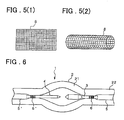
- a high-voltage discharge lamp according to the prior art has a structure of the kind shown in Fig. 6, by way of example.
- a high-voltage discharge lamp 1 includes a quartz-glass bulb 2, which comprises an enlarged portion 21 that provides a light-emitting space and a seal portion 22, and a pair of opposing electrodes (an anode 3 and cathode 4) disposed within the glass bulb 2.
- the anode 3 and cathode 4 are joined to the molybdenum foils 5 and 5', respectively, by means such as welding. Further, the molybdenum foils 5, 5' are hermetically sealed within the bulb 2 at the seal portions 22 thereof.
- the enlarged portion 21 having the light-emitting space is filled with a discharge gas or the like.
- Coils 6, 6' comprising a material such as tungsten, tantalum or molybdenum are wound on the anode 3 and cathode 4, respectively, on or near the joints between these electrodes and the molybdenum foils 5, 5'.
- an object of the present invention is to provide a high-voltage discharge lamp in which it is possible to eliminate the scratching of a quartz-glass bulb and the deformation of electrodes and to mitigate thermal stress at the time of high-temperature thermal processing and high-voltage discharge operation, as a result of which the occurrence of cracking can be prevented and sufficiently stable brightness can be obtained.
- a high-voltage discharge lamp in which the joint, as well as the vicinity thereof, between at least one electrode and molybdenum foil is covered by a cylindrical member the outer and/or inner surface of which has slits, or by a mesh-like member.
- the inventor has found that such a high-voltage discharge lamp will no longer have its quartz-glass bulb scratched, that the electrode will no longer be deformed because it is unnecessary for the joint or the vicinity thereof to have a hermetic seal, that it is possible to mitigate thermal stress at the time of high-temperature thermal processing or high-voltage discharge operation, thereby preventing the occurrence of cracking, and that sufficiently stable brightness is obtained.
- the present invention has been perfected on the basis of these findings.
- a high-voltage discharge lamp having a bulb made of quartz glass, a pair of electrodes and molybdenum foils, wherein the pair of electrodes are arranged so as to oppose each other and are joined to respective ones of the molybdenum foils, and the bulb and molybdenum foils are hermetically sealed at seal portions of the bulb, characterized in that joints, as well as the vicinities thereof, between the pair of electrodes and the molybdenum foils are covered by cylindrical members having slits on an outer surface and/or an inner surface thereof.
- a high-voltage discharge lamp having a bulb made of quartz glass, a pair of electrodes and molybdenum foils, wherein the pair of electrodes are arranged so as to oppose each other and are joined to respective ones of the molybdenum foils, and the bulb and molybdenum foils are hermetically sealed at seal portions of the bulb, characterized in that joints, as well as the vicinities thereof, between the pair of electrodes and the molybdenum foils are covered by mesh-like members.
- a bulb 2 made of quartz glass may be one obtained naturally or synthetically.
- the bulb 2 may be integrally molded or may be produced by adhering two or more layers together.
- the shape of the enlarged or bulged portion (bulb portion) 21 that provides the light-emitting space may be spherical or an ellipsoid.
- An anode 3 and cathode 4 preferably consist of tungsten, molybdenum or tantalum, with tungsten being particularly preferred. There is no particular limitation concerning the spacing between these electrodes.
- the anode 3 and cathode 4 are joined to molybdenum foils 5 and 5', respectively, by means such as welding.
- the molybdenum foils 5, 5' are hermetically sealed within the bulb 2 at the seal portions 22 thereof.
- the enlarged portion 21 having the light-emitting space is filled with a discharge gas or the like.
- Cylindrical members 7, 7' are disposed so as to cover i joints 31, 41, as well as the vicinities thereof, between the electrodes 3, 4 and the molybdenum foils 5, 5', respectively.
- the cylindrical members 7, 7' cover the joints 31, 41, respectively, and the vicinities thereof, there is no particular limitation relating to the axial lengths of the cylindrical members, the lengths of the covered portions of the electrodes and the lengths of the covered portions of the molybdenum foils.
- the cylindrical members cover the joints 31. 41 as well as the vicinities thereof. between both electrodes and both molybdenum foils.
- an arrangement 5 in which only one of the joints 31, 41 and the vicinity thereof is covered may be adopted.
- cylindrical members 7, 7' be embedded only in the seal portion 22 and not be exposed to the enlarged portion 21. Further, the cylindrical members 7, 7' need not have a hermetic seal with respect to both electrodes and molybdenum foils.
- the cylindrical members 7, 7' preferably consist of tungsten, molybdenum or tantalum, with tungsten being particularly preferred.
- the cylindrical members 7, 7' have slits 71 provided on their outer and/or inner surfaces.
- the slits 71 mitigate thermal stress at the time of high-temperature thermal processing and at operation of the high-voltage discharge lamp, thereby making it possible to prevent the occurrence of cracking.
- Figs. 2 to 4 illustrate embodiments of the cylindrical member 7 the outer surface of which is provided with the slits 71.
- the slits 71 extend axially of the cylindrical member 7 in Fig. 2, circumferentially of the cylindrical member 7 in Fig. 3 and helically of the cylindrical member 7 in Fig. 4.
- the slits may be provided both axially and circumferentially of the cylindrical member 7.
- the arrangement of Fig. 4 in which the slits 71 have the helical configuration is particularly preferred.
- the slits may be provided on the inner or outer surface of the cylindrical member or on both the inner and outer surfaces.
- the slits are provided on the inner surface, it is possible to prevent a decline in the slidability of the cylindrical member at the time of high-temperature thermal processing and at operation of the high-voltage discharge lamp. This has the effect of mitigating thermal stress.
- the slits are provided so as to extend in the axial direction (Fig. 2) or circumferential direction (Fig. 3), there is no particular limitation concerning the number of slits. If the slits are provided in the form of the helical configuration (Fig. 4), there is no particular limitation concerning the helical pitch. Further, there is no limitation concerning the width and depth of the slits. There is also no particular limitation relating to the cross-sectional shape of the slits, and the slits may e.g. be rectangular, triangular, square, semi-circular or U-shaped in cross section.
- the edge portion of the slits be worked to have an arcuate or chamfered shape.
- the cylindrical member can be manufactured through any of the usual methods.
- Fig. 5A illustrates the development on a plane, of a mesh-like member 8 that covers the joint: as well as the vicinity thereof, between an electrode and molybdenum foil
- Fig. 5B is a perspective view of the mesh-like member 8.
- the mesh-like member 8 preferably consist of tungsten, molybdenum or tantalum, with tungsten being particularly preferred.
- the mesh-like cylindrical member 8 has a periphery composed of minute frames and is devoid of projections. This means that the glass bulb 2 will not be scratched.
- the electrode Since a hermetic seal is not required between the mesh-like member 8 and the joint between the electrode and molybdenum foil and its vicinity, the electrode is not deformed.
- the mesh-like member 8 covers the joint and its vicinity, there is no particular limitation relating to the axial length of the member, the length of the covered portion of the electrode and the length of the covered portion of the molybdenum foil.
- the joints and their vicinities between both electrodes and the molybdenum foils may be covered by respective ones of mesh-like members 8 or only one of the joints and the vicinity thereof may be covered by the mesh-like member 8. It is preferred that the mesh-like member 8 be embedded only in the seal portion 22 and not be exposed to the enlarged portion 21.
- the mesh size of the mesh-like member 8 200 to 400 mesh (JIS) is preferred from the viewpoint of mitigating thermal stress at the time of high-temperature thermal processing and at the time of operation of the high-pressure discharge lamp. Further, though there is no particular limitation concerning the diameter of the wire material used as the mesh-like member, 20 to 100 ⁇ m is preferred from the viewpoint of mitigating thermal stress at the time of high-temperature thermal processing and at the time of operation of the high-pressure discharge lamp.
- the mesh-like member can be manufactured through any of the usual methods. Alternatively, a mesh-like member already available on the market can be used.
- the following example of a method of manufacture is particularly preferred: First, the joint, as well as the vicinity thereof, between an electrode and molybdenum foil is inserted into the cylindrical member or mesh-like member described above. Two of these electron and foil assemblies are formed.
- the method of inserting the prescribed portion of the electrode into the cylindrical member or mesh-like member is not particularly limited; this can be performed by a manual operation, by way of example.
- one of the above-described assemblies is placed on one seal portion of a quartz-glass bulb that has been formed into the approximate shape of a high-voltage discharge lamp, the interior is evacuated and then the seal portion is caused to contract and seal while this portion is subjected to high-temperature thermal processing.
- a light-emitting substance such as mercury is introduced from the other opening into the enlarged portion 21 for the light-emitting space, the other assembly is placed on the other seal portion, the interior is filled with an inert gas under a pressure of less than one atmosphere and the seal portion is caused to contract and seal while this portion is subjected to high-temperature thermal processing.
- the high-voltage discharge lamp of the present invention is thus manufactured. It is preferred that the enlarged portion 21 for the light-emitting space be cooled so that the substance sealed within will not vaporize.
- the high-voltage discharge lamp according to the present invention can be used in the same manner as an ordinary high-voltage discharge lamp. That is, when the high-voltage discharge lamp is connected to a power supply, a trigger voltage is applied across the cathode and anode to initiate an electrical discharge. A prescribed brightness is obtained as a result.
- the quartz-glass bulb will not be scratched, the electrodes will not be deformed and it is possible to mitigate thermal stress at the time of high-temperature thermal processing and when the high-voltage discharge lamp is operated. As a result, cracking will not occur and a sufficiently stable brightness can be obtained.
Landscapes
- Vessels And Coating Films For Discharge Lamps (AREA)
- Discharge Lamp (AREA)
Abstract
Description
Claims (8)
- A high-voltage discharge lamp comprising:a bulb made of quartz glass and having seal portions;a pair of opposing electrodes;molybdenum foils joined to respective ones of said opposing electrodes; andcylindrical members covering joints, as well as the vicinities thereof, between said molybdenum foils and respective ones of said opposing electrodes, said cylindrical members having slits formed on an outer and/or inner surface thereof;said opposing electrodes, said molybdenum foils and said cylindrical members being hermetically sealed within said bulb at the seal portions thereof.
- The high-voltage discharge lamp according to claim 1, wherein said slits are formed helically on the outer surface of said cylindrical members.
- The high-voltage discharge lamp according to claim 1 or 2, wherein said cylindrical members are made of tungsten.
- The high-voltage discharge lamp according to claim 1, wherein said slits extend longitudinally of the cylindrical members.
- The high-voltage discharge lamp according to claim 1, wherein said slits extend circumferentially of the cylindrical members.
- A high-voltage discharge lamp comprising:a bulb made of quartz glass and having seal portions;a pair of opposing electrodes;molybdenum foils joined to respective ones of said opposing electrodes; andmesh-like members covering joints, as well as the vicinities thereof, between said molybdenum foils and respective ones of said opposing electrodes;said opposing electrodes, said molybdenum foils and said mesh-like members being hermetically sealed within said bulb at the seal portions thereof.
- The high-voltage discharge lamp according to claim 6, wherein said mesh-like members are made of tungsten.
- The high-voltage discharge lamp according to claim 6 or 7, wherein said mesh-like members are substantially cylindrical.
Applications Claiming Priority (2)
| Application Number | Priority Date | Filing Date | Title |
|---|---|---|---|
| JP37729499A JP3586607B2 (en) | 1999-12-28 | 1999-12-28 | High pressure discharge lamp |
| JP37729499 | 1999-12-28 |
Publications (3)
| Publication Number | Publication Date |
|---|---|
| EP1134781A2 true EP1134781A2 (en) | 2001-09-19 |
| EP1134781A3 EP1134781A3 (en) | 2001-09-26 |
| EP1134781B1 EP1134781B1 (en) | 2006-06-21 |
Family
ID=18508579
Family Applications (1)
| Application Number | Title | Priority Date | Filing Date |
|---|---|---|---|
| EP00250452A Expired - Lifetime EP1134781B1 (en) | 1999-12-28 | 2000-12-23 | High-voltage discharge lamp |
Country Status (4)
| Country | Link |
|---|---|
| US (1) | US6426592B2 (en) |
| EP (1) | EP1134781B1 (en) |
| JP (1) | JP3586607B2 (en) |
| DE (1) | DE60028924T2 (en) |
Cited By (2)
| Publication number | Priority date | Publication date | Assignee | Title |
|---|---|---|---|---|
| EP1329942A3 (en) * | 2001-12-20 | 2006-05-03 | Nec Corporation | High-pressure discharge lamp and method of fabricating the same |
| EP1308987A3 (en) * | 2001-10-19 | 2006-05-17 | Ushiodenki Kabushiki Kaisha | Super-high pressure discharge lamp of the short arc type |
Families Citing this family (17)
| Publication number | Priority date | Publication date | Assignee | Title |
|---|---|---|---|---|
| JP3118758B2 (en) * | 1998-10-19 | 2000-12-18 | ウシオ電機株式会社 | Sealed body made of functionally graded material for lamp and lamp |
| JP3464994B2 (en) | 2001-08-30 | 2003-11-10 | 松下電器産業株式会社 | High pressure discharge lamp and method of manufacturing the same |
| JP3613239B2 (en) * | 2001-12-04 | 2005-01-26 | ウシオ電機株式会社 | Short arc type ultra high pressure discharge lamp |
| US6930441B2 (en) * | 2002-10-21 | 2005-08-16 | The Boeing Company | Spark checker-spark arc gage |
| JP2008529252A (en) * | 2005-02-04 | 2008-07-31 | コーニンクレッカ フィリップス エレクトロニクス エヌ ヴィ | Electric lamp with electrodes having longitudinal grooves |
| US7952283B2 (en) * | 2005-11-09 | 2011-05-31 | General Electric Company | High intensity discharge lamp with improved crack control and method of manufacture |
| EP2005463A2 (en) * | 2006-04-05 | 2008-12-24 | Koninklijke Philips Electronics N.V. | High-pressure gas discharge lamp having electrode rods with crack-initiating means |
| ATE452418T1 (en) * | 2006-09-12 | 2010-01-15 | Koninkl Philips Electronics Nv | LAMP WITH A CONDUCTOR INTEGRATED INTO THE QUARTZ GLASS CASE OF THE LAMP |
| JP4724193B2 (en) * | 2007-07-17 | 2011-07-13 | パナソニック株式会社 | High pressure discharge lamp, lamp unit using the same, and projection type image display device using the lamp unit |
| JP5211712B2 (en) * | 2007-08-08 | 2013-06-12 | ウシオ電機株式会社 | Discharge lamp |
| JP4682216B2 (en) | 2007-11-26 | 2011-05-11 | パナソニック株式会社 | High pressure discharge lamp, lamp unit using the same, and projection type image display device using the lamp unit |
| WO2009069245A1 (en) * | 2007-11-26 | 2009-06-04 | Panasonic Corporation | High-pressure discharge lamp, lamp unit using the same, and projective image display device using the lamp unit |
| JP5379516B2 (en) * | 2009-02-26 | 2013-12-25 | 株式会社オーク製作所 | Discharge lamp |
| JP2010272307A (en) * | 2009-05-20 | 2010-12-02 | Koito Mfg Co Ltd | Discharge lamp for vehicle |
| JP5118252B2 (en) * | 2009-06-04 | 2013-01-16 | パナソニック株式会社 | HIGH PRESSURE DISCHARGE LAMP, LAMP UNIT, PROJECTION TYPE DISPLAY DEVICE, AND HIGH PRESSURE DISCHARGE LAMP MANUFACTURING METHOD |
| JP5872482B2 (en) * | 2009-12-18 | 2016-03-01 | コーニンクレッカ フィリップス エヌ ヴェKoninklijke Philips N.V. | Electrodes for use in lamps |
| JP5180393B1 (en) | 2012-06-19 | 2013-04-10 | パナソニック株式会社 | High pressure discharge lamp and arc tube |
Family Cites Families (4)
| Publication number | Priority date | Publication date | Assignee | Title |
|---|---|---|---|---|
| GB8303074D0 (en) * | 1983-02-04 | 1983-03-09 | Gen Electric Co Plc | Electric discharge lamps |
| DE3638857A1 (en) * | 1985-11-15 | 1987-05-21 | Toshiba Kawasaki Kk | HIGH PRESSURE DISCHARGE LAMP |
| DE9013735U1 (en) | 1990-10-02 | 1992-02-06 | Patent-Treuhand-Gesellschaft für elektrische Glühlampen mbH, 8000 München | High pressure discharge lamp |
| US5461277A (en) | 1992-07-13 | 1995-10-24 | U.S. Philips Corporation | High-pressure gas discharge lamp having a seal with a cylindrical crack about the electrode rod |
-
1999
- 1999-12-28 JP JP37729499A patent/JP3586607B2/en not_active Expired - Lifetime
-
2000
- 2000-12-21 US US09/740,855 patent/US6426592B2/en not_active Expired - Lifetime
- 2000-12-23 EP EP00250452A patent/EP1134781B1/en not_active Expired - Lifetime
- 2000-12-23 DE DE60028924T patent/DE60028924T2/en not_active Expired - Lifetime
Cited By (2)
| Publication number | Priority date | Publication date | Assignee | Title |
|---|---|---|---|---|
| EP1308987A3 (en) * | 2001-10-19 | 2006-05-17 | Ushiodenki Kabushiki Kaisha | Super-high pressure discharge lamp of the short arc type |
| EP1329942A3 (en) * | 2001-12-20 | 2006-05-03 | Nec Corporation | High-pressure discharge lamp and method of fabricating the same |
Also Published As
| Publication number | Publication date |
|---|---|
| DE60028924D1 (en) | 2006-08-03 |
| JP3586607B2 (en) | 2004-11-10 |
| EP1134781B1 (en) | 2006-06-21 |
| US20010005117A1 (en) | 2001-06-28 |
| EP1134781A3 (en) | 2001-09-26 |
| DE60028924T2 (en) | 2007-02-15 |
| US6426592B2 (en) | 2002-07-30 |
| JP2001189149A (en) | 2001-07-10 |
Similar Documents
| Publication | Publication Date | Title |
|---|---|---|
| US6426592B2 (en) | High-voltage discharge lamp with cylindrical member to mitigate thermal stress | |
| EP0866488A1 (en) | High-pressure discharge lamp and manufacturing method thereof | |
| EP2141731B1 (en) | Foil sealed lamp | |
| CN1953137B (en) | Sealed structure of discharge lamp | |
| EP1575079B1 (en) | Discharge lamp with foil seal and method of making the same | |
| JP3816465B2 (en) | Fluorescent lamp | |
| US9362104B2 (en) | Short arc type discharge lamp | |
| JPH08180839A (en) | Short arc type discharge lamp | |
| JP3217313B2 (en) | High pressure discharge lamp and method of manufacturing the same | |
| US7164232B2 (en) | Seal for ceramic discharge lamp arc tube | |
| US7038386B2 (en) | High-pressure discharge lamp and fabrication method of the same | |
| US5453654A (en) | Single-based high-pressure discharge lamp with a heat retention structure | |
| US20050134179A1 (en) | Mercury-free arc tube for a discharge lamp | |
| CN100449677C (en) | Short arc discharging lamp | |
| WO2011122359A1 (en) | High-pressure discharge lamp | |
| US7211954B2 (en) | Discharge tubes | |
| JP7141692B2 (en) | Sealing structure for discharge lamp, and discharge lamp provided with the structure | |
| JP4273589B2 (en) | light bulb | |
| US20060181216A1 (en) | Lamp assembly | |
| US20050140294A1 (en) | Cold cathode fluorescent lamp and method for forming the same | |
| US8183760B2 (en) | Coils for electron discharge devices | |
| JP2650200B2 (en) | Manufacturing method of short arc type mercury vapor discharge lamp | |
| JP2006228584A (en) | High pressure discharge lamp | |
| JP2012028148A (en) | Sintered compact composite cathode | |
| JPH06243824A (en) | Flashing discharge tube |
Legal Events
| Date | Code | Title | Description |
|---|---|---|---|
| PUAI | Public reference made under article 153(3) epc to a published international application that has entered the european phase |
Free format text: ORIGINAL CODE: 0009012 |
|
| PUAL | Search report despatched |
Free format text: ORIGINAL CODE: 0009013 |
|
| AK | Designated contracting states |
Kind code of ref document: A2 Designated state(s): AT BE CH CY DE DK ES FI FR GB GR IE IT LI LU MC NL PT SE TR Kind code of ref document: A2 Designated state(s): DE NL |
|
| AX | Request for extension of the european patent |
Free format text: AL;LT;LV;MK;RO;SI |
|
| AK | Designated contracting states |
Kind code of ref document: A3 Designated state(s): AT BE CH CY DE DK ES FI FR GB GR IE IT LI LU MC NL PT SE TR |
|
| AX | Request for extension of the european patent |
Free format text: AL;LT;LV;MK;RO;SI |
|
| 17P | Request for examination filed |
Effective date: 20011102 |
|
| AKX | Designation fees paid |
Free format text: DE NL |
|
| RAP1 | Party data changed (applicant data changed or rights of an application transferred) |
Owner name: NEC MICROWAVE TUBE, LTD. |
|
| 17Q | First examination report despatched |
Effective date: 20040728 |
|
| GRAP | Despatch of communication of intention to grant a patent |
Free format text: ORIGINAL CODE: EPIDOSNIGR1 |
|
| GRAS | Grant fee paid |
Free format text: ORIGINAL CODE: EPIDOSNIGR3 |
|
| GRAA | (expected) grant |
Free format text: ORIGINAL CODE: 0009210 |
|
| AK | Designated contracting states |
Kind code of ref document: B1 Designated state(s): DE NL |
|
| REF | Corresponds to: |
Ref document number: 60028924 Country of ref document: DE Date of ref document: 20060803 Kind code of ref document: P |
|
| PLBE | No opposition filed within time limit |
Free format text: ORIGINAL CODE: 0009261 |
|
| STAA | Information on the status of an ep patent application or granted ep patent |
Free format text: STATUS: NO OPPOSITION FILED WITHIN TIME LIMIT |
|
| 26N | No opposition filed |
Effective date: 20070322 |
|
| NLS | Nl: assignments of ep-patents |
Owner name: USHIO DENKI KABUSHIKI KAISYA Effective date: 20070509 |
|
| PGFP | Annual fee paid to national office [announced via postgrant information from national office to epo] |
Ref country code: NL Payment date: 20191114 Year of fee payment: 20 Ref country code: DE Payment date: 20191210 Year of fee payment: 20 |
|
| REG | Reference to a national code |
Ref country code: NL Ref legal event code: MK Effective date: 20201222 Ref country code: DE Ref legal event code: R071 Ref document number: 60028924 Country of ref document: DE |