Background of the Invention
The present invention relates in general to lamps, and mote specifically to a metal
halide lamp which maximizes UV radiation in the desired useful range for curing chemical
compositions.
It has long been a goal and objective in the field for a low wattage, long life, short are
gap lamp which could be used in a wide range of applications. Changing needs of the
marketplace have identified the need for a short arc gap lamp in the range of 50 watts. Such
an illumination source in one application could be used to irradiate small, light valves. This
source would require a miniature source size, high radiance, good spectral properties, long
life and low power. This goal was achieved with the development of a 50 watt arc lamp
suitable for use as a projection lamp and is more fully described in U.S. Patent 5,942,850.
When lamps of this type are attempted to be used in applications where UV radiation
is required they arc unsuitable in that even if operating conditions are modified to favorably
promote UV radiation, lamp life or stability is compromised. Lamps of this type, therefore,
do not satisfactorily operate to provide for enhanced radiation in the UV range, and as
currently designed, are not candidates for applications where high UV response is essential.
It is therefore an object of the present invention to overcome the problems of the prior
art described above.
It is a further object of the present invention to provide a high performance UV
irradiation or light source which can be used as a curing light to initiate polymeric reactions
in plastic and adhesive substrates.
It is a further object of the present invention to provide a high performance lamp for
use in systems which require high UV radiation.
It is yet another object of the present invention to provide a compact lamp assembly
which exhibits high radiance, long life, and good UV radiation.
Summary of the Invention
The present invention is directed to a high performance miniature arc lamp. The lamp
has a preferred use in curing chemical compositions which react to UV radiation. The lamp
is used in an assembly that utilizes a dichroic coating on a reflector to concentrate UV light to
the desired target or area.
It has been discovered that a unique metal halide mixture of individual compounds
selected from the group of cesium iodide, indium iodide, scandium iodide, and sodium iodide
provides a fill component which insures high lamp performance, and when used with a
reflector having a suitable dichroic coating, is uniquely suited to providing an effective
source of UV radiation.
A suitable mixture which accomplishes the objectives of the present invention
comprises scandium iodide (or other suitable lanthanide), indium iodide, and alkali halides
(sodium iodide and cesium iodide) in total amounts up to about 200 µg. The dichroic coating
is selected to reflect UV radiation in a range from about 300 to 600 nm.
For use in the present invention it is essential that the lamp be of an acceptable
miniature size, exhibit high radiance, long life and low power.
Brief Description of the Drawing
For a fuller understanding of the nature and objects of the invention, reference should
be made to the following detailed description of a preferred mode of practicing the invention,
read in connection with the accompanying drawings, in which:
Detailed Description of the Invention
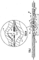
The light source 10 of the present invention in the form of an elongated fused quartz
envelope is shown in more detail in FIG. 1 as being a double ended structure having a pair of
elongated electrodes 16 (cathode) and 18 (anode) disposed at opposite ends of neck sections
36 and 38, respectively. The electrodes are separated from each other by a predetermined
critical distance D or arc gap preferably in the range of about 0.8 mm to about 1.5 mm. The
light source is in the shape of an elongated body having an overall length (L in FIG. 1) in the
range of about 28 mm to about 32 mm having the neck sections with a diameter in the range
of about 3 mm to about 5 mm, and has a generally ellipsoidal shaped central hermetically
sealcd chamber 12 having a volume 14 of about 130 mm3± 20 mm3. The wall. thickness of
chamber 12 is about I mm. The light source contains a critical fill mix which comprises an
inert noble gas, mercury and metal halides which are formulated to enhance, UV output.
More specifically, the sealed chamber is designed to provide a unique UV spectral
response for the lamp of the present invention as evidenced by the plot of spectral power in
the UV range of about 300-600 nm as shown in FIG. 4. The radiation illustrated in FIG. 4 is
obtained from the lamp described herein operated at 50W with a spectroradiometer traceable
to NIST standards.
The volume of the chamber can be approximated to that of an ellipsoid of semi-major
axis a and semi-minor axis b.
V=4/3πb2.a
The semi-major axis length (a in FIG. la) for the light source of the present invention is one
half of the overall chamber length and in a range of about 4 to 6 mm. The semi-minor axis
length (b in FIG. la) is one half of the chamber inner diameter and has a range of about 2 to 3
mm.
The preferred range of the chamber volume to yield optimal performance
specifications is about 110 to 150 mm3. The lamp power divided by the chamber volume is
known as the volume-power loading of the lamp. This number calculates out to be 0.4/mm3
given the preferred range of design factors. This metric is significant because it relates to the
amount of heat dissipated power unit size of the lamp and therefore influences the operating
temperature of the lamp.
The appropriate volume of the chamber is determined in combination with other
interrelated design factors, primarily the type and amount of fill materials and operating
power.
Deviation from the optimal volume could lead to performance degradation as a result
of either improper internal operating pressure or improper thermal operation as dictated by
the volume-power loading.
The electrodes respectively consist of a shank portion the ends of which contain
wrapped metal coils 20 and 22, respectively. Proper thermal and electrical design of
electrodes arc required to achieve the desired performance. Coils, or wraps of wire, around
the primary electrode shank can be added to properly balance the electrical and thermal
requirements. Coils can serve the function of providing an additional thermal radiative
surface to control the temperature of the electrode shank. The size and length of the coil can
be designed to achieve optimal thermal performance. An additional function of coils is to
provide the appropriate electrical field properties for efficient and reliable arc initiation, or
lamp starting. In certain applications, the coil on the cathode is optional and is not required.
The opposite end of the shank portions are respectively connected to one end of a foil
member 28 and 30 respectively sealed in the opposite end of the neck portion. Typically, the
foil mcmbers are made of molybdenum. The foil members have their other end respectively
connected to relatively thicker outer lead wires 32 and 34 which in turn are respectively
connectcd to the structural members shown more clearly in FIG. 2.
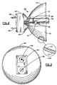
FIG. 2 illustrates the miniature lamp 40 of the present invention which includes a
reflector 42 containing the light source 10 having an insulating thermally resistant connector
44 having a pair of pins 46 and 48 suitable for connection to a suitable source of power.
Structural members 35, 37 and 39 are used to orient the light source in a substantial
horizontal axis with respect to the reflector and form the electrical connections along with
lead wire 32. The reflector internal glass surface 43 further contains a coating of dichroic
material 45 which function to transmit selected light, and reflect or direct UV radiation to a
desired target or location. Suitable dichroic materials are combinations of silicon dioxide
(S1O2), aluminum oxide (Al2O3), zirconium dioxide (ZrO2), or tantalum oxide (Ta2O5).
Multiple coatings are applied in alternating layers, The dichroic coating is a submicron layer,
typically about .005 to .010 microns thick. Multiple coatings (up to 100) of at least two
different oxides are alternately formed on the inside surface of the reflector by a conventional
vapor deposition technique.
In the present invention, a refractory, insulating material is formed into an elongated
envelope into which the following components are inserted and hermetically sealed:
The electrodes are aligned in an axial manner facing each other. The light source is operating
in a direct current (DC) mode at a low electrical power.
Refractory materials for the envelope can be fused silica or alumina oxide. The
refractory materials for the electrodes typically are tungsten (with or without thorium) or
molybdenum. The description of electrodes is defined in more detail below. The metal
halide materials and quantity of mercury is also described below.
Preferably the envelope material is fused silica and the electrodes are tungsten. Fused
silica is easier to handle and process, and tungsten allows for higher operating temperatures
and increases light output and life.
The opposing electrodes are set apart and separated at a distance to provide optimal
performances for projection display applications Maximum utilization of optical component
light collection requires the light source to be as near to "point source" as possible.
The broad range of separation is 0.8 mm to 1.5 mm.
The preferred range of separation is 1.2 mm±0.2mm.
Falling below the preferred range of separation will cause a corresponding loss in
lamp luminous efficacy. Exceeding the preferred range will minimize the effectiveness of the
lamp as a miniature source for projection optics.
In operating the light source in a DC mode, one electrode is identified as the anode,
the other as the cathode, and each is sized appropriately for optimal operation for a given
lamp power and current. The electrodes are constructed from known techniques that
incorporate an overwound refractory metal coil attached to the metal shank, The optimal
design is determined given the range of electrical power and current over which the source is
intended to operate. The table below tabulates the electrode wire diameters and power and
current ranges for the present invention.
| | Range of Wattage: 40 W-60 W Range of Current: 0.5A-1.5A | Preferred Wattage: 50W±2W Preferred Current: 0.9 A ± .2 A |
| Anode Shank | 0.020 in. ± 0.008 in. | 0.020 in. ± 0.001 in. |
| Anode Overwind Wire | 0.010 in. ± 0.005 in. | 0.010.in.± 0.001 in. |
| Cathode Shank | 0.014 in. ± 0.004 in. | 0.014 in, ± 0.001 in. |
| Cathode Overwind | 0.005 in. ± 0.005 in. | 0.007 in. ± 0.001 in. |
| Wire |
A mismatch between electrical operating characteristics and electrode design could be
disastrous from a product performance standpoint. Generally, a design that permits too high
of an operating temperature of the electrodes (high current/small electrodes) will result in
rapid electrode erosion, darkening of the envelope, short life and low light output. Too low
of an operating temperature of the electrode (low power/large electrodes) will result in an
unstable or flickering arc.
In has been discovered that a unique metal halide mixture of individual compounds
selected from the following group of scandium iodide, indium iodide, cesium iodide, and
sodium iodide in conjunction with the other fill components results in a lamp which exhibits
enhanced UV output. It is the specific dose of metal halide salts in combination with a
reflector having a dichroic coating that concentrates only the desired UV radiation that is the
key combination of components of the present invention.
The scandium iodide, or any other suitable lanthanide, provides a means of
controlling undesired secondary processes within the lamp. The indium iodide contributes
radiation emission in the blue to ultraviolet regions to enhance the total spectral output
fundamental to this invention. The sodium iodides and cesium iodides are introduced in
combination to provide the appropriate electrical, thermal, and convective characteristics of
the plasma.
A suitable mixture, shown in the table below, which accomplishes the objectives of
the present invention is a metal halide dose of 132
µg of material composed of (by mass
percent). The operative concentration range which provides a combination that optimize
stable electrical behavior is also listed in the table below:
| Compound | Mass Percent (Wt. %) | Operative Range |
| ScI3 | 10.9 | 5-25 µg |
| InI | 5.0 | 3-15 µg |
| NaI | 79.1 | 10-200 µg |
| CsI | 5.0 | 10-200 µg |
The quantity of mercury is added such that it will evaporate and enter the discharge in
a gaseous state and regulate the electrical operational parameters.
The amount of mercury can range from 5 to 15 milligrams and is a function of the
internal volume of the envelope.
The preferred amount being about 9 milligrams ± -10%.
Excess mercury will cause excess pressure within the bulb and could result in early
failure. Too low of an amount of Hg could result in improper electrical operating
characteristics, primarily thereby reducing luminous efficacy.
The fill inert gas is added to provide a gas that can be ionized to aid in the starting of
the lamp. Suitable fill gasses include Ne, Ar, Kr, and Xe with cold fill pressures in the range
of 0.5 atm to several atmospheres.
A preferred gas for use in the present invention is Ar at about 500 Torr±2%. Excess
Ar would cause the required voltage to initiate the discharge to be very high and impose large
costs on the electrical operating circuitry.
The above specification for the electrode arc gap, quantity of metal halide, mercury,
and noble gas must be used in conjunction with an hermetically sealed chamber having a
critical volume, which in the case of the present invention is about 130 mm3±20 mm3.
The source size is dictated by the electrode separation (arc gap) in the range of 0.8
mm to 1.5 mm. The overall length of the envelope and associated structure being about 2
inches long. The service life exceeding 2,000 hrs.
The light source and lamp of the present invention has been particularly shown and
described with reference to the preferred mode as illustrated in the drawing, it will be
understood by one skilled in the art that various changes in detail may be effected therein
without departing from the spirit and scope of the invention as defined by the claims.