EP1134593A1 - Communication method for measuring distance between mobile bodies - Google Patents
Communication method for measuring distance between mobile bodies Download PDFInfo
- Publication number
- EP1134593A1 EP1134593A1 EP01104807A EP01104807A EP1134593A1 EP 1134593 A1 EP1134593 A1 EP 1134593A1 EP 01104807 A EP01104807 A EP 01104807A EP 01104807 A EP01104807 A EP 01104807A EP 1134593 A1 EP1134593 A1 EP 1134593A1
- Authority
- EP
- European Patent Office
- Prior art keywords
- distance
- vehicle
- mobile bodies
- communication
- measuring
- Prior art date
- Legal status (The legal status is an assumption and is not a legal conclusion. Google has not performed a legal analysis and makes no representation as to the accuracy of the status listed.)
- Granted
Links
- 238000004891 communication Methods 0.000 title claims abstract description 66
- 238000000034 method Methods 0.000 title claims abstract description 43
- 238000001228 spectrum Methods 0.000 claims abstract description 11
- 238000005562 fading Methods 0.000 abstract description 9
- 238000005259 measurement Methods 0.000 abstract description 8
- 230000005540 biological transmission Effects 0.000 description 3
- 238000010586 diagram Methods 0.000 description 3
- 230000001360 synchronised effect Effects 0.000 description 2
- 238000000605 extraction Methods 0.000 description 1
Images


Classifications
-
- G—PHYSICS
- G01—MEASURING; TESTING
- G01S—RADIO DIRECTION-FINDING; RADIO NAVIGATION; DETERMINING DISTANCE OR VELOCITY BY USE OF RADIO WAVES; LOCATING OR PRESENCE-DETECTING BY USE OF THE REFLECTION OR RERADIATION OF RADIO WAVES; ANALOGOUS ARRANGEMENTS USING OTHER WAVES
- G01S13/00—Systems using the reflection or reradiation of radio waves, e.g. radar systems; Analogous systems using reflection or reradiation of waves whose nature or wavelength is irrelevant or unspecified
- G01S13/74—Systems using reradiation of radio waves, e.g. secondary radar systems; Analogous systems
- G01S13/82—Systems using reradiation of radio waves, e.g. secondary radar systems; Analogous systems wherein continuous-type signals are transmitted
-
- G—PHYSICS
- G01—MEASURING; TESTING
- G01S—RADIO DIRECTION-FINDING; RADIO NAVIGATION; DETERMINING DISTANCE OR VELOCITY BY USE OF RADIO WAVES; LOCATING OR PRESENCE-DETECTING BY USE OF THE REFLECTION OR RERADIATION OF RADIO WAVES; ANALOGOUS ARRANGEMENTS USING OTHER WAVES
- G01S13/00—Systems using the reflection or reradiation of radio waves, e.g. radar systems; Analogous systems using reflection or reradiation of waves whose nature or wavelength is irrelevant or unspecified
- G01S13/88—Radar or analogous systems specially adapted for specific applications
- G01S13/93—Radar or analogous systems specially adapted for specific applications for anti-collision purposes
- G01S13/931—Radar or analogous systems specially adapted for specific applications for anti-collision purposes of land vehicles
-
- G—PHYSICS
- G01—MEASURING; TESTING
- G01S—RADIO DIRECTION-FINDING; RADIO NAVIGATION; DETERMINING DISTANCE OR VELOCITY BY USE OF RADIO WAVES; LOCATING OR PRESENCE-DETECTING BY USE OF THE REFLECTION OR RERADIATION OF RADIO WAVES; ANALOGOUS ARRANGEMENTS USING OTHER WAVES
- G01S13/00—Systems using the reflection or reradiation of radio waves, e.g. radar systems; Analogous systems using reflection or reradiation of waves whose nature or wavelength is irrelevant or unspecified
- G01S13/74—Systems using reradiation of radio waves, e.g. secondary radar systems; Analogous systems
- G01S13/82—Systems using reradiation of radio waves, e.g. secondary radar systems; Analogous systems wherein continuous-type signals are transmitted
- G01S13/825—Systems using reradiation of radio waves, e.g. secondary radar systems; Analogous systems wherein continuous-type signals are transmitted with exchange of information between interrogator and responder
-
- G—PHYSICS
- G01—MEASURING; TESTING
- G01S—RADIO DIRECTION-FINDING; RADIO NAVIGATION; DETERMINING DISTANCE OR VELOCITY BY USE OF RADIO WAVES; LOCATING OR PRESENCE-DETECTING BY USE OF THE REFLECTION OR RERADIATION OF RADIO WAVES; ANALOGOUS ARRANGEMENTS USING OTHER WAVES
- G01S13/00—Systems using the reflection or reradiation of radio waves, e.g. radar systems; Analogous systems using reflection or reradiation of waves whose nature or wavelength is irrelevant or unspecified
- G01S13/74—Systems using reradiation of radio waves, e.g. secondary radar systems; Analogous systems
- G01S13/82—Systems using reradiation of radio waves, e.g. secondary radar systems; Analogous systems wherein continuous-type signals are transmitted
- G01S13/84—Systems using reradiation of radio waves, e.g. secondary radar systems; Analogous systems wherein continuous-type signals are transmitted for distance determination by phase measurement
-
- G—PHYSICS
- G01—MEASURING; TESTING
- G01S—RADIO DIRECTION-FINDING; RADIO NAVIGATION; DETERMINING DISTANCE OR VELOCITY BY USE OF RADIO WAVES; LOCATING OR PRESENCE-DETECTING BY USE OF THE REFLECTION OR RERADIATION OF RADIO WAVES; ANALOGOUS ARRANGEMENTS USING OTHER WAVES
- G01S13/00—Systems using the reflection or reradiation of radio waves, e.g. radar systems; Analogous systems using reflection or reradiation of waves whose nature or wavelength is irrelevant or unspecified
- G01S13/88—Radar or analogous systems specially adapted for specific applications
- G01S13/93—Radar or analogous systems specially adapted for specific applications for anti-collision purposes
- G01S13/931—Radar or analogous systems specially adapted for specific applications for anti-collision purposes of land vehicles
- G01S2013/9316—Radar or analogous systems specially adapted for specific applications for anti-collision purposes of land vehicles combined with communication equipment with other vehicles or with base stations
Definitions
- the present invention relates to a communication method for measuring a relative distance between mobile bodies including vehicles and pedestrians by wireless means.
- the own vehicle when own vehicle tries to measure a distance to the other vehicle, the own vehicle transmits a search signal to the other vehicle, and then receives a response signal from the other vehicle. As a result, the distance is measured from a time difference between the transmission and the receipt.
- the vehicles on roads may not be able to communicate with each other even within reaching distance of waves.
- the vehicle receives several overlapped waves coming through various paths as a result of reflection and diffraction from buildings, and the like.
- received waves between driving mobile bodies are influenced by fading caused by a surface of the road.
- An object of the present invention is to provide a method for measuring a distance between mobile bodies, which improves accuracy of the distance measurement between the mobile bodies by minimizing the influence of multipath and fading, and which can miniaturize a communication device.
- the present invention provides a communication method for measuring a distance between mobile bodies, wherein: regarding a communication method applied to communication between a plurality of mobile bodies using a wireless communication device equipped on each of the mobile bodies, the wireless communication device measures a distance between the mobile bodies by communication using spread spectrum method.
- the spread spectrum method is a communication method in which receiving side (measuring side) receives a spread signal from transmitting side and spreads it reversely to obtain correlation output.
- receiving side measuring side
- receives a spread signal from transmitting side and spreads it reversely to obtain correlation output.
- influence of multipath and fading is minimized resulting in improvement in accuracy of measuring distance between mobile bodies.
- Integrating a distance-measuring function into a spread spectrum data communication device eliminates the need for equipping a separate distance-measuring unit additionally and enables us to miniaturize the device. This also enables sharing of an antenna and a communication protocol facilitating simple device configuration.
- the invention described in claim 2 provides a communication method for measuring a distance between mobile bodies according to claim 1, wherein communication waves by means of the spread spectrum method includes identification information peculiar to the mobile body.
- the mobile bodies can identify each other. If distances to two or more mobile bodies are measured, a relative distance to each identified mobile body can be measured, and thereby it is possible to know relative positions of two or more mobile bodies exactly.
- FIG. 1 shows a basic configuration of communication by means of Spread Spectrum (hereinafter referred to as SS), what is called SS communication method, according to the embodiment.
- SS Spread Spectrum
- input information is information-modulated into a narrow-band information signal in a similar way to conventional communication methods.
- the narrow-band information signal is then spread-modulated using spread code (PN (Pseudo random Noise) code).
- PN Pulseudo random Noise
- This spread modulation spreads a signal band of the narrow-band information signal from several hundred times to several thousand times, and a RF circuit transmits the signal as a spread signal.
- receiving side receives the spread signal, which is spread-demodulated (operation for reconstructing the spread signal) using the same spread code as that on the transmitting side to obtain a narrow-band information signal.
- the narrow-band information signal is then demodulated and output. Contents of communication are judged from the output information.
- the outline of the SS communication method is described above.
- a relative distance between mobile bodies can be measured by this SS communication method.
- correlation output with a constant period is obtained.
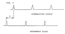
- a phase difference d between this relative output and a reference clock on the measuring side is proportional to a distance between the transmitting side and the receiving side as shown in FIG. 2, the relative distance between both mobile bodies can be determined by this phase difference d.
- phase difference d proportional to a distance between both mobile bodies
- the same spread code as that on the transmitting side is required when the spread signal is spread-demodulated on the measuring side.
- the phase difference is spread demodulated on the measuring side using the spread code synchronized by a synchronous circuit.
- the SS communication method provides measurement of a distance between both mobile bodies as well as information conveyance.
- the spread signal received on the measuring side interference and noise added during propagation are eliminated at the time of spread demodulation because the interference and the noise are not proportional to the spread code.
- each vehicle is equipped with a wireless communication device for transmitting and receiving to which the SS communication method described above is applied.
- the wireless communication device equipped on each vehicle performs broadcast every 100 ms (millisecond) using output that provides a receivable area with a radius of up to about 400 meters.
- an identification information ID of own vehicle is added to the broadcast before transmission.
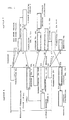
- FIG. 3 shows a communication control procedure for communication between vehicle A and B. From each wireless communication device of the vehicle A and B, own vehicle identification information IDa and IDb are transmitted as broadcast communication respectively.
- a broadcast with own vehicle identification information IDa is transmitted from the vehicle A (step S1).
- a distance measuring command C for requesting a reply required to measure a distance is added to the broadcast (step S3), and then the vehicle B transmits the broadcast with the own vehicle identification information IDb and the other vehicle identification information IDa (step S4).
- step S5 When the vehicle A receives the broadcast (step S5), the vehicle A transmits the broadcast back with both of identification information IDa and IDb (step S6).
- step S6 When the vehicle B receives this reply (step S7), a relative distance between the vehicle A and the vehicle B is calculated from the received spread signal as described above (step S8).
- step S5 when the vehicle A receives IDb, C, and IDa in step S5, the vehicle A adds a distance measuring command C to them (step S9), and then the distance measuring command C is transmitted with the own vehicle identification information IDa and the other vehicle identification information IDb (step S10).
- the vehicle B receives them (step S11), and transmits them back with both of identification information IDa and IDb (step S12).
- the vehicle A receives this reply (step S13), calculates a distance to the vehicle B from the received spread signal (step S14), and thereby a distance to the vehicle B is measured with high accuracy on the vehicle A side.
- step S21 because 100 ms (a broadcast communication period) has passed until the reply is received in step S13, the next broadcast is transmitted with own vehicle identification information IDa before receiving the reply (step S21).
- the vehicle B therefore, receives the broadcast again (step S22), and the control described above is repeated thereafter. Both of the vehicles A and B repeatedly measure a relative distance each other.
- the above example describes the case where one vehicle B exists within a 400-meter radius of the vehicle A.
- dashed lines for example, there is a case where two or more vehicles B, C, D, ... exist in proximity to the vehicle A.
- the vehicle which has measured a distance by transmitting a distance measuring command C in response to a broadcast transmitted every 100 ms, does not reply to the vehicle A after transmitting a distance measuring command C in response to the next broadcast. Instead, the vehicle replies to a distance measuring command C transmitted by another vehicle, and thereby can measure the distance to another vehicle.
- distances to the vehicle B, C, D ... is measured in succession. After distances to all vehicles are measured, a distance to the vehicle that has been measured once is measured again in succession. As a result, distances to all vehicles in proximity of the vehicle A can be measured.
- the vehicle A can know how many vehicles in the opposite lane are approaching to the intersection, and can take notice so that the vehicle A never misses a vehicle especially when turning to the right.
- a relative distance between the vehicles driving each other is measured by means of the SS communication method as described above, the influence of multipath and fading is minimized, and thereby a distance between both vehicles can be measured with high accuracy. Also, even if at least one of the two vehicles stops, a relative distance between both vehicles can be measured with high accuracy by means of the SS communication method as a matter of course.
Landscapes
- Engineering & Computer Science (AREA)
- Radar, Positioning & Navigation (AREA)
- Remote Sensing (AREA)
- Physics & Mathematics (AREA)
- Computer Networks & Wireless Communication (AREA)
- General Physics & Mathematics (AREA)
- Electromagnetism (AREA)
- Radar Systems Or Details Thereof (AREA)
- Mobile Radio Communication Systems (AREA)
Abstract
Description
- The present invention relates to a communication method for measuring a relative distance between mobile bodies including vehicles and pedestrians by wireless means.
- As communication methods for measuring a relative distance between mobile bodies, there are methods that use an extremely high frequency radar and a laser radar, and the like. However, it sometimes takes a long time in determination by a characteristic extraction algorithm, and the like, for judging whether a target is a fixed object such as a building or a mobile object such as a vehicle. High accuracy of the determination, therefore, cannot be expected.
- Under such circumstance, another method was proposed (Japanese Patent Application Laid-Open No. Hei 11-352221, and Japanese Patent Application Laid-Open No. Hei 11-352242), in which the object side also has a communication means and a relative distance is determined from a time difference between transmission and reception.
- For example, as regards measurement of a distance between two vehicles, both of which have a communication device, when own vehicle tries to measure a distance to the other vehicle, the own vehicle transmits a search signal to the other vehicle, and then receives a response signal from the other vehicle. As a result, the distance is measured from a time difference between the transmission and the receipt.
- However, in the case of the communication method described above, the vehicles on roads may not be able to communicate with each other even within reaching distance of waves. The vehicle receives several overlapped waves coming through various paths as a result of reflection and diffraction from buildings, and the like.
- This is so called multipath propagation, which exerts a significant influence upon the distance measurement.
In addition, received waves between driving mobile bodies are influenced by fading caused by a surface of the road. - Thus, it was difficult to determine a true value of measured distance with high accuracy because of multipath and fading.
The present invention is devised taking such problem into consideration. An object of the present invention is to provide a method for measuring a distance between mobile bodies, which improves accuracy of the distance measurement between the mobile bodies by minimizing the influence of multipath and fading, and which can miniaturize a communication device. - For the purpose of attaining the object described above, the present invention provides a communication method for measuring a distance between mobile bodies, wherein: regarding a communication method applied to communication between a plurality of mobile bodies using a wireless communication device equipped on each of the mobile bodies, the wireless communication device measures a distance between the mobile bodies by communication using spread spectrum method.
- The spread spectrum method is a communication method in which receiving side (measuring side) receives a spread signal from transmitting side and spreads it reversely to obtain correlation output. In this method, because a relative distance is calculated from a peak value of the correlation output obtained at the measuring side and time at a reference point, influence of multipath and fading is minimized resulting in improvement in accuracy of measuring distance between mobile bodies.
- Integrating a distance-measuring function into a spread spectrum data communication device eliminates the need for equipping a separate distance-measuring unit additionally and enables us to miniaturize the device. This also enables sharing of an antenna and a communication protocol facilitating simple device configuration.
- The invention described in
claim 2 provides a communication method for measuring a distance between mobile bodies according toclaim 1, wherein communication waves by means of the spread spectrum method includes identification information peculiar to the mobile body. - Because the communication waves by means of the spread spectrum method includes identification information peculiar to the mobile body, the mobile bodies can identify each other. If distances to two or more mobile bodies are measured, a relative distance to each identified mobile body can be measured, and thereby it is possible to know relative positions of two or more mobile bodies exactly.
- The following describes one embodiment of the present invention with reference to FIGS. 1 to 4. It is illustrated in:
- FIG. 1: A diagram illustrating a basic structure of communication by means of spread spectrum method in accordance with an embodiment of the present invention;
- FIG. 2: An explanatory diagram illustrating signals for explaining a principle of distance measurement;
- FIG. 3: A diagram illustrating communication control procedures when measuring a distance by means of SS communication method; and
- FIG. 4: A schematic plan view illustrating an example of driving conditions of vehicles.
-
- FIG. 1 shows a basic configuration of communication by means of Spread Spectrum (hereinafter referred to as SS), what is called SS communication method, according to the embodiment.
- On transmitting side, input information is information-modulated into a narrow-band information signal in a similar way to conventional communication methods. The narrow-band information signal is then spread-modulated using spread code (PN (Pseudo random Noise) code).
- This spread modulation spreads a signal band of the narrow-band information signal from several hundred times to several thousand times, and a RF circuit transmits the signal as a spread signal.
- On the other hand, receiving side (measuring side) receives the spread signal, which is spread-demodulated (operation for reconstructing the spread signal) using the same spread code as that on the transmitting side to obtain a narrow-band information signal.
The narrow-band information signal is then demodulated and output. Contents of communication are judged from the output information. - The outline of the SS communication method is described above. A relative distance between mobile bodies can be measured by this SS communication method.
In other words, as a result of the processing in which the receiving side receives and spread-demodulates a spread signal that is transmitted from the transmitting side, correlation output with a constant period is obtained. Based on the principle that a phase difference d between this relative output and a reference clock on the measuring side is proportional to a distance between the transmitting side and the receiving side as shown in FIG. 2, the relative distance between both mobile bodies can be determined by this phase difference d. - It should be noted that, in order to make a phase difference d proportional to a distance between both mobile bodies, the same spread code as that on the transmitting side is required when the spread signal is spread-demodulated on the measuring side. The phase difference is spread demodulated on the measuring side using the spread code synchronized by a synchronous circuit.
- As described above, the SS communication method provides measurement of a distance between both mobile bodies as well as information conveyance.
As regards the spread signal received on the measuring side, interference and noise added during propagation are eliminated at the time of spread demodulation because the interference and the noise are not proportional to the spread code. - Therefore, during the SS communication between the mobile bodies such as vehicles, it is possible to minimize influence of multipath and fading so that a distance between the mobile bodies can be measured with high accuracy.
- An example of communication control procedures used in actual distance measurement is described with reference to FIGS. 3 and 4, where each vehicle is equipped with a wireless communication device for transmitting and receiving to which the SS communication method described above is applied.
The wireless communication device equipped on each vehicle performs broadcast every 100 ms (millisecond) using output that provides a receivable area with a radius of up to about 400 meters. In addition, an identification information ID of own vehicle is added to the broadcast before transmission. - FIG. 3 shows a communication control procedure for communication between vehicle A and B. From each wireless communication device of the vehicle A and B, own vehicle identification information IDa and IDb are transmitted as broadcast communication respectively.
- As an actual situation, for example, as shown in FIG. 4, it is assumed that the vehicle A is driving from the left side toward an intersection, and that on the other hand from the opposite lane the vehicle B is also driving toward the intersection.
- In this situation, a broadcast with own vehicle identification information IDa is transmitted from the vehicle A (step S1). When the vehicle B receives the broadcast (step S2), a distance measuring command C for requesting a reply required to measure a distance is added to the broadcast (step S3), and then the vehicle B transmits the broadcast with the own vehicle identification information IDb and the other vehicle identification information IDa (step S4).
- When the vehicle A receives the broadcast (step S5), the vehicle A transmits the broadcast back with both of identification information IDa and IDb (step S6).
When the vehicle B receives this reply (step S7), a relative distance between the vehicle A and the vehicle B is calculated from the received spread signal as described above (step S8). - Thus, on the vehicle B side, influence of multipath and fading is minimized by the SS communication method, and thereby a distance to the vehicle A is measured with high accuracy.
- On the other hand, when the vehicle A receives IDb, C, and IDa in step S5, the vehicle A adds a distance measuring command C to them (step S9), and then the distance measuring command C is transmitted with the own vehicle identification information IDa and the other vehicle identification information IDb (step S10). The vehicle B receives them (step S11), and transmits them back with both of identification information IDa and IDb (step S12).
- The vehicle A receives this reply (step S13), calculates a distance to the vehicle B from the received spread signal (step S14), and thereby a distance to the vehicle B is measured with high accuracy on the vehicle A side.
- In the case of this example, because 100 ms (a broadcast communication period) has passed until the reply is received in step S13, the next broadcast is transmitted with own vehicle identification information IDa before receiving the reply (step S21).
- The vehicle B, therefore, receives the broadcast again (step S22), and the control described above is repeated thereafter. Both of the vehicles A and B repeatedly measure a relative distance each other.
- Judging from the distances measured in succession, it is easy to determine whether the other vehicle is coming nearer or going away.
In the situation shown in FIG. 4, the vehicles A and B can know they are approaching to each other. Therefore, the vehicle A or B never misses the other vehicle and is given a warning especially when turning to the right. - The above example describes the case where one vehicle B exists within a 400-meter radius of the vehicle A. As shown in FIG. 4 by dashed lines, for example, there is a case where two or more vehicles B, C, D, ... exist in proximity to the vehicle A. In this case, the vehicle, which has measured a distance by transmitting a distance measuring command C in response to a broadcast transmitted every 100 ms, does not reply to the vehicle A after transmitting a distance measuring command C in response to the next broadcast. Instead, the vehicle replies to a distance measuring command C transmitted by another vehicle, and thereby can measure the distance to another vehicle.
- In this manner, distances to the vehicle B, C, D ... is measured in succession. After distances to all vehicles are measured, a distance to the vehicle that has been measured once is measured again in succession. As a result, distances to all vehicles in proximity of the vehicle A can be measured.
- In the situation shown in FIG. 4, therefore, the vehicle A can know how many vehicles in the opposite lane are approaching to the intersection, and can take notice so that the vehicle A never misses a vehicle especially when turning to the right.
- Because a relative distance between the vehicles driving each other is measured by means of the SS communication method as described above, the influence of multipath and fading is minimized, and thereby a distance between both vehicles can be measured with high accuracy.
Also, even if at least one of the two vehicles stops, a relative distance between both vehicles can be measured with high accuracy by means of the SS communication method as a matter of course. - It is possible to integrate a distance-measuring function into a SS data communication device. This eliminates the need for equipping a separate distance-measuring unit additionally, and enables us to miniaturize the device. This also enables sharing of an antenna and a communication protocol facilitating simple device configuration.
- In summary it is an object to provide a method for measuring a distance between mobile bodies, which improves accuracy of the distance measurement between the mobile bodies by minimizing influence of multipath and fading, and which enables us to miniaturize a communication device.
It is provided a communication method for measuring a distance between mobile bodies, wherein regarding a communication method applied to communication between a plurality of mobile bodies using a wireless communication device equipped on each of the mobile bodies, the wireless communication device measures a distance between the mobile bodies by communication using spread spectrum method.
Claims (2)
- A communication method for measuring a distance between mobile bodies (A,B), wherein:regarding a communication method applied to communication between a plurality of mobile bodies (A,B) using a wireless communication device equipped on each of the mobile bodies (A,B),said wireless communication device measures a distance between the mobile bodies (A,B) by communication using spread spectrum method.
- A communication method for measuring a distance between mobile bodies (A,B) according to claim 1, wherein:
communication waves by means of the spread spectrum method includes identification information (IDa,IDb) peculiar to the mobile body (A,B).
Applications Claiming Priority (2)
| Application Number | Priority Date | Filing Date | Title |
|---|---|---|---|
| JP2000059814 | 2000-03-06 | ||
| JP2000059814A JP2001249175A (en) | 2000-03-06 | 2000-03-06 | Communication system for distance measurement between moving objects |
Publications (2)
| Publication Number | Publication Date |
|---|---|
| EP1134593A1 true EP1134593A1 (en) | 2001-09-19 |
| EP1134593B1 EP1134593B1 (en) | 2004-01-14 |
Family
ID=18580220
Family Applications (1)
| Application Number | Title | Priority Date | Filing Date |
|---|---|---|---|
| EP01104807A Expired - Lifetime EP1134593B1 (en) | 2000-03-06 | 2001-02-27 | Communication method for measuring distance between mobile bodies |
Country Status (3)
| Country | Link |
|---|---|
| EP (1) | EP1134593B1 (en) |
| JP (1) | JP2001249175A (en) |
| DE (1) | DE60101754T2 (en) |
Cited By (2)
| Publication number | Priority date | Publication date | Assignee | Title |
|---|---|---|---|---|
| EP1705498A4 (en) * | 2004-01-13 | 2007-04-04 | Nippon Signal Co Ltd | Reception time determining apparatus and distance measuring apparatus using the same |
| US20120143486A1 (en) * | 2009-05-07 | 2012-06-07 | Toyota Jidosha Kabushiki Kaisha | Distance detection device and collision determination device |
Citations (2)
| Publication number | Priority date | Publication date | Assignee | Title |
|---|---|---|---|---|
| EP0964389A2 (en) * | 1998-06-12 | 1999-12-15 | ATR Interpreting Telecommunications Research Laboratories | Apparatus for generating a statistical model called class bi-multigram model with bigram dependencies assumed between adjacent sequences |
| JPH11352221A (en) * | 1998-06-10 | 1999-12-24 | Honda Motor Co Ltd | Moving object detection system |
-
2000
- 2000-03-06 JP JP2000059814A patent/JP2001249175A/en active Pending
-
2001
- 2001-02-27 DE DE60101754T patent/DE60101754T2/en not_active Expired - Lifetime
- 2001-02-27 EP EP01104807A patent/EP1134593B1/en not_active Expired - Lifetime
Patent Citations (2)
| Publication number | Priority date | Publication date | Assignee | Title |
|---|---|---|---|---|
| JPH11352221A (en) * | 1998-06-10 | 1999-12-24 | Honda Motor Co Ltd | Moving object detection system |
| EP0964389A2 (en) * | 1998-06-12 | 1999-12-15 | ATR Interpreting Telecommunications Research Laboratories | Apparatus for generating a statistical model called class bi-multigram model with bigram dependencies assumed between adjacent sequences |
Non-Patent Citations (1)
| Title |
|---|
| MIZUI K ET AL: "VEHICLE-TO-VEHICLE COMMUNICATIONS AND RANGING SYSTEM USING SPREAD SPECTRUM TECHNIQUES", ELECTRONICS & COMMUNICATIONS IN JAPAN, PART I - COMMUNICATIONS,US,SCRIPTA TECHNICA. NEW YORK, vol. 79, no. 12, 1 December 1996 (1996-12-01), pages 106 - 115, XP000679210, ISSN: 8756-6621 * |
Cited By (5)
| Publication number | Priority date | Publication date | Assignee | Title |
|---|---|---|---|---|
| EP1705498A4 (en) * | 2004-01-13 | 2007-04-04 | Nippon Signal Co Ltd | Reception time determining apparatus and distance measuring apparatus using the same |
| US7443342B2 (en) | 2004-01-13 | 2008-10-28 | The Nippon Signal Co., Ltd. | Reception time determining apparatus and distance measuring apparatus using the same |
| EP2204668A1 (en) * | 2004-01-13 | 2010-07-07 | The Nippon Signal Co., Ltd. | Reception time determining apparatus and distance measuring apparatus using the same |
| US20120143486A1 (en) * | 2009-05-07 | 2012-06-07 | Toyota Jidosha Kabushiki Kaisha | Distance detection device and collision determination device |
| US8706392B2 (en) * | 2009-05-07 | 2014-04-22 | Toyota Jidosha Kabushiki Kaisha | Distance detection device and collision determination device |
Also Published As
| Publication number | Publication date |
|---|---|
| DE60101754D1 (en) | 2004-02-19 |
| DE60101754T2 (en) | 2004-07-15 |
| JP2001249175A (en) | 2001-09-14 |
| EP1134593B1 (en) | 2004-01-14 |
Similar Documents
| Publication | Publication Date | Title |
|---|---|---|
| JP4987481B2 (en) | Determining location information | |
| US7471235B2 (en) | Mode S transponder transmission signal decoder and mode S transponder transmission signal decoding method | |
| KR100335296B1 (en) | Distance detecting method and apparatus therefor | |
| US20190187242A1 (en) | System and Method for Determining Vehicle Position Based Upon Light-Based Communication Using Signal-to-Noise Ratio or Received Signal Strength Indicator | |
| JPH10148665A (en) | Relative position calculation device by vehicle-to-vehicle communication | |
| JPH10148665A5 (en) | ||
| US10218448B2 (en) | System and method for determining vehicle position based upon light-based communication and time-of-flight measurements | |
| JPH085733A (en) | Radar equipment | |
| EP1209484B1 (en) | Method and device for distance detection | |
| KR101118267B1 (en) | System and method for estimating the location of tags based on UWB | |
| EP1134593A1 (en) | Communication method for measuring distance between mobile bodies | |
| US20190154790A1 (en) | Method for determining a reception direction of a radio signal | |
| JP4460698B2 (en) | Ranging method and apparatus | |
| US6243025B1 (en) | Moving body detection system | |
| GB2378597A (en) | Object Detection Device | |
| JPH11211493A (en) | Vehicle position measuring device | |
| JP3090806B2 (en) | Vehicle identification device | |
| EP3709057B1 (en) | Radar enhanced v2x communications | |
| JP2000241537A (en) | Angle measurement device using FM-CW radar | |
| JP2981888B1 (en) | Vehicle position detection device | |
| JP4899352B2 (en) | In-vehicle radar system | |
| Masuda et al. | Experimental study on a two-frequency secondary-radar system to detect pedestrians beyond blind corners using large anechoic chamber | |
| JP3344880B2 (en) | Vehicle speed detection device | |
| JP3424007B2 (en) | Radio wave lane marker position detection method | |
| EP4733806A1 (en) | Uwb sensing system and method for static object location in vehicle parking applications |
Legal Events
| Date | Code | Title | Description |
|---|---|---|---|
| PUAI | Public reference made under article 153(3) epc to a published international application that has entered the european phase |
Free format text: ORIGINAL CODE: 0009012 |
|
| AK | Designated contracting states |
Kind code of ref document: A1 Designated state(s): AT BE CH CY DE DK ES FI FR GB GR IE IT LI LU MC NL PT SE TR Kind code of ref document: A1 Designated state(s): DE FR GB IT |
|
| AX | Request for extension of the european patent |
Free format text: AL;LT;LV;MK;RO;SI |
|
| 17P | Request for examination filed |
Effective date: 20011213 |
|
| AKX | Designation fees paid |
Free format text: DE FR GB IT |
|
| 17Q | First examination report despatched |
Effective date: 20020610 |
|
| GRAP | Despatch of communication of intention to grant a patent |
Free format text: ORIGINAL CODE: EPIDOSNIGR1 |
|
| GRAS | Grant fee paid |
Free format text: ORIGINAL CODE: EPIDOSNIGR3 |
|
| GRAA | (expected) grant |
Free format text: ORIGINAL CODE: 0009210 |
|
| AK | Designated contracting states |
Kind code of ref document: B1 Designated state(s): DE FR GB IT |
|
| REG | Reference to a national code |
Ref country code: GB Ref legal event code: FG4D |
|
| REF | Corresponds to: |
Ref document number: 60101754 Country of ref document: DE Date of ref document: 20040219 Kind code of ref document: P |
|
| ET | Fr: translation filed | ||
| PLBE | No opposition filed within time limit |
Free format text: ORIGINAL CODE: 0009261 |
|
| STAA | Information on the status of an ep patent application or granted ep patent |
Free format text: STATUS: NO OPPOSITION FILED WITHIN TIME LIMIT |
|
| 26N | No opposition filed |
Effective date: 20041015 |
|
| PGFP | Annual fee paid to national office [announced via postgrant information from national office to epo] |
Ref country code: GB Payment date: 20080227 Year of fee payment: 8 |
|
| PGFP | Annual fee paid to national office [announced via postgrant information from national office to epo] |
Ref country code: FR Payment date: 20080208 Year of fee payment: 8 |
|
| GBPC | Gb: european patent ceased through non-payment of renewal fee |
Effective date: 20090227 |
|
| REG | Reference to a national code |
Ref country code: FR Ref legal event code: ST Effective date: 20091030 |
|
| PG25 | Lapsed in a contracting state [announced via postgrant information from national office to epo] |
Ref country code: FR Free format text: LAPSE BECAUSE OF NON-PAYMENT OF DUE FEES Effective date: 20090302 Ref country code: GB Free format text: LAPSE BECAUSE OF NON-PAYMENT OF DUE FEES Effective date: 20090227 |
|
| PGFP | Annual fee paid to national office [announced via postgrant information from national office to epo] |
Ref country code: IT Payment date: 20110219 Year of fee payment: 11 Ref country code: DE Payment date: 20110223 Year of fee payment: 11 |
|
| PG25 | Lapsed in a contracting state [announced via postgrant information from national office to epo] |
Ref country code: IT Free format text: LAPSE BECAUSE OF NON-PAYMENT OF DUE FEES Effective date: 20120227 |
|
| REG | Reference to a national code |
Ref country code: DE Ref legal event code: R119 Ref document number: 60101754 Country of ref document: DE Effective date: 20120901 |
|
| PG25 | Lapsed in a contracting state [announced via postgrant information from national office to epo] |
Ref country code: DE Free format text: LAPSE BECAUSE OF NON-PAYMENT OF DUE FEES Effective date: 20120901 |