EP1134502A2 - System for fixing tubes, hoses or other conduits in a road surface - Google Patents
System for fixing tubes, hoses or other conduits in a road surface Download PDFInfo
- Publication number
- EP1134502A2 EP1134502A2 EP01200957A EP01200957A EP1134502A2 EP 1134502 A2 EP1134502 A2 EP 1134502A2 EP 01200957 A EP01200957 A EP 01200957A EP 01200957 A EP01200957 A EP 01200957A EP 1134502 A2 EP1134502 A2 EP 1134502A2
- Authority
- EP
- European Patent Office
- Prior art keywords
- openings
- elements
- excavations
- tubes
- hoses
- Prior art date
- Legal status (The legal status is an assumption and is not a legal conclusion. Google has not performed a legal analysis and makes no representation as to the accuracy of the status listed.)
- Granted
Links
Images


Classifications
-
- E—FIXED CONSTRUCTIONS
- E01—CONSTRUCTION OF ROADS, RAILWAYS, OR BRIDGES
- E01C—CONSTRUCTION OF, OR SURFACES FOR, ROADS, SPORTS GROUNDS, OR THE LIKE; MACHINES OR AUXILIARY TOOLS FOR CONSTRUCTION OR REPAIR
- E01C11/00—Details of pavings
- E01C11/24—Methods or arrangements for preventing slipperiness or protecting against influences of the weather
- E01C11/26—Permanently installed heating or blowing devices ; Mounting thereof
-
- F—MECHANICAL ENGINEERING; LIGHTING; HEATING; WEAPONS; BLASTING
- F24—HEATING; RANGES; VENTILATING
- F24D—DOMESTIC- OR SPACE-HEATING SYSTEMS, e.g. CENTRAL HEATING SYSTEMS; DOMESTIC HOT-WATER SUPPLY SYSTEMS; ELEMENTS OR COMPONENTS THEREFOR
- F24D3/00—Hot-water central heating systems
- F24D3/12—Tube and panel arrangements for ceiling, wall, or underfloor heating
- F24D3/14—Tube and panel arrangements for ceiling, wall, or underfloor heating incorporated in a ceiling, wall or floor
- F24D3/141—Tube mountings specially adapted therefor
-
- Y—GENERAL TAGGING OF NEW TECHNOLOGICAL DEVELOPMENTS; GENERAL TAGGING OF CROSS-SECTIONAL TECHNOLOGIES SPANNING OVER SEVERAL SECTIONS OF THE IPC; TECHNICAL SUBJECTS COVERED BY FORMER USPC CROSS-REFERENCE ART COLLECTIONS [XRACs] AND DIGESTS
- Y02—TECHNOLOGIES OR APPLICATIONS FOR MITIGATION OR ADAPTATION AGAINST CLIMATE CHANGE
- Y02B—CLIMATE CHANGE MITIGATION TECHNOLOGIES RELATED TO BUILDINGS, e.g. HOUSING, HOUSE APPLIANCES OR RELATED END-USER APPLICATIONS
- Y02B30/00—Energy efficient heating, ventilation or air conditioning [HVAC]
Definitions
- the invention relates to a system for fixing hoses, tubes or other conduits or elongated elements on a foundation onto which still a layer of material has to be applied, which system comprises a number of elements which in the operational situation extend over a predetermined distance upwards, which elements are made of a material which is shaped into strips and which elements comprise openings or excavations which in the operational situation will receive a part of a hose, tube, conduit or other elongated element and will fix said part approximately parallel to the foundation
- FR-2293675 describes an embodiment whereby the strips are combined into a rectangular lattice so that each of the elongated elements is at regular intervals inserted into an opening or excavation of a rib and supported by said rib.
- FR-2344687 describes an embodiment whereby rather voluminous ribs are used. Also these ribs can be combined into lattices for providing support over a larger surface.
- DE-3513971 provides a solution whereby the strips are bended such that Omega-shaped forms are obtained, each of which can be used for inserting a tube or other elongated element.
- a problem with the rather thin ribs as for instance used in FR-2293675 is that in many cases they do not provide sufficient stability.
- the road surface material has to be spread over the system.
- relatively large machines are used which spread out the asphalt over the width of one or even two lanes on the foundation such that over the whole width an equal layer of hot granular asphalt is applied.
- the said hot and non-consistent layer is pressed by means of a roller so that a consistent layer is formed.
- conduits or hoses are applied on the foundation without further protecting measures and asphalt is poured thereon and rolled, then these conduits have to be resistant against the relatively large weights of the pouring machines and the rollers. That is not always the case.
- An object of the invention is now to provide means on the basis of the above-mentioned existing technology for eliminating the above-mentioned disadvantages.
- the invention now provides a system of the type described in the first paragraph which according to the invention is characterized in that the thickness of the strips is increased around the edges of said openings or excavations.
- the object of the invention is also fulfilled by a system of the type mentioned in the first paragraph, which is characterized in that at least part of the inner wall of at least part of the openings or excavations is non-smooth.
- both above-mentioned characteristics are combined in a system of the type mentioned in the first paragraph which according to the invention is characterized in that the thickness of the strips is increased around the edges of said openings or excavations and that at least part of the inner wall of at least part of the openings or excavations is non-smooth.
- a number of combinations can be interconnected into a lattice such that this lattice covers a predetermined surface.
- large scale lattices can be created which can be combined first of all with tubes or hoses.
- the lattice is put on its back and the hoses or tubes are pressed into the excavations or openings such that the tube or hose will take a meandering-shaped pattern whereby the ends of the hoses for instance end near an edge of the lattice such that these ends are accessible afterwards.
- the lattice with the therein fixed hose or tube is turned around and positioned at its location on the foundation. Because the lattice is made of strip-shaped material which in the operating situation extends upwards from the foundation the lattice has an inherent stiffness and also the tube or hose which is fixed in said lattice has no ability to move in any direction and will therefore stay neatly flat on the foundation.
- the openings or excavations are made such that at least a part of said openings or excavations is aligned.
- the system is embodied such that the openings or excavations have in general an inverted U-shaped cross section whereby the height of the opening is at least equal to the width thereof.
- Such an embodiment is very suited for application with hoses or tubes which can be relatively easy in the desired shape.
- the tube or hose can be fixed in a series of U-shaped openings tight enough to be able to turn the lattice around without the tube or hose falling out and to install the lattice at its right location. Is the height of the opening exactly equal to the width thereof then in the operating situation the tube will rest onto the foundation.
- openings or excavations When used in combination with hoses or tubes made of a more unmanageable material it may be useful to embody the system such that the openings or excavations have an Omega-shaped cross section with at both sides at short distance thereof two saw cuts having such a length that they extend at least to the widest part of the Omega shape and preferably up to the upper side of the Omega shape. Openings or excavations with an Omega shape have an access opening which is smaller than the diameter of the hose or tube which has to be inserted into said Omega shape. Such a shape of the opening is only possible if hoses or tubes of a somewhat flexible material are applied.
- the legs of the Omega shape as a result of the saw cuts at both sides can be bent resiliently outwards, so that the hose or tube or other conduit can be inserted into Omega shape.
- the openings or excavations at least at those locations where the wall thereof is in contact with the tube, hose or conduit or similar element, have a toothed, ribbed or similar non-smooth wall.
- excavations or openings can be made both at the underside of the elements (whereby the tubes or hoses are laying directly on the foundation) or at the upper side whereby the tubes or hoses in general have some distance to the foundation.
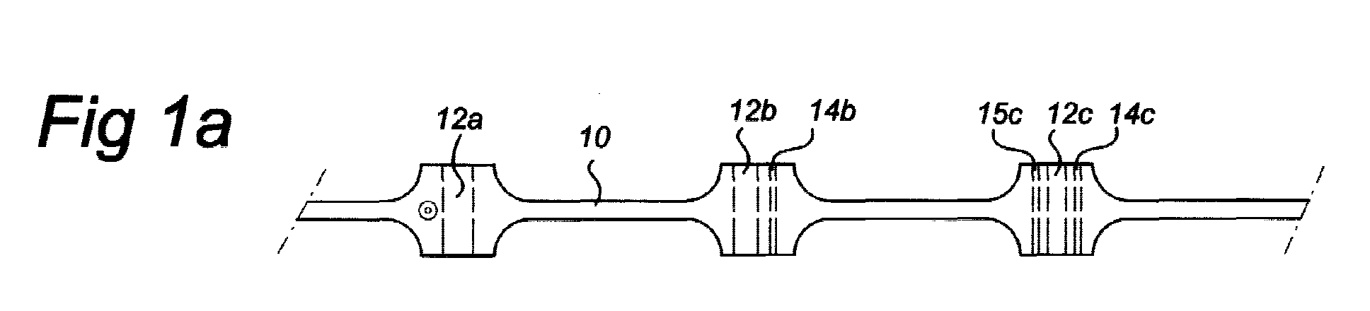
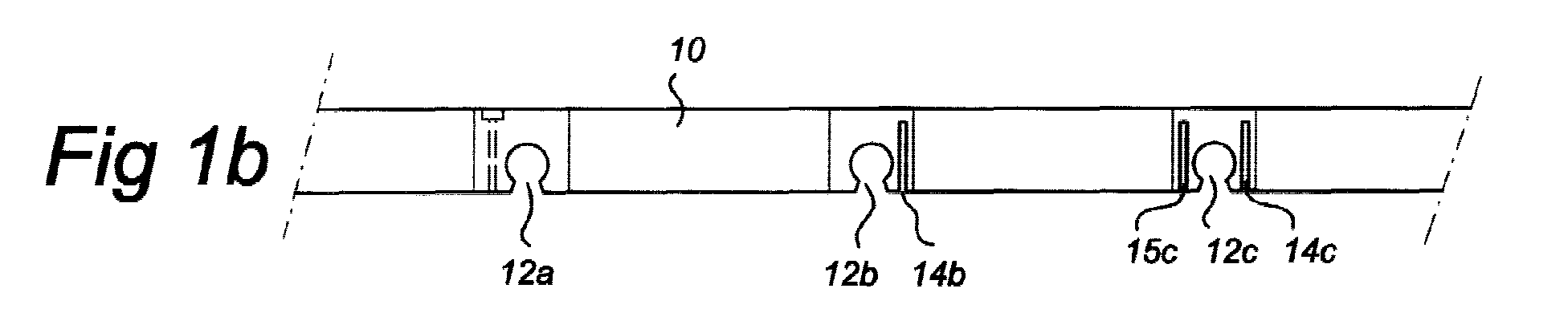
- Figure 1 illustrates in two views figure 1a and figure 1b an embodiment of a strip-shaped element by means of which the goal of the invention is fulfilled.
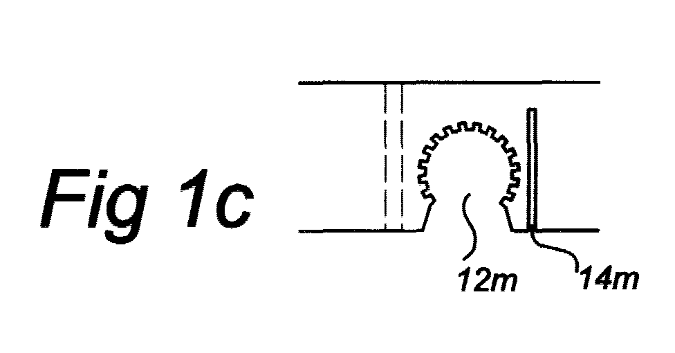
- Figures 1c and 1d indicate variants which can be applied.
- Figure 2 illustrates the application of a number of elements in figure 1 for fixating a number of tubes on a foundation.
- Figure 3 illustrates a second embodiment of a system according to the invention, in this case embodied as a lattice-shaped construction from strip-shaped elements.
- Figure 4 illustrates a perspective view of a part of the lattice construction according to figure 3 at the location where one of the tubes which is fixed by said lattice construction, makes a turn.
- Figure 5 illustrates the application of the invention with a prior art lattice construction.
- Figure 6 illustrates the application of the invention also on the basis of another prior art lattice construction.
- Figure 7a illustrates the embodiment of upwards directed openings or excavations in the elements whereby the hoses or tubes are not directly resting onto the foundation.
- Figure 7b illustrates a further developed embodiment based on figure 7a.
- Figures 8a and 8b show in cross section the shape of the transversal ribs.
- Figure 9 illustrates an example of a lattice element whereby at two adjacent sides there are sidewalls present whereas at the other two adjacent sides no sidewalls are present.
- Figure 10 illustrates an embodiment in which the openings for the tubes, hoses, etcetera, have an Omega shape and are delimited by further openings such that the hoses, tubes, etcetera are in fact clamped in between two legs.
- FIG. 1a A first embodiment of the system according to the invention is illustrated in figures 1a and 1b.
- the system is realized as a strip-shaped element 10 comprising a number of Omega-shaped excavations or openings 12a, 12b, 12c, ...
- these openings are directed to the foundation onto which the strips 10 come to rest.
- the strips 10 are meant for fixing hoses made of a relatively flexible material which can be pressed relatively easy into the Omega-shaped openings, then the "bare" embodiment of figure 12a is sufficient to fulfil the object.
- the strips are applied with tubes or hoses of a relatively stiff material, then it may be necessary to make adjacent to the Omega-shaped excavation a saw cut as is illustrated with the saw cut 14b adjacent to the opening 12b.
- This saw cut 14b takes care that the right-hand wall of the Omega-shaped opening 12b in this figure can bend somewhat so that space is provided for inserting a more stiff tube. If necessary at both sides of the Omega-shaped opening a saw cut can be made such as the saw cuts 14c and 15c, adjacent to the opening 12c. In this case both sidewalls of the Omega-shaped opening are able to bend away somewhat for inserting the tube, hose or other conduit.
- the strip 10 near the openings 12a, 12b, 12c with a larger thickness to compensate for the weakening which is in fact caused by making the openings 12a, 12b, 12c.
- the degree of thickening is dependent on the application. Not only a compensation is obtained for the decreased strength but furthermore a sidewards bulging is created which causes an increasing stability of the strip during operation. Thanks to these thicker parts the strip will have less tendency to tilt during the application of the material layer on the foundation, whereby the strip 10 forms the armouring.
- FIG 2 An application of a number of strips for fixing a number of conduits is illustrated in figure 2.
- the conduits 20a, 20b, 20c are fixed at their location by means of the strips 10a and 10b.
- the conduit 20c further parallel conduits 20d and 20e can be fixed at their location. All this will be clear without a further detailed elucidation of figure 2.
- the Omega-shaped openings may have an inner ribbed or toothed surface.
- this surface consists of a somewhat resilient material then such a ribbed or toothed surface can be used to get a better grip on a round hose or tube.
- hoses or tubes which have a lengthwise ribbed surface. If the pattern of the ribs on the wall of the Omega-shaped opening is adapted thereto, then it will be clear that when such a tube or hose with ribbed outer surface is applied a very good fixation can be realized.
- the use of such hoses in the upper layer of a road surface is as such described in US-5233971. However, nothing is said in said publication about armouring the road surface or about fixation of hoses as such.
- the excavation or opening does not have to Omega-shaped per se.
- a usual inverted U-shaped opening can be very functional as is indicated in figure 1d.
- the diameter d of the opening 12m is at least equal to the height h thereof. However, in some applications it may be preferable to select the height h somewhat larger than the height d.
- FIG. 4 a second embodiment of a system according to the invention is illustrated.
- a partial view in perspective is illustrated whereas in figure 3 a cross section through a lattice is illustrated near the tubes which are fixed by this lattice.
- the lattice 40 comprises in this embodiment strip-shaped ribs which in this case define 4 x 4 lattice openings.
- the part of the ribs which delimit a lattice opening do have also excavations in which tubes, hoses or other conduits can be fixed.
- the ribs which delimit the lattice opening 42a do have for instance the openings or excavations 44a, 44b, 44c, and 44d. These openings or excavations may have an Omega-shaped or inverted U-shaped embodiment just as in the afore-mentioned example.
- the tubes 46a, 46b, 46c are fixed.
- the tubes 46a and 46b extend rectilinear through the lattice and are fixed each time by means of each of the crossing ribs.
- the tube 46c is bent in the right-hand lower corner of the lattice and extends through a further section of the lattice back to the left. This bend is illustrated in more detail in figure 4.
- the thickness of the ribs is somewhat larger near the openings 44x. Therewith a compensation is provided for the weakening which in fact is caused by the making of the excavations or openings 44x.
- the invention can be applied in many cases if one starts with armouring constructions which are known as such and of which a number is mentioned already in the introductory part to the description.
- An example is provided in figure 5 of which the construction is already known from figure 4 of EP-0808947.
- the lattice structure is built from sections which are snapped into each other such that a lattice of the desired extent is constructed. If these parts are now modified by making openings or excavations in the way illustrated in figure 5, then therewith one or more tubes, hoses or other conduits can be fixed at a location in a similar manner as above illustrated with reference to the figures 1 until 4. In figure 5 in this way two rectangular extending tubes 52a and 52b are fixed at their locations. It will be clear that also in this embodiment by applying further openings or excavations constructions are possible whereby a tube for instance is fixed in a meandering pattern in the lattice.
- FIG. 6 Another example of a prior art lattice which in the inventive manner can be applied with additional excavations or openings for fixing tubes, hoses, etcetera, is illustrated in figure 6.
- a part is illustrated of the construction which is described in the German Auslegeschrift DE-1197109.
- a lattice construction with rectangular openings and walls made of a strip-shaped material is described whereby the walls are embodies hollow.
- the attention is drawn to the respective Auslegeschrift.
- a respective lattice now comprising a number of openings for fixing a tube at its location. It will be clear that more openings can be made such that in both lattice directions a tube can be fixed in a similar manner as illustrated in figure 3.
- the tubes, hoses or other conduits, which in the last mentioned embodiment are fixed into the openings or excavations will, dependent on the flexibility of the material, show a tendency to move downwards in the direction of the foundation between the various openings. In certain applications that is not allowable and in other applications it is.
- transversal ribs to each of the elements near the openings or excavations.
- FIG 7a A first example thereof is illustrated in figure 7a.
- element 50 is illustrated wherein an excavation 52 is made, which excavation in the operational situation is directed upwards.
- the tube 54 is inserted and underneath said tube at both sides of the element 50 a transversal rib 56 is installed.
- the thickness of the transversal rib 56 i.e., the dimension from the foundation upwards) is such that in the operational situation the tube 54 will rest on the rib 56 so that sagging of the tube 54 at least over the full length of this rib 56 is prevented.
- this rib 56 (the dimension perpendicular to the tube 54) is such that the intermediate distance between transversal ribs, which are extending in the same length direction mutually aligned, is small enough to prevent sagging across this intermediate distance at least partly.
- the length of the ribs equals half the intermediate distance between the elements 50, in other words, that the transversal ribs extend integral between the adjacent elements 50.
- FIG. 1a illustrates an embodiment in which the thickness of the element near an excavation is enlarged in the same way as schematically illustrated in figure 1a.
- the enlarged sections of element 50 are indicated by 56a and 56b.
- the tube 54 is better maintained better at its position.
- the thickened sections 56a and 56b are embodied such that they fluently transfer into the transversal ribs 56.
- transversal ribs such that the thickness of these transversal ribs is decreasing with increasing distance to said elements.
- FIG 8a illustrates a cross section according to VIII-VIII in figure 7 from which it appears that the thickness D of the transversal element 56 is equal all around.
- figure 8b an embodiment of the transversal element is shown of which the thickness d decreases with increasing distance to the element 50. Therewith a proper support of the tube is assured whereas a slight degree of sagging of the tube is allowed.
- Figure 9 illustrates an embodiment of a lattice-shaped construction part comprising the mutually perpendicular upwards extending ribs 60, 62, and 64 and the transversally extending ribs 66 and 68.
- openings are made in these ribs in which pipes, hoses or tubes, etcetera, can be positioned.
- reference number 70 As is extensively discussed with reference to figures 7 and 8 between these upstanding ribs transversal ribs are installed to prevent sagging of the pipes, tubes, etcetera between the upstanding ribs.
- one of these transversal ribs is indicated by 72.
- the transversal ribs 72 To compensate the loss of material which is caused in the ribs by applying the openings 70 at least partly the transversal ribs 72 have near the openings approximately triangular shaped broadened sections one of which is indicated by 74 in figure 1.
- hook-shaped upstanding parts 76a and 76b are installed in figure 9.
- the inwards extending hook ends of these parts together define a local narrowing of the opening 70, which narrowing, however, thanks to the elasticity of the material from which the ribs 76a, 76b are formed, can be enlarged at least temporarily during the insertion of a pipe, tube or similar element.
- the yielding action of the hook-shaped elements can be increased by making a saw cut over at least part of the height between the actual hook-shaped elements 76a, 76b and the respective rib 68.
- This can be preferable in case the tubes, hoses, etcetera are made of a non-yielding relatively stiff material, such as a metal.
- these saw cuts will not be necessary in case the tubes, hoses, etcetera are made of a somewhat resilient material, such as a rubber, a synthetic material, etcetera.
- the embodiment which is shown in figure 9 comprises at two adjacent side walls upwards extending ribs, i.e. the ribs 60 and 68.
- coupling elements of the female type are made, one of which is indicated by 78a.
- Male coupling elements are installed at the ends of the ribs 60, 62, and 64 which extend transversely to those sidewalls.
- one of the male coupling elements is indicated by the reference number 78b.
- the embodiment of the lattice according to figure 9 is very suited for combining into a larger lattice-shaped mat together with the therein positioned tubes, hoses, etcetera, which can be simply positioned on the foundation and at least temporarily fixed by means of nails, staples or rivets or other fastening elements.
- FIG 10 illustrates an embodiment whereby the Omega-shaped openings in the strips, destined for receiving tubes, hoses, etcetera, are bounded by further excavations. These further excavations have the effect that the Omega-shaped openings as it were are bounded by two legs which, thanks to the fact that the material of the strips is somewhat resilient, are able to bend outwards during the insertion of the tubes, hoses, etcetera.
- one of the Omega-shaped openings is indicated by 80.
- At both sides of this opening 80 further openings 82 and 84 are made so that in fact the legs 86 and 88 are formed. These both legs are extending upwards under a certain angle and are able to bend outwards such that a hose or tube can be pressed easily into the opening 80.
- a further alteration to the afore-described embodiments concerns the fact that the thickness of the strips near the crossings can be increased somewhat. That will lead as it were to columns at the crossing, one of which is indicated by 94 in figure 10.
Landscapes
- Engineering & Computer Science (AREA)
- Chemical & Material Sciences (AREA)
- Mechanical Engineering (AREA)
- Structural Engineering (AREA)
- Physics & Mathematics (AREA)
- Thermal Sciences (AREA)
- Architecture (AREA)
- Combustion & Propulsion (AREA)
- Civil Engineering (AREA)
- General Engineering & Computer Science (AREA)
- Supports For Pipes And Cables (AREA)
- Road Signs Or Road Markings (AREA)
- Road Paving Structures (AREA)
- Laying Of Electric Cables Or Lines Outside (AREA)
- Devices Affording Protection Of Roads Or Walls For Sound Insulation (AREA)
Abstract
Description
Claims (8)
- System for fixing hoses, tubes or other conduits or elongated elements on a foundation onto which still a layer of material has to be applied, which system comprises a number of elements which in the operational situation extend over a predetermined distance upwards, which elements are made of a material which is shaped into strips and which elements comprise openings or excavations which in the operational situation will receive a part of a hose, tube, conduit or other elongated element and will fix said part approximately parallel to the foundation, characterised in that the thickness of the strips is increased around the edges of said openings or excavations.
- System for fixing hoses, tubes or other conduits or elongated elements on a foundation onto which still a layer of material has to be applied, which system comprises a number of elements which in the operational situation extend over a predetermined distance upwards, which elements are made of a material which is shaped into strips and which elements comprise openings or excavations which in the operational situation will receive a part of a hose, tube, conduit or other elongated element and will fix said part approximately parallel to the foundation, characterised in that at least part of the inner wall of at least part of the openings or excavations is non-smooth.
- System for fixing hoses, tubes or other conduits or elongated elements on a foundation onto which still a layer of material has to be applied, which system comprises a number of elements which in the operational situation extend over a predetermined distance upwards, which elements are made of a material which is shaped into strips and which elements comprise openings or excavations which in the operational situation will receive a part of a hose, tube, conduit or other elongated element and will fix said part approximately parallel to the foundation, characterised in that the thickness of the strips is increased around the edges of said openings or excavations and that at least part of the inner wall of at least part of the openings or excavations is non-smooth.
- System according to any of the preceding claims, characterised in that the openings or excavations have at least at those places where the inner wall thereof comes into contact with the hose, tube, conduit or other elongated element a toothed, ribbed or similar non-smooth inner wall
- System according to one of the preceding claims, characterized in that at the location of the openings or excavations transversal ribs are attached to the elements the width of said elements being equal to the distance between the top of the excavation or opening extending from the one edge of the element and the other edge of the element.
- System according to claim 5, characterized in that the thickness of the transversal ribs is at least approximately equal at all places.
- System according to claim 5, characterized in that the thickness of the transversal ribs is decreasing with increasing distance to the element.
- System according to claim 5, 6, or 7, characterized in that the transversal ribs extending from aligned openings or excavations are at least partly interconnected.
Applications Claiming Priority (4)
| Application Number | Priority Date | Filing Date | Title |
|---|---|---|---|
| NL1014645 | 2000-03-14 | ||
| NL1014645 | 2000-03-14 | ||
| NL1015781 | 2000-07-21 | ||
| NL1015781A NL1015781C2 (en) | 2000-03-14 | 2000-07-21 | Device for fixing hoses, pipes or other pipes in a road surface. |
Publications (3)
| Publication Number | Publication Date |
|---|---|
| EP1134502A2 true EP1134502A2 (en) | 2001-09-19 |
| EP1134502A3 EP1134502A3 (en) | 2001-12-12 |
| EP1134502B1 EP1134502B1 (en) | 2004-11-24 |
Family
ID=26643143
Family Applications (1)
| Application Number | Title | Priority Date | Filing Date |
|---|---|---|---|
| EP01200957A Expired - Lifetime EP1134502B1 (en) | 2000-03-14 | 2001-03-14 | System for fixing tubes, hoses or other conduits in a road surface |
Country Status (7)
| Country | Link |
|---|---|
| EP (1) | EP1134502B1 (en) |
| AT (1) | ATE283456T1 (en) |
| DE (1) | DE60107309T2 (en) |
| DK (1) | DK1134502T3 (en) |
| ES (1) | ES2233559T3 (en) |
| NL (1) | NL1015781C2 (en) |
| PT (1) | PT1134502E (en) |
Cited By (4)
| Publication number | Priority date | Publication date | Assignee | Title |
|---|---|---|---|---|
| WO2007042331A1 (en) * | 2005-10-14 | 2007-04-19 | Kevin Herbst | Heat exchanger plate |
| EP1719852A3 (en) * | 2005-05-03 | 2010-01-20 | Uponor Innovation AB | Spacer for a reinforcement of a reinforced-concrete element, in particular of a reinforced-concrete floor |
| ITTO20110087A1 (en) * | 2011-02-02 | 2012-08-03 | Gimservice S R L | MODULAR ELEMENT DUE TO THE CONSTRUCTION OF A SCREED, SCREED AND ITS CONSTRUCTION METHOD |
| WO2021052608A1 (en) * | 2019-10-30 | 2021-03-25 | De Haas Holding B.V. | A retention device for immobilizing heating pipes in a building element |
Families Citing this family (1)
| Publication number | Priority date | Publication date | Assignee | Title |
|---|---|---|---|---|
| DE102011055488A1 (en) * | 2011-11-18 | 2013-05-23 | Rehau Ag + Co. | Method for manufacturing of load-bearing element installed in traffic region on e.g. road, involves arranging pipe and sub layer on load-absorbing element that is place on surface of main layer adhered to load-absorbing element |
Family Cites Families (19)
| Publication number | Priority date | Publication date | Assignee | Title |
|---|---|---|---|---|
| DE1197109B (en) | 1956-02-21 | 1965-07-22 | Benno Palatini | Insert for a surface covering, e.g. B. of runways, streets, floors, walls, etc. |
| NL7513905A (en) * | 1974-12-02 | 1976-06-04 | Hagemann Franz Josef | BUILT-IN ELEMENT FOR LIQUID FLAT HEATING. |
| FR2344687A1 (en) * | 1976-03-15 | 1977-10-14 | Feist Artus | Support strip for flexible plastic heating tubes - is of T-section with groove cut along edge of central part |
| AR216518A1 (en) | 1977-06-23 | 1979-12-28 | Salada E | FRAGABLE PASTE FLOORING WITH CRACK BARRIERS |
| DE8117704U1 (en) * | 1981-06-16 | 1982-01-07 | Fixotherm Gesellschaft für Entwicklung + Vertrieb von Energiesystemen mbH, 5090 Leverkusen | "Floor slab" |
| DE3204985A1 (en) * | 1982-02-12 | 1983-08-25 | Joachim 7809 Denzlingen Pfeifer | Floor with floor heating and method for laying floor heating |
| DE3513971A1 (en) * | 1985-04-18 | 1986-10-30 | I.G. Bauerhin GmbH elektro-technische Fabrik, 6466 Gründau | Mounting grating for the generally equidistant fixing of the heating wire or of the heating loops formed therefrom |
| CH664429A5 (en) * | 1987-07-14 | 1988-02-29 | Wolfram Winkler | HOLDING RAIL FOR HEATING PIPES IN UNDERFLOOR HEATING. |
| EP0454663B1 (en) | 1990-04-25 | 1993-06-16 | Solkav Solartechnik GmbH | Heat exchanger |
| US5123778A (en) | 1990-09-26 | 1992-06-23 | Bohnhoff William W | Method of paving |
| CA2056521A1 (en) | 1990-11-29 | 1992-05-30 | Kiyoshi Takashashi | Method for constructing asphalted road having heating pipe laid thereunder |
| WO1993004856A1 (en) | 1991-09-09 | 1993-03-18 | Bohnhoff William W | Mat for stabilizing particulate materials |
| FR2695154B1 (en) | 1992-09-01 | 1999-02-05 | Michel Bilic | MODULAR RULES FOR LOST FORMWORK AND METHOD FOR PRODUCING A FLOOR COVERING USING SUCH RULES. |
| IT232320Y1 (en) * | 1994-02-08 | 1999-12-17 | Co Pro Tec S R L | DEVICE FOR ANCHORING PIPES TO A SUPPORT STRUCTURE. |
| DE9421260U1 (en) | 1994-02-18 | 1995-07-27 | Eberhard, Alf Hans, 78465 Konstanz | Component for the production of surfaces with a hexagonal layout of the same side length |
| JP3392988B2 (en) * | 1995-06-22 | 2003-03-31 | コスモ工機株式会社 | Captive fittings |
| FR2748760B1 (en) | 1996-05-20 | 1998-11-13 | Screg | REINFORCED ROAD LAYER, ALVEOLAR STRUCTURE AND ELEMENT BASED ON PLASTIC MATERIAL FOR SUCH A ROAD LAYER |
| AT1237U3 (en) | 1996-10-16 | 1997-06-25 | Pordes Ag | FLOOR CONSTRUCTION, ESPECIALLY FOR SPORTS SYSTEMS OR PARKING LOTS |
| DE29704909U1 (en) * | 1997-03-18 | 1997-07-03 | Rehau Ag + Co, 95111 Rehau | Bracket for a conduit |
-
2000
- 2000-07-21 NL NL1015781A patent/NL1015781C2/en not_active IP Right Cessation
-
2001
- 2001-03-14 PT PT01200957T patent/PT1134502E/en unknown
- 2001-03-14 EP EP01200957A patent/EP1134502B1/en not_active Expired - Lifetime
- 2001-03-14 ES ES01200957T patent/ES2233559T3/en not_active Expired - Lifetime
- 2001-03-14 AT AT01200957T patent/ATE283456T1/en not_active IP Right Cessation
- 2001-03-14 DE DE60107309T patent/DE60107309T2/en not_active Expired - Lifetime
- 2001-03-14 DK DK01200957T patent/DK1134502T3/en active
Cited By (4)
| Publication number | Priority date | Publication date | Assignee | Title |
|---|---|---|---|---|
| EP1719852A3 (en) * | 2005-05-03 | 2010-01-20 | Uponor Innovation AB | Spacer for a reinforcement of a reinforced-concrete element, in particular of a reinforced-concrete floor |
| WO2007042331A1 (en) * | 2005-10-14 | 2007-04-19 | Kevin Herbst | Heat exchanger plate |
| ITTO20110087A1 (en) * | 2011-02-02 | 2012-08-03 | Gimservice S R L | MODULAR ELEMENT DUE TO THE CONSTRUCTION OF A SCREED, SCREED AND ITS CONSTRUCTION METHOD |
| WO2021052608A1 (en) * | 2019-10-30 | 2021-03-25 | De Haas Holding B.V. | A retention device for immobilizing heating pipes in a building element |
Also Published As
| Publication number | Publication date |
|---|---|
| DE60107309D1 (en) | 2004-12-30 |
| EP1134502A3 (en) | 2001-12-12 |
| EP1134502B1 (en) | 2004-11-24 |
| ATE283456T1 (en) | 2004-12-15 |
| PT1134502E (en) | 2005-04-29 |
| NL1015781C2 (en) | 2001-09-21 |
| DE60107309T2 (en) | 2005-12-08 |
| DK1134502T3 (en) | 2005-02-28 |
| ES2233559T3 (en) | 2005-06-16 |
Similar Documents
| Publication | Publication Date | Title |
|---|---|---|
| US4977931A (en) | Method of producing reinforced ribbed tubes | |
| US8136769B2 (en) | Cable tray support assembly | |
| EP1134502B1 (en) | System for fixing tubes, hoses or other conduits in a road surface | |
| US10132070B2 (en) | Flexible modular trench | |
| CA2366099A1 (en) | Interlocking truss system | |
| JP2018119268A (en) | Water stop structure provided between bridge girders | |
| KR20080108863A (en) | Shape retaining strip of strip-shaped fiber reinforcement for supporting retaining wall of reinforcement soil and construction method of strip-shaped fiber reinforcement using it | |
| US5467948A (en) | Apparatus for retaining cooling pipes for an ice rink | |
| KR100824180B1 (en) | Construction method of band-shaped fiber reinforcement for prefabricated reinforced soil retaining wall support | |
| EP2243355A1 (en) | Modular ventilated flooring in particular for stables and /or piggeries | |
| US6024329A (en) | Support device for a cableway | |
| JP7539782B2 (en) | Spacers and floor slabs | |
| US20120170982A1 (en) | Silt barrier | |
| KR100511413B1 (en) | Deck plate for construction | |
| EP1198045B1 (en) | Cable tray | |
| KR101458605B1 (en) | roof-pannel and constructing method using the roof-pannel | |
| JPH10121660A (en) | Bar type spacer for bar arrangement in composite slab valley | |
| KR100222282B1 (en) | A latticed mat of steel bar for the reinforcing concrete | |
| KR102701688B1 (en) | Clips, Ceiling Substrates and Ceiling Substrate Installation Methods | |
| KR200498804Y1 (en) | Assembling type corrugated pipe spacing spacer | |
| EP0493899B1 (en) | Universal wall connector | |
| EP0937819A2 (en) | Access means | |
| AU2004202483B2 (en) | Spacer for concrete reinforcing | |
| KR200305557Y1 (en) | Deck plate for construction | |
| JP4811630B2 (en) | U-shaped groove |
Legal Events
| Date | Code | Title | Description |
|---|---|---|---|
| PUAI | Public reference made under article 153(3) epc to a published international application that has entered the european phase |
Free format text: ORIGINAL CODE: 0009012 |
|
| AK | Designated contracting states |
Kind code of ref document: A2 Designated state(s): AT BE CH CY DE DK ES FI FR GB GR IE IT LI LU MC NL PT SE TR |
|
| AX | Request for extension of the european patent |
Free format text: AL;LT;LV;MK;RO;SI |
|
| PUAL | Search report despatched |
Free format text: ORIGINAL CODE: 0009013 |
|
| AK | Designated contracting states |
Kind code of ref document: A3 Designated state(s): AT BE CH CY DE DK ES FI FR GB GR IE IT LI LU MC NL PT SE TR |
|
| AX | Request for extension of the european patent |
Free format text: AL;LT;LV;MK;RO;SI |
|
| 17P | Request for examination filed |
Effective date: 20020530 |
|
| AKX | Designation fees paid |
Free format text: AT BE CH CY DE DK ES FI FR GB GR IE IT LI LU MC NL PT SE TR |
|
| 17Q | First examination report despatched |
Effective date: 20030729 |
|
| GRAP | Despatch of communication of intention to grant a patent |
Free format text: ORIGINAL CODE: EPIDOSNIGR1 |
|
| GRAS | Grant fee paid |
Free format text: ORIGINAL CODE: EPIDOSNIGR3 |
|
| GRAA | (expected) grant |
Free format text: ORIGINAL CODE: 0009210 |
|
| AK | Designated contracting states |
Kind code of ref document: B1 Designated state(s): AT BE CH CY DE DK ES FI FR GB GR IE IT LI LU MC NL PT SE TR |
|
| REG | Reference to a national code |
Ref country code: GB Ref legal event code: FG4D |
|
| REG | Reference to a national code |
Ref country code: CH Ref legal event code: EP |
|
| REG | Reference to a national code |
Ref country code: CH Ref legal event code: NV Representative=s name: ISLER & PEDRAZZINI AG |
|
| REF | Corresponds to: |
Ref document number: 60107309 Country of ref document: DE Date of ref document: 20041230 Kind code of ref document: P |
|
| REG | Reference to a national code |
Ref country code: IE Ref legal event code: FG4D |
|
| PGFP | Annual fee paid to national office [announced via postgrant information from national office to epo] |
Ref country code: MC Payment date: 20050218 Year of fee payment: 5 |
|
| REG | Reference to a national code |
Ref country code: GR Ref legal event code: EP Ref document number: 20050400028 Country of ref document: GR |
|
| PGFP | Annual fee paid to national office [announced via postgrant information from national office to epo] |
Ref country code: TR Payment date: 20050222 Year of fee payment: 5 |
|
| PGFP | Annual fee paid to national office [announced via postgrant information from national office to epo] |
Ref country code: PT Payment date: 20050224 Year of fee payment: 5 |
|
| PGFP | Annual fee paid to national office [announced via postgrant information from national office to epo] |
Ref country code: GR Payment date: 20050228 Year of fee payment: 5 |
|
| REG | Reference to a national code |
Ref country code: DK Ref legal event code: T3 |
|
| REG | Reference to a national code |
Ref country code: SE Ref legal event code: TRGR |
|
| PGFP | Annual fee paid to national office [announced via postgrant information from national office to epo] |
Ref country code: FI Payment date: 20050303 Year of fee payment: 5 |
|
| PGFP | Annual fee paid to national office [announced via postgrant information from national office to epo] |
Ref country code: CY Payment date: 20050311 Year of fee payment: 5 |
|
| PGFP | Annual fee paid to national office [announced via postgrant information from national office to epo] |
Ref country code: LU Payment date: 20050316 Year of fee payment: 5 |
|
| PGFP | Annual fee paid to national office [announced via postgrant information from national office to epo] |
Ref country code: FR Payment date: 20050322 Year of fee payment: 5 |
|
| PGFP | Annual fee paid to national office [announced via postgrant information from national office to epo] |
Ref country code: DK Payment date: 20050330 Year of fee payment: 5 Ref country code: ES Payment date: 20050330 Year of fee payment: 5 |
|
| REG | Reference to a national code |
Ref country code: PT Ref legal event code: SC4A Free format text: AVAILABILITY OF NATIONAL TRANSLATION Effective date: 20050224 |
|
| REG | Reference to a national code |
Ref country code: ES Ref legal event code: FG2A Ref document number: 2233559 Country of ref document: ES Kind code of ref document: T3 |
|
| ET | Fr: translation filed | ||
| PLBE | No opposition filed within time limit |
Free format text: ORIGINAL CODE: 0009261 |
|
| STAA | Information on the status of an ep patent application or granted ep patent |
Free format text: STATUS: NO OPPOSITION FILED WITHIN TIME LIMIT |
|
| 26N | No opposition filed |
Effective date: 20050825 |
|
| PG25 | Lapsed in a contracting state [announced via postgrant information from national office to epo] |
Ref country code: FI Free format text: LAPSE BECAUSE OF NON-PAYMENT OF DUE FEES Effective date: 20060314 Ref country code: CY Free format text: LAPSE BECAUSE OF NON-PAYMENT OF DUE FEES Effective date: 20060314 |
|
| PG25 | Lapsed in a contracting state [announced via postgrant information from national office to epo] |
Ref country code: ES Free format text: LAPSE BECAUSE OF NON-PAYMENT OF DUE FEES Effective date: 20060315 |
|
| PG25 | Lapsed in a contracting state [announced via postgrant information from national office to epo] |
Ref country code: DK Free format text: LAPSE BECAUSE OF NON-PAYMENT OF DUE FEES Effective date: 20060331 Ref country code: LU Free format text: LAPSE BECAUSE OF NON-PAYMENT OF DUE FEES Effective date: 20060331 Ref country code: MC Free format text: LAPSE BECAUSE OF NON-PAYMENT OF DUE FEES Effective date: 20060331 |
|
| PG25 | Lapsed in a contracting state [announced via postgrant information from national office to epo] |
Ref country code: PT Free format text: LAPSE BECAUSE OF NON-PAYMENT OF DUE FEES Effective date: 20060914 |
|
| REG | Reference to a national code |
Ref country code: DK Ref legal event code: EBP |
|
| REG | Reference to a national code |
Ref country code: PT Ref legal event code: MM4A Free format text: LAPSE DUE TO NON-PAYMENT OF FEES Effective date: 20060914 |
|
| REG | Reference to a national code |
Ref country code: FR Ref legal event code: ST Effective date: 20061130 |
|
| REG | Reference to a national code |
Ref country code: ES Ref legal event code: FD2A Effective date: 20060315 |
|
| REG | Reference to a national code |
Ref country code: CH Ref legal event code: PCAR Free format text: ISLER & PEDRAZZINI AG;POSTFACH 1772;8027 ZUERICH (CH) |
|
| PG25 | Lapsed in a contracting state [announced via postgrant information from national office to epo] |
Ref country code: FR Free format text: LAPSE BECAUSE OF NON-PAYMENT OF DUE FEES Effective date: 20060331 |
|
| PG25 | Lapsed in a contracting state [announced via postgrant information from national office to epo] |
Ref country code: GR Free format text: LAPSE BECAUSE OF NON-PAYMENT OF DUE FEES Effective date: 20061002 |
|
| PGFP | Annual fee paid to national office [announced via postgrant information from national office to epo] |
Ref country code: AT Payment date: 20090324 Year of fee payment: 9 |
|
| PGFP | Annual fee paid to national office [announced via postgrant information from national office to epo] |
Ref country code: IT Payment date: 20090320 Year of fee payment: 9 Ref country code: SE Payment date: 20090324 Year of fee payment: 9 |
|
| PG25 | Lapsed in a contracting state [announced via postgrant information from national office to epo] |
Ref country code: TR Free format text: LAPSE BECAUSE OF FAILURE TO SUBMIT A TRANSLATION OF THE DESCRIPTION OR TO PAY THE FEE WITHIN THE PRESCRIBED TIME-LIMIT Effective date: 20041124 |
|
| PGFP | Annual fee paid to national office [announced via postgrant information from national office to epo] |
Ref country code: CH Payment date: 20100329 Year of fee payment: 10 Ref country code: IE Payment date: 20100322 Year of fee payment: 10 |
|
| EUG | Se: european patent has lapsed | ||
| PG25 | Lapsed in a contracting state [announced via postgrant information from national office to epo] |
Ref country code: AT Free format text: LAPSE BECAUSE OF NON-PAYMENT OF DUE FEES Effective date: 20100314 |
|
| PG25 | Lapsed in a contracting state [announced via postgrant information from national office to epo] |
Ref country code: IT Free format text: LAPSE BECAUSE OF NON-PAYMENT OF DUE FEES Effective date: 20100314 |
|
| REG | Reference to a national code |
Ref country code: CH Ref legal event code: PL |
|
| REG | Reference to a national code |
Ref country code: IE Ref legal event code: MM4A |
|
| PG25 | Lapsed in a contracting state [announced via postgrant information from national office to epo] |
Ref country code: LI Free format text: LAPSE BECAUSE OF NON-PAYMENT OF DUE FEES Effective date: 20110331 Ref country code: CH Free format text: LAPSE BECAUSE OF NON-PAYMENT OF DUE FEES Effective date: 20110331 Ref country code: IE Free format text: LAPSE BECAUSE OF NON-PAYMENT OF DUE FEES Effective date: 20110314 |
|
| PGFP | Annual fee paid to national office [announced via postgrant information from national office to epo] |
Ref country code: BE Payment date: 20120430 Year of fee payment: 12 Ref country code: DE Payment date: 20120531 Year of fee payment: 12 |
|
| PGFP | Annual fee paid to national office [announced via postgrant information from national office to epo] |
Ref country code: GB Payment date: 20120402 Year of fee payment: 12 |
|
| PG25 | Lapsed in a contracting state [announced via postgrant information from national office to epo] |
Ref country code: SE Free format text: LAPSE BECAUSE OF NON-PAYMENT OF DUE FEES Effective date: 20100315 |
|
| BERE | Be: lapsed |
Owner name: *OOMS AVENHORN HOLDING B.V. Effective date: 20130331 |
|
| GBPC | Gb: european patent ceased through non-payment of renewal fee |
Effective date: 20130314 |
|
| REG | Reference to a national code |
Ref country code: DE Ref legal event code: R119 Ref document number: 60107309 Country of ref document: DE Effective date: 20131001 |
|
| PG25 | Lapsed in a contracting state [announced via postgrant information from national office to epo] |
Ref country code: DE Free format text: LAPSE BECAUSE OF NON-PAYMENT OF DUE FEES Effective date: 20131001 Ref country code: BE Free format text: LAPSE BECAUSE OF NON-PAYMENT OF DUE FEES Effective date: 20130331 Ref country code: GB Free format text: LAPSE BECAUSE OF NON-PAYMENT OF DUE FEES Effective date: 20130314 |
|
| PGFP | Annual fee paid to national office [announced via postgrant information from national office to epo] |
Ref country code: NL Payment date: 20200130 Year of fee payment: 20 |
|
| REG | Reference to a national code |
Ref country code: NL Ref legal event code: MK Effective date: 20210313 |