EP1134498A2 - Geschlossener Kamin, insbesondere zur Heizung von Gebäuden und Wasser zum sanitären Gebrauch - Google Patents
Geschlossener Kamin, insbesondere zur Heizung von Gebäuden und Wasser zum sanitären Gebrauch Download PDFInfo
- Publication number
- EP1134498A2 EP1134498A2 EP01105356A EP01105356A EP1134498A2 EP 1134498 A2 EP1134498 A2 EP 1134498A2 EP 01105356 A EP01105356 A EP 01105356A EP 01105356 A EP01105356 A EP 01105356A EP 1134498 A2 EP1134498 A2 EP 1134498A2
- Authority
- EP
- European Patent Office
- Prior art keywords
- fireplace unit
- labyrinth
- ducts
- enclosed fireplace
- enclosed
- Prior art date
- Legal status (The legal status is an assumption and is not a legal conclusion. Google has not performed a legal analysis and makes no representation as to the accuracy of the status listed.)
- Granted
Links
- XLYOFNOQVPJJNP-UHFFFAOYSA-N water Substances O XLYOFNOQVPJJNP-UHFFFAOYSA-N 0.000 title claims abstract description 40
- 238000010438 heat treatment Methods 0.000 title claims abstract description 12
- 238000009833 condensation Methods 0.000 claims description 4
- 230000005494 condensation Effects 0.000 claims description 4
- 239000011819 refractory material Substances 0.000 claims description 2
- 239000003517 fume Substances 0.000 description 14
- 238000004140 cleaning Methods 0.000 description 6
- 230000005855 radiation Effects 0.000 description 5
- 239000004071 soot Substances 0.000 description 4
- 238000002485 combustion reaction Methods 0.000 description 3
- 230000008021 deposition Effects 0.000 description 3
- 238000009434 installation Methods 0.000 description 2
- 229910001018 Cast iron Inorganic materials 0.000 description 1
- 230000015572 biosynthetic process Effects 0.000 description 1
- 239000011449 brick Substances 0.000 description 1
- 230000003749 cleanliness Effects 0.000 description 1
- 238000007796 conventional method Methods 0.000 description 1
- 238000001816 cooling Methods 0.000 description 1
- 230000003247 decreasing effect Effects 0.000 description 1
- 230000000670 limiting effect Effects 0.000 description 1
- 238000004519 manufacturing process Methods 0.000 description 1
- 239000000463 material Substances 0.000 description 1
- 238000000034 method Methods 0.000 description 1
- 238000012986 modification Methods 0.000 description 1
- 230000004048 modification Effects 0.000 description 1
- 230000000630 rising effect Effects 0.000 description 1
- 239000004575 stone Substances 0.000 description 1
- 238000003466 welding Methods 0.000 description 1
- 239000002023 wood Substances 0.000 description 1
Images



Classifications
-
- F—MECHANICAL ENGINEERING; LIGHTING; HEATING; WEAPONS; BLASTING
- F24—HEATING; RANGES; VENTILATING
- F24B—DOMESTIC STOVES OR RANGES FOR SOLID FUELS; IMPLEMENTS FOR USE IN CONNECTION WITH STOVES OR RANGES
- F24B1/00—Stoves or ranges
- F24B1/18—Stoves with open fires, e.g. fireplaces
- F24B1/183—Stoves with open fires, e.g. fireplaces with additional provisions for heating water
Definitions
- the present invention relates to an enclosed fireplace unit, particularly for heating buildings and sanitary water.
- a fireplace comprises a masonry structure which is usually arranged against the wall in one of the rooms of the building.
- This masonry structure is substantially constituted by a hearth, usually made of bricks, stone, cast iron or other suitable refractory material, which is more or less raised from the ground; a flame is fed on this hearth, for example by burning wood.
- a hood being directly connected to a flue which leads out onto the roof of the building, so as to collect and expel outside the fumes generated by combustion.
- fireplaces are generally used to cook or heat food, helping to heat the room almost exclusively through heat exchange by radiation.
- Enclosed fireplace units of a known type which internally comprise one or more paths for cold water arriving from the water mains or from the heating system of the building, are currently becoming commercially widespread.
- cold water circulates inside pipes or interspaces located proximate to the flame center or inside the hood, so that the water is heated by the heat generated by the flame center or by the hot fumes that flow through the hood.
- the hot water thus produced is then conveniently used as sanitary water and optionally also sent to the heating system for circulation within radiators, radiating panels or other radiating elements of a known type which are adapted for exchanging heat with the rooms of the building.
- Ash, soot and whatever is raised by the flow of hot air that surrounds the flame center and is not light enough to exit toward the flue are in fact deposited, during use, on the outer walls of the pipes and interspaces, which are an integral part of the path of the fumes.
- Some conventional enclosed fireplace units only partially solve this drawback by having systems for disassembling parts of the hood which are highly elaborate in their structure and require a considerable labour and time to perform, further allowing to achieve only partial cleaning.
- This humid surface in contact with the fumes, facilitates the deposition of ash and soot, considerably worsening the cleanliness of said fireplace.
- the aim of the present invention is to solve the above-described problems, by providing an enclosed fireplace unit which allows to achieve accurate and simple cleaning of every part thereof, particularly of the hood.
- an object of the invention is to provide an enclosed fireplace unit which minimizes the deposition of soot and ash on the internal surfaces and particularly reduces or eliminates the problem due to the condensation of water at the rear wall.
- Another object of the invention is to provide an enclosed fireplace unit which allows optimum heating of the water along the paths inside interspaces and pipes without thereby having excessive load losses.
- Another object is to provide an enclosed fireplace unit which is structurally simple and has low manufacturing costs.
- an enclosed fireplace unit particularly for heating buildings and sanitary water, which is constituted by a hearth on the perimeter whereof side walls protrude upwardly so as to delimit a firebox, a hood for connection to a flue being provided above said firebox, characterized in that at least one of said side walls is constituted by a first labyrinth-like element which is suitable for the passage of water that arrives from one or more intake ducts and is connected, in an upward region, to a plurality of hollow plates which can be accommodated in said hood, said hollow plates having a refractory element at the rear and being advantageously connected, in an upward region, to a second labyrinth-like element for connection to one or more discharge ducts.
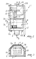
- the reference numeral 1 designates an enclosed fireplace unit which is constituted by a supporting frame 2 for a hearth 3, on the perimeter whereof side walls protrude upwardly.
- a first vertical wall 4 is arranged in a rear position and is laterally connected to a second vertical wall and a third vertical wall, designated by the reference numerals 5a and 5b respectively, which are conveniently oblique and are connected to a fourth vertical wall and to a fifth vertical wall, designated by the reference numerals 6a and 6b, which are advantageously parallel to each other and are arranged on planes which being perpendicular to said first vertical wall 4.
- a door designated by the reference numeral 7, which lies parallel to said first vertical wall 4 and can be opened so as to allow access to a firebox 8.
- the first, second and third vertical walls 4, 5a and 5b are constituted by a first labyrinth-like element, designated by the reference numeral 9, inside which there is provided a path for a stream of water that arrives from a pair of intake ducts 10a and 10b which are advantageously arranged below said hearth 3.
- the first labyrinth-like element 9 is conveniently constituted by a plurality of first ducts, generally designated by the reference numeral 11, which are arranged horizontally, are vertically packed together and are mutually connected by a plurality of bends so as to allow flow through them in succession one after the other, so as to increase heat exchange by convection between the water and the internal surface, designated by the reference numeral 12, of said first, second and third walls 4, 5a and 5b.
- Each one of the hollow plates 15 is constituted by two rectangular elements, designated by the reference numerals 16a and 16b, which are conveniently symmetrical and have curved edges and chamfered corners; on the flat surfaces 17a and 17b of the elements there are advantageously four recesses, designated by the reference numerals 18a and 18b respectively, which are advantageously circular.
- each one of the four recesses 18a of the rectangular element 16a in fact makes contact, during the assembly of the hollow plate 15, with the respective recess 18b formed in the rectangular element 16b.
- each other the respective recesses 18a and 18b rigidly couple to each other the respective recesses 18a and 18b, for example by way of conventional methods such as bolting or welding, thus assembling each one of the hollow plates 15, which advantageously can have a gasket at the regions of contact between said pair of rectangular elements 16a and 16b.
- the recesses 18a and 18b form, inside said hollow plate 15, when assembled, regions of interference for the water stream that arrives from the respective second duct 14, thus increasing the turbulence of the water and thereby effectively increasing heat exchange.
- the hollow plates 15 are advantageously accommodated inside a hood, designated by the reference numeral 19, which is arranged above said firebox 8 and is suitable to convey the fumes produced during combustion toward a flue, which is not shown in the figures.
- the hollow plates 15 are connected in an upward region, by means of respective third ducts which are designated by the reference numeral 20 and protrude horizontally in a rearward direction, to a second labyrinth-like element 21, which is advantageously L-shaped so as to protrude above the hollow plates 15.
- the second labyrinth-like element 21 is preferably constituted by a plurality of fourth ducts, generally designated by the reference numeral 22, which are also arranged horizontally, are packed together side by side and are mutually connected by a plurality of bends so as to allow flow through them in succession one after the other, thus further increasing heat exchange between the water and the second labyrinth-like element 21.
- said second labyrinth-like element 21 in fact receives from said firebox heat by radiation and by means of the flow of the fumes that exit through the hood 19.
- the water that circulates in the second labyrinth-like element 21, having heated up in passing from said pair of intake ducts 10a and 10b to the top of the enclosed fireplace unit 1, can exit from said enclosed fireplace unit by means of two discharge ducts, designated by the reference numerals 23a and 23b, which protrude vertically from said enclosed fireplace unit 1, so as to be available for heating the building and/or as sanitary water.
- An opening, designated by the reference numeral 24, can be advantageously provided between the discharge ducts 23 for the connection of the flue, and the fumes generated during combustion can be expelled through the opening 24.
- a refractory element is provided, designated by the reference numeral 25, which is adapted to prevent or at least limit the flow of heat that leaves the enclosed fireplace unit 1 toward the masonry possibly provided behind it, thus acting as a condensation-dissipating element.
- the water enters the hollow plates 15 through the respective second ducts 14.
- the water By rising along said hollow plates 15 toward the third ducts 20, the water is heated further by heat exchange with said hollow plates, since said plates receive heat by radiation from the flame center and by convection from the fumes, which exit through the hood 19 and strike their outer surfaces.
- the presence of the recesses 18a and 18b increases the exchange of heat between the water and the hollow plates 15, since it increases the turbulence of the water, avoiding or reducing laminar flow.
- the already-hot water undergoes a further temperature increase by passing through fourth ducts formed in a second labyrinth-like element 21 which protrudes above said hollow plates 15 and is also heated by radiation and convection.
- two intake ducts 10a and 10b and two discharge ducts 23a and 23b are provided not so much to allow a possible simultaneous flow of two water streams as to facilitate the installation of the enclosed fireplace unit by providing an intake duct and a discharge duct on either side of the enclosed fireplace unit.
- an enclosed fireplace unit having been provided which allows to achieve optimum heating of the water even a long time after installation, allowing to perform accurate and rapid cleaning of every part of the enclosed fireplace unit, especially of the hood.
Landscapes
- Engineering & Computer Science (AREA)
- Chemical & Material Sciences (AREA)
- Combustion & Propulsion (AREA)
- Mechanical Engineering (AREA)
- General Engineering & Computer Science (AREA)
- Heat-Exchange Devices With Radiators And Conduit Assemblies (AREA)
- Incineration Of Waste (AREA)
- Resistance Heating (AREA)
- Glass Compositions (AREA)
Applications Claiming Priority (2)
| Application Number | Priority Date | Filing Date | Title |
|---|---|---|---|
| ITMI000532 | 2000-03-15 | ||
| IT2000MI000532A IT1317623B1 (it) | 2000-03-15 | 2000-03-15 | Struttura di termocaminetto particolarmente per il riscaldamento diedifici e di acqua sanitaria. |
Publications (3)
| Publication Number | Publication Date |
|---|---|
| EP1134498A2 true EP1134498A2 (de) | 2001-09-19 |
| EP1134498A3 EP1134498A3 (de) | 2002-08-28 |
| EP1134498B1 EP1134498B1 (de) | 2004-09-15 |
Family
ID=11444467
Family Applications (1)
| Application Number | Title | Priority Date | Filing Date |
|---|---|---|---|
| EP01105356A Expired - Lifetime EP1134498B1 (de) | 2000-03-15 | 2001-03-08 | Geschlossener Kamin, insbesondere zur Heizung von Gebäuden und Wasser zum sanitären Gebrauch |
Country Status (4)
| Country | Link |
|---|---|
| EP (1) | EP1134498B1 (de) |
| AT (1) | ATE276486T1 (de) |
| DE (1) | DE60105468D1 (de) |
| IT (1) | IT1317623B1 (de) |
Family Cites Families (2)
| Publication number | Priority date | Publication date | Assignee | Title |
|---|---|---|---|---|
| US4334518A (en) * | 1980-05-28 | 1982-06-15 | Sol-Fire Inc. | Heating system |
| GB2139345A (en) * | 1983-05-05 | 1984-11-07 | Heatway Boilers Limited | Boilers for use in fireplaces |
-
2000
- 2000-03-15 IT IT2000MI000532A patent/IT1317623B1/it active
-
2001
- 2001-03-08 EP EP01105356A patent/EP1134498B1/de not_active Expired - Lifetime
- 2001-03-08 DE DE60105468T patent/DE60105468D1/de not_active Expired - Lifetime
- 2001-03-08 AT AT01105356T patent/ATE276486T1/de not_active IP Right Cessation
Also Published As
| Publication number | Publication date |
|---|---|
| IT1317623B1 (it) | 2003-07-15 |
| EP1134498B1 (de) | 2004-09-15 |
| ITMI20000532A1 (it) | 2001-09-15 |
| EP1134498A3 (de) | 2002-08-28 |
| ATE276486T1 (de) | 2004-10-15 |
| DE60105468D1 (de) | 2004-10-21 |
Similar Documents
| Publication | Publication Date | Title |
|---|---|---|
| US4149517A (en) | Grate and stove heating unit | |
| US4224921A (en) | Fireplace with air control dampers | |
| US4271815A (en) | Prefabricated fireplace for permanent installation | |
| RU2352865C1 (ru) | Печь для бани (варианты) | |
| US4334518A (en) | Heating system | |
| CN108489074B (zh) | 燃气热水装置 | |
| CA1045927A (en) | Device for transferring heat energy from a fireplace to a fluid heating system | |
| US4149519A (en) | Fireplace unit with ash disposal duct | |
| US4112914A (en) | Combined fireplace hood and heating unit | |
| US3452737A (en) | Fireplace control and heat exchange unit | |
| RU2465514C2 (ru) | Теплообменник для термокотла | |
| US4261323A (en) | Grate and stove heating unit | |
| EP1134498B1 (de) | Geschlossener Kamin, insbesondere zur Heizung von Gebäuden und Wasser zum sanitären Gebrauch | |
| US3999535A (en) | Prefabricated fireplace | |
| CA2166513C (en) | Clean face air circulating fireplace | |
| RU2038542C1 (ru) | Водогрейный котел | |
| US2494527A (en) | Sheet metal open-hearth heater | |
| EP0687351B1 (de) | Heizvorrichtung mit festen brennstoffen | |
| JPS60502065A (ja) | 加熱ボイラ−についての改良 | |
| JPH0639973B2 (ja) | 天井設置形空気調和機 | |
| US1771668A (en) | Sheet-metal fireplace | |
| RU93002653A (ru) | Бытовой котел | |
| JPH0452582Y2 (de) | ||
| US1631696A (en) | Domestic fireplace structure | |
| RU2215246C1 (ru) | Отопительный газовый котел |
Legal Events
| Date | Code | Title | Description |
|---|---|---|---|
| PUAI | Public reference made under article 153(3) epc to a published international application that has entered the european phase |
Free format text: ORIGINAL CODE: 0009012 |
|
| AK | Designated contracting states |
Kind code of ref document: A2 Designated state(s): AT BE CH CY DE DK ES FI FR GB GR IE IT LI LU MC NL PT SE TR |
|
| AX | Request for extension of the european patent |
Free format text: AL;LT;LV;MK;RO;SI |
|
| PUAL | Search report despatched |
Free format text: ORIGINAL CODE: 0009013 |
|
| AK | Designated contracting states |
Kind code of ref document: A3 Designated state(s): AT BE CH CY DE DK ES FI FR GB GR IE IT LI LU MC NL PT SE TR |
|
| AX | Request for extension of the european patent |
Free format text: AL;LT;LV;MK;RO;SI |
|
| 17P | Request for examination filed |
Effective date: 20030123 |
|
| AKX | Designation fees paid |
Designated state(s): AT BE CH CY DE DK ES FI FR GB GR IE IT LI LU MC NL PT SE TR |
|
| AXX | Extension fees paid |
Extension state: SI Payment date: 20030123 |
|
| 17Q | First examination report despatched |
Effective date: 20030924 |
|
| GRAP | Despatch of communication of intention to grant a patent |
Free format text: ORIGINAL CODE: EPIDOSNIGR1 |
|
| GRAS | Grant fee paid |
Free format text: ORIGINAL CODE: EPIDOSNIGR3 |
|
| GRAA | (expected) grant |
Free format text: ORIGINAL CODE: 0009210 |
|
| RAP1 | Party data changed (applicant data changed or rights of an application transferred) |
Owner name: GRUPPO PIAZZETTA S.P.A. |
|
| AK | Designated contracting states |
Kind code of ref document: B1 Designated state(s): AT BE CH CY DE DK ES FI FR GB GR IE IT LI LU MC NL PT SE TR |
|
| AX | Request for extension of the european patent |
Extension state: SI |
|
| PG25 | Lapsed in a contracting state [announced via postgrant information from national office to epo] |
Ref country code: AT Free format text: LAPSE BECAUSE OF FAILURE TO SUBMIT A TRANSLATION OF THE DESCRIPTION OR TO PAY THE FEE WITHIN THE PRESCRIBED TIME-LIMIT Effective date: 20040915 Ref country code: CH Free format text: LAPSE BECAUSE OF FAILURE TO SUBMIT A TRANSLATION OF THE DESCRIPTION OR TO PAY THE FEE WITHIN THE PRESCRIBED TIME-LIMIT Effective date: 20040915 Ref country code: NL Free format text: LAPSE BECAUSE OF FAILURE TO SUBMIT A TRANSLATION OF THE DESCRIPTION OR TO PAY THE FEE WITHIN THE PRESCRIBED TIME-LIMIT Effective date: 20040915 Ref country code: FR Free format text: LAPSE BECAUSE OF FAILURE TO SUBMIT A TRANSLATION OF THE DESCRIPTION OR TO PAY THE FEE WITHIN THE PRESCRIBED TIME-LIMIT Effective date: 20040915 Ref country code: LI Free format text: LAPSE BECAUSE OF FAILURE TO SUBMIT A TRANSLATION OF THE DESCRIPTION OR TO PAY THE FEE WITHIN THE PRESCRIBED TIME-LIMIT Effective date: 20040915 Ref country code: FI Free format text: LAPSE BECAUSE OF FAILURE TO SUBMIT A TRANSLATION OF THE DESCRIPTION OR TO PAY THE FEE WITHIN THE PRESCRIBED TIME-LIMIT Effective date: 20040915 Ref country code: ES Free format text: LAPSE BECAUSE OF FAILURE TO SUBMIT A TRANSLATION OF THE DESCRIPTION OR TO PAY THE FEE WITHIN THE PRESCRIBED TIME-LIMIT Effective date: 20040915 Ref country code: TR Free format text: LAPSE BECAUSE OF FAILURE TO SUBMIT A TRANSLATION OF THE DESCRIPTION OR TO PAY THE FEE WITHIN THE PRESCRIBED TIME-LIMIT Effective date: 20040915 Ref country code: BE Free format text: LAPSE BECAUSE OF FAILURE TO SUBMIT A TRANSLATION OF THE DESCRIPTION OR TO PAY THE FEE WITHIN THE PRESCRIBED TIME-LIMIT Effective date: 20040915 |
|
| REG | Reference to a national code |
Ref country code: GB Ref legal event code: FG4D Ref country code: CH Ref legal event code: EP |
|
| REG | Reference to a national code |
Ref country code: IE Ref legal event code: FG4D |
|
| REF | Corresponds to: |
Ref document number: 60105468 Country of ref document: DE Date of ref document: 20041021 Kind code of ref document: P |
|
| PG25 | Lapsed in a contracting state [announced via postgrant information from national office to epo] |
Ref country code: SE Free format text: LAPSE BECAUSE OF FAILURE TO SUBMIT A TRANSLATION OF THE DESCRIPTION OR TO PAY THE FEE WITHIN THE PRESCRIBED TIME-LIMIT Effective date: 20041215 Ref country code: GR Free format text: LAPSE BECAUSE OF FAILURE TO SUBMIT A TRANSLATION OF THE DESCRIPTION OR TO PAY THE FEE WITHIN THE PRESCRIBED TIME-LIMIT Effective date: 20041215 Ref country code: DK Free format text: LAPSE BECAUSE OF FAILURE TO SUBMIT A TRANSLATION OF THE DESCRIPTION OR TO PAY THE FEE WITHIN THE PRESCRIBED TIME-LIMIT Effective date: 20041215 |
|
| PG25 | Lapsed in a contracting state [announced via postgrant information from national office to epo] |
Ref country code: DE Free format text: LAPSE BECAUSE OF FAILURE TO SUBMIT A TRANSLATION OF THE DESCRIPTION OR TO PAY THE FEE WITHIN THE PRESCRIBED TIME-LIMIT Effective date: 20041216 |
|
| PG25 | Lapsed in a contracting state [announced via postgrant information from national office to epo] |
Ref country code: CY Free format text: LAPSE BECAUSE OF FAILURE TO SUBMIT A TRANSLATION OF THE DESCRIPTION OR TO PAY THE FEE WITHIN THE PRESCRIBED TIME-LIMIT Effective date: 20050308 Ref country code: GB Free format text: LAPSE BECAUSE OF NON-PAYMENT OF DUE FEES Effective date: 20050308 Ref country code: IE Free format text: LAPSE BECAUSE OF NON-PAYMENT OF DUE FEES Effective date: 20050308 Ref country code: LU Free format text: LAPSE BECAUSE OF NON-PAYMENT OF DUE FEES Effective date: 20050308 |
|
| PG25 | Lapsed in a contracting state [announced via postgrant information from national office to epo] |
Ref country code: MC Free format text: LAPSE BECAUSE OF NON-PAYMENT OF DUE FEES Effective date: 20050331 |
|
| REG | Reference to a national code |
Ref country code: CH Ref legal event code: PL |
|
| NLV1 | Nl: lapsed or annulled due to failure to fulfill the requirements of art. 29p and 29m of the patents act | ||
| PLBE | No opposition filed within time limit |
Free format text: ORIGINAL CODE: 0009261 |
|
| STAA | Information on the status of an ep patent application or granted ep patent |
Free format text: STATUS: NO OPPOSITION FILED WITHIN TIME LIMIT |
|
| 26N | No opposition filed |
Effective date: 20050616 |
|
| EN | Fr: translation not filed | ||
| GBPC | Gb: european patent ceased through non-payment of renewal fee |
Effective date: 20050308 |
|
| REG | Reference to a national code |
Ref country code: IE Ref legal event code: MM4A |
|
| PG25 | Lapsed in a contracting state [announced via postgrant information from national office to epo] |
Ref country code: PT Free format text: LAPSE BECAUSE OF NON-PAYMENT OF DUE FEES Effective date: 20050215 |
|
| PGFP | Annual fee paid to national office [announced via postgrant information from national office to epo] |
Ref country code: IT Payment date: 20141030 Year of fee payment: 15 |
|
| PG25 | Lapsed in a contracting state [announced via postgrant information from national office to epo] |
Ref country code: IT Free format text: LAPSE BECAUSE OF NON-PAYMENT OF DUE FEES Effective date: 20160308 |