EP1134441B1 - Roll that can be bent with a composite shell - Google Patents
Roll that can be bent with a composite shell Download PDFInfo
- Publication number
- EP1134441B1 EP1134441B1 EP01660038A EP01660038A EP1134441B1 EP 1134441 B1 EP1134441 B1 EP 1134441B1 EP 01660038 A EP01660038 A EP 01660038A EP 01660038 A EP01660038 A EP 01660038A EP 1134441 B1 EP1134441 B1 EP 1134441B1
- Authority
- EP
- European Patent Office
- Prior art keywords
- roll
- bearing
- supporting element
- face
- supported
- Prior art date
- Legal status (The legal status is an assumption and is not a legal conclusion. Google has not performed a legal analysis and makes no representation as to the accuracy of the status listed.)
- Expired - Lifetime
Links
- 239000002131 composite material Substances 0.000 title claims abstract description 13
- 238000005452 bending Methods 0.000 claims abstract description 20
- 230000002093 peripheral effect Effects 0.000 claims description 3
- 229910000831 Steel Inorganic materials 0.000 description 3
- 238000012423 maintenance Methods 0.000 description 3
- 239000010959 steel Substances 0.000 description 3
- 239000000463 material Substances 0.000 description 2
- 230000004048 modification Effects 0.000 description 2
- 238000012986 modification Methods 0.000 description 2
- 230000001276 controlling effect Effects 0.000 description 1
- 238000004519 manufacturing process Methods 0.000 description 1
- 230000001105 regulatory effect Effects 0.000 description 1
Images

Classifications
-
- F—MECHANICAL ENGINEERING; LIGHTING; HEATING; WEAPONS; BLASTING
- F16—ENGINEERING ELEMENTS AND UNITS; GENERAL MEASURES FOR PRODUCING AND MAINTAINING EFFECTIVE FUNCTIONING OF MACHINES OR INSTALLATIONS; THERMAL INSULATION IN GENERAL
- F16C—SHAFTS; FLEXIBLE SHAFTS; ELEMENTS OR CRANKSHAFT MECHANISMS; ROTARY BODIES OTHER THAN GEARING ELEMENTS; BEARINGS
- F16C23/00—Bearings for exclusively rotary movement adjustable for aligning or positioning
- F16C23/06—Ball or roller bearings
-
- B—PERFORMING OPERATIONS; TRANSPORTING
- B65—CONVEYING; PACKING; STORING; HANDLING THIN OR FILAMENTARY MATERIAL
- B65G—TRANSPORT OR STORAGE DEVICES, e.g. CONVEYORS FOR LOADING OR TIPPING, SHOP CONVEYOR SYSTEMS OR PNEUMATIC TUBE CONVEYORS
- B65G39/00—Rollers, e.g. drive rollers, or arrangements thereof incorporated in roller-ways or other types of mechanical conveyors
- B65G39/02—Adaptations of individual rollers and supports therefor
- B65G39/09—Arrangements of bearing or sealing means
-
- D—TEXTILES; PAPER
- D21—PAPER-MAKING; PRODUCTION OF CELLULOSE
- D21G—CALENDERS; ACCESSORIES FOR PAPER-MAKING MACHINES
- D21G1/00—Calenders; Smoothing apparatus
- D21G1/02—Rolls; Their bearings
- D21G1/0206—Controlled deflection rolls
-
- D—TEXTILES; PAPER
- D21—PAPER-MAKING; PRODUCTION OF CELLULOSE
- D21G—CALENDERS; ACCESSORIES FOR PAPER-MAKING MACHINES
- D21G1/00—Calenders; Smoothing apparatus
- D21G1/02—Rolls; Their bearings
- D21G1/0226—Bearings
-
- F—MECHANICAL ENGINEERING; LIGHTING; HEATING; WEAPONS; BLASTING
- F16—ENGINEERING ELEMENTS AND UNITS; GENERAL MEASURES FOR PRODUCING AND MAINTAINING EFFECTIVE FUNCTIONING OF MACHINES OR INSTALLATIONS; THERMAL INSULATION IN GENERAL
- F16C—SHAFTS; FLEXIBLE SHAFTS; ELEMENTS OR CRANKSHAFT MECHANISMS; ROTARY BODIES OTHER THAN GEARING ELEMENTS; BEARINGS
- F16C13/00—Rolls, drums, discs, or the like; Bearings or mountings therefor
- F16C13/02—Bearings
-
- B—PERFORMING OPERATIONS; TRANSPORTING
- B65—CONVEYING; PACKING; STORING; HANDLING THIN OR FILAMENTARY MATERIAL
- B65H—HANDLING THIN OR FILAMENTARY MATERIAL, e.g. SHEETS, WEBS, CABLES
- B65H2404/00—Parts for transporting or guiding the handled material
- B65H2404/10—Rollers
- B65H2404/13—Details of longitudinal profile
- B65H2404/137—Means for varying longitudinal profiles
- B65H2404/1371—Means for bending, e.g. for controlled deflection
Definitions
- the invention concerns a roll that can be bent with a composite shell as defined in the introductory part of claim 1, see WO-A-99/09329.
- the invention concerns a roll provided with a continuous tubular shell of a composite material. Due to the advantageous characteristics of the material of a composite roll, such as elastic modulus and density, the composite roll can be dimensioned so that it may be bent into the desired curvature by a moderate moment and so that it will function either at a subcritical speed, that is, below the lowest resonance frequency, or in between resonance frequencies. If it is desired to bend a steel roll into the required curvature without bringing about excessive tensions, the roll diameter must be very small. Hereby one or more critical roll speeds must unavoidably be exceeded.
- the applicant's WO Publication 99/09329 presents a roll that can be bent for a web-like material.
- the roll includes a continuous tubular roll shell of a composite material as well as axle journals connected to either end of the roll shell.
- the axle journals are attached with at least one support point to a mounting flange structure mounted to the machine frame.
- the roll includes a bending mechanism, which is used for bending the axle journals and that way the roll shell into the shape of an arc, and a control device, which is used for controlling the angular position of the roll arc.
- the roll structure according to the invention is quite simple and it needs little maintenance. Owing to its simple structure, the roll is easy to manufacture and its costs are advantageous. In addition, the simple structure facilitates maintenance of the roll.
- the roll according to the invention may be used e.g. as a spreader roll in a paper or board machine.
- Figure 1 is a basic view showing a roll provided with a shell 11 of a composite material and provided with axle journals 12.
- the roll shell 11 can be bent into the desired curvature.
- Moment M 1 may be different from moment M 2 , whereby the progress of the web proceeding on the roll shell 11 may be directed in the roll axis direction.
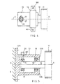
- FIG. 2 shows an embodiment of the roll according to the invention.
- the figure is a schematic longitudinal section of one end face area of the roll.
- the roll consists of a continuous tubular roll shell 11 of a composite material, at each end face of which axle journals 12 are fitted, which rotate together with the shell 11 and protrude from the end face of the shell 11.
- Each axle journal 12 is pivoted rotatingly by bearings 14, 15 located at a distance from each other in the direction X-X of the roll axis.
- An essentially tubular supporting element 13 is fitted around the axle journal 12.
- the bearing 14 located innermost in relation to the end face of the roll shell 11 is supported at its inner periphery on the axle journal 12 and at its outer periphery on the inner surface of the supporting element 13.
- the bearing 15 located outermost in relation to the roll shell 11 is supported at its inner periphery on the narrowed outer end of the axle journal 12 and at its outer periphery on a bending mechanism 20, 21 fitted into the supporting element 13 through a supporting ring 17.
- the supporting element 13 is supported at its outer periphery at the inner bearing 14 on a mounting flange 16, which for its part is mounted to the machine frame structures R. Outside the axle journal 12 on the machine maintenance side, the outer end face of the supporting element 13 is closed by an outer end face wall 13a.
- a roll driving shaft can be placed through the outer end face wall 13a.
- an inner end face wall 13b which has an opening equal in size to the cross-section of the axle journal 12 and which can be sealed to the axle journal 12.
- an inner end face wall 13b which has an opening equal in size to the cross-section of the axle journal 12 and which can be sealed to the axle journal 12.
- the shape of the supporting element 13 is essentially cylindrical.
- the end face walls 13a, 13b can be used for closing the inner space of the supporting element 13.
- the bending mechanism 20, 21 here consists of a pin 21, which is mounted to a supporting ring 17 surrounding the outer periphery of the outer bearing 15 and which is provided with an external thread and extends through the supporting element 13 and a nut 20 fitted to the pin 21 outside the supporting element 13.
- a force in the radial direction can be applied to the outer bearing 15, by which force the outer bearing 15 is deflected in relation to the central axis X-X of the unbent roll, whereby the inner bearing 14 functions as the pivoting point.
- a bearing 14 must be used here, which allows both rotating of the axle journal 12 and the pivoting motion required for bending.
- FIG 3 is a schematic cross-sectional view of the roll end face shown in Figure 2.
- the figure shows the axle journal 12, the outer bearing 15, the supporting ring 17, the supporting element 13, the nut 20, the pin 21 and the mounting flange 16.
- the mounting flange 16 consists of two halves 16a, 16b, which can be attached to each other.
- the lower half 16b of the mounting flange 16 is mounted to the machine frame structures R.
- Figure 4 is a schematic view from above of the roll end face shown in Figure 2.
- the nut 20 is supported on the outer surface of the supporting element 13 and the pin 21 is supported in the axial direction in a slot 22 formed in the supporting element 13, so that the pin 21 can be moved in the said slot 22 in the peripheral direction of the supporting element 13.
- the figure also shows mounting screws 100, 101 between the two halves 16a, 16b of the mounting flange 16.
- the angular position of the longitudinal axis of the pin 21 determines the angular position of the curvature of the shell 11.
- the shell 11 bends directly downwards, when the axle journal 12 is pulled by the pin 21 and by the nut 20 upwards, whereby the angular position of the curvature of the shell 11 is also 0°.
- the angular position of the curvature of the shell 11 may be regulated in such a way that the mounting screws 100, 101 between the two halves 16a, 16b of the mounting flange 16 are loosened, whereby the supporting element 13 can be turned in the peripheral direction, so that the longitudinal axis of the pin 21 is placed in the desired angular position.
- This regulation may be used for performing a rough control of the angular position of the curvature of the shell 11. Fine control of the angular position of the curvature of the shell 11 is performed by loosening the nut 20 and moving the pin 21 in the slot 22 in such a way that the longitudinal axis of the pin 21 is placed exactly in the desired angular position.
- the nut 20 may also be locked to the supporting element 13 in the radial direction.
- the outer bearing 15 may be deflected in opposite directions in the direction of the longitudinal axis of the pin 21.
- FIG. 5 shows a modification of the embodiment shown in Figure 2.
- the outer end face of the supporting element 13 is closed by an outer end face wall 13a outside the axle journal 12, as in the embodiment shown in Figure 2.
- the outer end face wall 13a extends outside the outer periphery of the tubular part of the supporting element 13, whereby the supporting element 13 can be mounted at its outer end face wall 13a to the machine frame structures R.
- At the inner end face of the supporting element 13 there is an inner end face wall 13b, which has an opening in size equal to the cross-section of axle journal 12 and which can be sealed to the axle journal 12.
- An inner bearing 14 and a pivot bearing 18 surrounding the former are also fitted to this inner end face wall 13b.
- the inner space of the supporting element 13 is also closed here.
- Pivot bearing 18 here functions as the pivot point, when the outer bearing 15 is deflected in relation to the central axis X-X of the unbent roll.
- one bearing instead of two concentric superimposed bearings 14, 18 one bearing may be used, which functions both as rotatory bearing and as pivot bearing.
- the outer bearing 15 is deflected in relation to the end face of roll shell 11, whereby the inner bearing 14 functions as the pivot point.
- the deflecting mechanism 20, 21 is located at the location of the inner bearing 14 and the outer bearing 15 will function as the pivot point.
- the mounting flange 16 is hereby located in connection with the outer bearing 15.
- a wedge element may be used as the deflecting part.
- the wedge element is positioned into the space between bearing 14, 15, which will be deflected, and the supporting element 13.
- a force in the radial direction can be applied to the bearing 14, 15 which will be deflected, whereby the pivot point is formed in connection with the other bearing 14, 15.
- a hydraulic cylinder-piston actuator may be used as the deflecting element.
- the cylinder is mounted in the radial direction to the supporting element 13 and the piston rod is mounted to the bearing 14, 15, which will be deflected.
- the pivot point that is, bearing 14
- the supporting element 13 again is supported on the machine frame structures R by a flange 16 supporting the supporting element 13 at the bearing 14.
- the pivot point and the supporting point are thus in the same radial plane in the axial direction X-X.
- the forces applying to the deflection point are transferred through the supporting element 13 to the supporting point, and from the supporting point the forces are transferred through the flange 16 to the machine frame structures R.
- a bending moment is applied to the mounting point between the flange 16 and the machine frame structure R.
- a supporting point is formed here through the flange 16 between the supporting element 13 and the machine frame structure R.
- the pivot point that is, pivot bearing 18, is supported on a supporting element 13, which for its part is supported on the machine frame structures R outside the axle journal 12.
- the pivot point is here in the radial plane located at the inner bearing 14, and the supporting point is in the radial plane located outside the axle journal 12.
- the forces applying to the pivot point are transferred through the supporting element 13 to the supporting point as are the forces applying to the deflection point.
- a bending moment is applied also here to the mounting point between the supporting element 14 and the machine frame structure R.
- the supporting point between the supporting element 13 and the machine frame structure R is formed here through the outer end face wall 13a of supporting element 13.
Landscapes
- Engineering & Computer Science (AREA)
- General Engineering & Computer Science (AREA)
- Mechanical Engineering (AREA)
- Rolls And Other Rotary Bodies (AREA)
- Paper (AREA)
- Reduction Rolling/Reduction Stand/Operation Of Reduction Machine (AREA)
- Laminated Bodies (AREA)
Abstract
Description
Claims (12)
- Roll that can be bent with a composite shell, said roll comprising a continuous tubular roll shell (11) of a composite material and axle journals (12) connected at each end of the roll shell (11) to rotate together with the roll shell (11), said axle journals (12) being supported on a supporting element (13) by at least two bearing elements (14, 15) located at a distance from each other in the direction of the roll axis (X-X), said supporting element (13) surrounding the axle journal (12) and the bearing elements (14, 15), characterised in that the supporting element (13) is supported on the machine frame structures (R) through one supporting point wherein the first bearing element (14, 15) is supported on the supporting element (13) through a bending mechanism (20, 21), by which a force affecting in the radial direction is applied to the first bearing element (14, 15) in order to deflect the first bearing element (14, 15) in relation to the central axis (X-X) of the unbent roll, whereby the axle journal (12) bends in relation to a pivot point which is formed at the second bearing element (14, 15) and a bending moment is applied to the roll shell (11).
- A roll as defined in claim 1, characterised in that the bending mechanism (20, 21) is formed by a pin (21) mounted to a supporting ring (17) surrounding the first bearing element (14, 15), which pin extends through an opening (22) in the supporting element (13), and by a nut (20), which is fitted on to the threaded pin (21) and which is supported against the outer surface of the supporting element (13).
- A roll as defined in claim 2, characterised in that the opening (22) is shaped as a slot, whereby the pin (21) can be moved in the peripheral direction of the supporting element (13) in order to change the angular position of the pin (21) and this way to change the angular position of the curvature of the shell (11).
- A roll as defined in any one of claims 1 to 3, characterised in that the first bearing element (15) is located outermost in relation to the roll end face and the second bearing element (14) is located innermost in relation to the roll end face, whereby the outer bearing element (15) is deflected by a bending mechanism (20, 21) fitted to the supporting element (13) at the outer bearing element (15), whereby the inner bearing element (14) functions as pivot point.
- A roll as defined in claim 4, characterised in that the supporting element (13) is supported on the machine frame structures (R) through a mounting flange (16) at the bearing element (14) located innermost and forming the pivot point.
- A roll as defined in any one of claims 1 to 3, characterised in that the first bearing element (14) is located innermost in relation to the roll end face and the second bearing element (15) is located outermost in relation to the roll end face, whereby the inner bearing element (14) is deflected by a bending mechanism (20, 21) fitted to the supporting element (13) at the inner bearing element (14), whereby the outer bearing element (15) functions as pivot point.
- A roll as defined in claim 6, characterised in that the supporting element (13) at the bearing element (14) forming the outmost pivot point is supported through a mounting flange (16) on the machine frame structures (R).
- A roll as defined in any one of claims 1 to 7, characterised in that the outer end face of the supporting element (13) is closed by an outer end face wall (13a) located in the axial direction (X-X) at a distance from the outer end face of the axle journal (12).
- A roll as defined in any one of claims 1 to 8, characterised in that the inner end face of the supporting element (13) is closed by an inner end face wall (13b) sealingly fitted on the axle journal (12).
- A roll as defined in any one of claims 1 to 9, characterised in that the outer end face wall (13a) extends outside the outer end face of the supporting element (13), and that the supporting element (13) at its outer end face wall (13a) is mounted to the machine frame structures (R) and not to the mounting flange (16).
- A roll as defined in claim 10, characterised in that the inner bearing (14) is surrounded by a pivot bearing (18), which is supported on the inner end face wall (13b) of the supporting element (13), and that the outer bearing (15) is deflected by a bending mechanism (20, 21) fitted into the supporting element (13) at the outer bearing (15).
- A roll as defined in claim 10, characterised in that the outer bearing (15) is surrounded by a pivot bearing (18), which is supported on the supporting element (13), and that the inner bearing (14) is deflected by a bending mechanism (20, 21) fitted into the supporting element (13) at the inner bearing (14).
Applications Claiming Priority (2)
| Application Number | Priority Date | Filing Date | Title |
|---|---|---|---|
| FI20000619 | 2000-03-16 | ||
| FI20000619A FI106741B (en) | 2000-03-16 | 2000-03-16 | Bendable roller with composite mantle |
Publications (3)
| Publication Number | Publication Date |
|---|---|
| EP1134441A2 EP1134441A2 (en) | 2001-09-19 |
| EP1134441A3 EP1134441A3 (en) | 2002-09-25 |
| EP1134441B1 true EP1134441B1 (en) | 2005-12-21 |
Family
ID=8557955
Family Applications (1)
| Application Number | Title | Priority Date | Filing Date |
|---|---|---|---|
| EP01660038A Expired - Lifetime EP1134441B1 (en) | 2000-03-16 | 2001-02-27 | Roll that can be bent with a composite shell |
Country Status (7)
| Country | Link |
|---|---|
| US (1) | US6592503B2 (en) |
| EP (1) | EP1134441B1 (en) |
| JP (1) | JP2002031128A (en) |
| AT (1) | ATE313728T1 (en) |
| CA (1) | CA2340870C (en) |
| DE (1) | DE60115977T2 (en) |
| FI (1) | FI106741B (en) |
Cited By (1)
| Publication number | Priority date | Publication date | Assignee | Title |
|---|---|---|---|---|
| EP2246471A2 (en) | 2009-04-29 | 2010-11-03 | Metso Paper Inc. | Method for controlling the runnability of a fiber web machine |
Families Citing this family (9)
| Publication number | Priority date | Publication date | Assignee | Title |
|---|---|---|---|---|
| DE20309301U1 (en) * | 2003-06-13 | 2003-08-28 | Stowe Woodward AG, 33758 Schloß Holte-Stukenbrock | Spreader roll |
| DE10341119A1 (en) * | 2003-09-05 | 2005-03-31 | Voith Paper Patent Gmbh | Spreader roll |
| FI116745B (en) * | 2004-07-13 | 2006-02-15 | Pr Rolls Oy | Bending roll |
| FI121825B (en) | 2005-09-01 | 2011-04-29 | Metso Paper Inc | Distribution Selection |
| DE102007012547A1 (en) * | 2007-03-13 | 2008-09-18 | Ab Skf | Bearing arrangement for horizontal mounting of cylinder-type rotating component element, particularly printing cylinder of priting machine, has bearing element with bearing receiving element |
| FI123493B (en) * | 2009-08-04 | 2013-05-31 | Finbow Oy | Fasteners for a curved roller and arrangement and method for controlling swinging of the curved roller |
| DE102012004124A1 (en) | 2012-03-01 | 2013-09-05 | EcoEnterprises GmbH | Coating device for coating curved substrate surface of rotor blade of wind-power plant, has coating roller adapted to sensor, bending apparatuses, fixture and dosing device, and regulation- and/or control unit for controlling 6-axle robot |
| NL2026544B1 (en) * | 2020-09-25 | 2022-05-30 | Dmn Machf Noordwykerhout B V | A rotary valve |
| JP7861588B2 (en) * | 2022-09-07 | 2026-05-19 | 東レ株式会社 | A method and mechanism for supporting rollers, and a web conveying device using the same. |
Family Cites Families (16)
| Publication number | Priority date | Publication date | Assignee | Title |
|---|---|---|---|---|
| US2960749A (en) * | 1958-08-20 | 1960-11-22 | Mount Hope Machinery Ltd | Expanding and contracting rolls |
| US3168435A (en) * | 1960-11-25 | 1965-02-02 | Beloit Corp | Method and means for mounting, driving and supporting rolls for endless moving bands |
| US3094771A (en) * | 1961-06-13 | 1963-06-25 | Mount Hope Machinery Ltd | Table roll with means for removing longitudinal curvature |
| US3438100A (en) | 1966-05-06 | 1969-04-15 | Beloit Eastern Corp | Adjustable shot roll |
| US3604087A (en) * | 1970-03-13 | 1971-09-14 | Beloit Corp | Antideflection roll |
| US3731357A (en) * | 1970-06-15 | 1973-05-08 | Yamauchi Rubber Ind Co Ltd | Apparatus for adjusting the altitude of the chord of an expanding roll |
| DE2042001A1 (en) * | 1970-08-25 | 1972-04-27 | Kleinewefers Ind Co Gmbh | Guide roll on calenders |
| CA1038663A (en) * | 1975-06-04 | 1978-09-19 | Usm Corporation | Controlled deflection rolls |
| DE3033230C2 (en) * | 1980-09-04 | 1983-08-04 | Albert-Frankenthal Ag, 6710 Frankenthal | Cylinders for machines that process web material |
| FI811720A7 (en) | 1981-06-03 | 1982-12-04 | Waertsilae Oy Ab | Roller structure. |
| DE3728389A1 (en) * | 1987-08-26 | 1989-03-16 | Voith Gmbh J M | PRESS ROLLER WHICH THE BEND IS ADJUSTABLE |
| US5061533A (en) | 1988-10-11 | 1991-10-29 | Mitsubishi Rayon Company Ltd. | Roll formed of carbon fiber composite material |
| JP3286668B2 (en) * | 1992-10-16 | 2002-05-27 | 石川島播磨重工業株式会社 | Roll bending control device for calendar line |
| CH686885A5 (en) * | 1993-11-26 | 1996-07-31 | Anton Ruegg | Method and device for winding web-shaped material. |
| FI103071B1 (en) | 1997-08-19 | 1999-04-15 | Valmet Corp | Bendable roller for web material |
| FI105116B (en) | 1998-11-30 | 2000-06-15 | Valmet Corp Valmet Corp | Bendable beam for use in a paper or cardboard machine |
-
2000
- 2000-03-16 FI FI20000619A patent/FI106741B/en not_active IP Right Cessation
-
2001
- 2001-02-27 DE DE60115977T patent/DE60115977T2/en not_active Expired - Lifetime
- 2001-02-27 AT AT01660038T patent/ATE313728T1/en active
- 2001-02-27 EP EP01660038A patent/EP1134441B1/en not_active Expired - Lifetime
- 2001-03-09 US US09/803,459 patent/US6592503B2/en not_active Expired - Lifetime
- 2001-03-14 JP JP2001071587A patent/JP2002031128A/en active Pending
- 2001-03-15 CA CA002340870A patent/CA2340870C/en not_active Expired - Fee Related
Cited By (1)
| Publication number | Priority date | Publication date | Assignee | Title |
|---|---|---|---|---|
| EP2246471A2 (en) | 2009-04-29 | 2010-11-03 | Metso Paper Inc. | Method for controlling the runnability of a fiber web machine |
Also Published As
| Publication number | Publication date |
|---|---|
| US6592503B2 (en) | 2003-07-15 |
| CA2340870A1 (en) | 2001-09-16 |
| ATE313728T1 (en) | 2006-01-15 |
| FI106741B (en) | 2001-03-30 |
| JP2002031128A (en) | 2002-01-31 |
| US20010023224A1 (en) | 2001-09-20 |
| CA2340870C (en) | 2007-10-02 |
| FI20000619A0 (en) | 2000-03-16 |
| EP1134441A2 (en) | 2001-09-19 |
| DE60115977D1 (en) | 2006-01-26 |
| DE60115977T2 (en) | 2006-07-06 |
| EP1134441A3 (en) | 2002-09-25 |
Similar Documents
| Publication | Publication Date | Title |
|---|---|---|
| US6592503B2 (en) | Roll that can be bent with a composite shell | |
| US7867155B2 (en) | Expander roller | |
| JPH0229797B2 (en) | ||
| CA2301276C (en) | Roll that can be bent for a web-like material | |
| US7862492B2 (en) | Expander roller | |
| US4470183A (en) | Roll construction | |
| CA2177797C (en) | Arrangement in connection with a spreader roll drive | |
| US4856155A (en) | Method and device in an adjustable-crown roll | |
| US6521092B2 (en) | Beam that can be bent for use in a paper or board machine | |
| WO1998012381A1 (en) | A roller for guiding movable web | |
| US6409643B2 (en) | Take-out leading roll, spreader roll, or equivalent for a web-like material | |
| FI107062B (en) | Guide device for a tissue in a papermaking machine/board- making machine | |
| KR100369491B1 (en) | Apparatus for axially positioning the roll shell in a hydrostatically loaded controlled deflection roll | |
| US20070293381A1 (en) | Bendable Cylinder | |
| FI121396B (en) | System and track | |
| FI66471C (en) | VALSKONSTRUKTION | |
| FI117572B (en) | Width stretch roll and method of bending the roll stretch roll | |
| FI102560B (en) | Bending roll for web-like material |
Legal Events
| Date | Code | Title | Description |
|---|---|---|---|
| PUAI | Public reference made under article 153(3) epc to a published international application that has entered the european phase |
Free format text: ORIGINAL CODE: 0009012 |
|
| AK | Designated contracting states |
Kind code of ref document: A2 Designated state(s): AT BE CH CY DE DK ES FI FR GB GR IE IT LI LU MC NL PT SE TR |
|
| AX | Request for extension of the european patent |
Free format text: AL;LT;LV;MK;RO;SI |
|
| PUAL | Search report despatched |
Free format text: ORIGINAL CODE: 0009013 |
|
| AK | Designated contracting states |
Kind code of ref document: A3 Designated state(s): AT BE CH CY DE DK ES FI FR GB GR IE IT LI LU MC NL PT SE TR |
|
| AX | Request for extension of the european patent |
Free format text: AL;LT;LV;MK;RO;SI |
|
| RIC1 | Information provided on ipc code assigned before grant |
Free format text: 7F 16C 13/02 A, 7D 21G 1/02 B |
|
| 17P | Request for examination filed |
Effective date: 20020820 |
|
| AKX | Designation fees paid |
Designated state(s): AT BE CH CY DE DK ES FI FR GB GR IE IT LI LU MC NL PT SE TR |
|
| 17Q | First examination report despatched |
Effective date: 20041110 |
|
| GRAP | Despatch of communication of intention to grant a patent |
Free format text: ORIGINAL CODE: EPIDOSNIGR1 |
|
| GRAS | Grant fee paid |
Free format text: ORIGINAL CODE: EPIDOSNIGR3 |
|
| GRAA | (expected) grant |
Free format text: ORIGINAL CODE: 0009210 |
|
| AK | Designated contracting states |
Kind code of ref document: B1 Designated state(s): AT BE CH CY DE DK ES FI FR GB GR IE IT LI LU MC NL PT SE TR |
|
| PG25 | Lapsed in a contracting state [announced via postgrant information from national office to epo] |
Ref country code: FI Free format text: LAPSE BECAUSE OF FAILURE TO SUBMIT A TRANSLATION OF THE DESCRIPTION OR TO PAY THE FEE WITHIN THE PRESCRIBED TIME-LIMIT Effective date: 20051221 Ref country code: CH Free format text: LAPSE BECAUSE OF FAILURE TO SUBMIT A TRANSLATION OF THE DESCRIPTION OR TO PAY THE FEE WITHIN THE PRESCRIBED TIME-LIMIT Effective date: 20051221 Ref country code: BE Free format text: LAPSE BECAUSE OF FAILURE TO SUBMIT A TRANSLATION OF THE DESCRIPTION OR TO PAY THE FEE WITHIN THE PRESCRIBED TIME-LIMIT Effective date: 20051221 Ref country code: NL Free format text: LAPSE BECAUSE OF FAILURE TO SUBMIT A TRANSLATION OF THE DESCRIPTION OR TO PAY THE FEE WITHIN THE PRESCRIBED TIME-LIMIT Effective date: 20051221 Ref country code: LI Free format text: LAPSE BECAUSE OF FAILURE TO SUBMIT A TRANSLATION OF THE DESCRIPTION OR TO PAY THE FEE WITHIN THE PRESCRIBED TIME-LIMIT Effective date: 20051221 |
|
| REG | Reference to a national code |
Ref country code: GB Ref legal event code: FG4D |
|
| REG | Reference to a national code |
Ref country code: CH Ref legal event code: EP |
|
| REG | Reference to a national code |
Ref country code: IE Ref legal event code: FG4D |
|
| REF | Corresponds to: |
Ref document number: 60115977 Country of ref document: DE Date of ref document: 20060126 Kind code of ref document: P |
|
| PG25 | Lapsed in a contracting state [announced via postgrant information from national office to epo] |
Ref country code: IE Free format text: LAPSE BECAUSE OF NON-PAYMENT OF DUE FEES Effective date: 20060227 |
|
| PG25 | Lapsed in a contracting state [announced via postgrant information from national office to epo] |
Ref country code: MC Free format text: LAPSE BECAUSE OF NON-PAYMENT OF DUE FEES Effective date: 20060228 Ref country code: LU Free format text: LAPSE BECAUSE OF NON-PAYMENT OF DUE FEES Effective date: 20060228 |
|
| PG25 | Lapsed in a contracting state [announced via postgrant information from national office to epo] |
Ref country code: SE Free format text: LAPSE BECAUSE OF FAILURE TO SUBMIT A TRANSLATION OF THE DESCRIPTION OR TO PAY THE FEE WITHIN THE PRESCRIBED TIME-LIMIT Effective date: 20060321 Ref country code: DK Free format text: LAPSE BECAUSE OF FAILURE TO SUBMIT A TRANSLATION OF THE DESCRIPTION OR TO PAY THE FEE WITHIN THE PRESCRIBED TIME-LIMIT Effective date: 20060321 Ref country code: GR Free format text: LAPSE BECAUSE OF FAILURE TO SUBMIT A TRANSLATION OF THE DESCRIPTION OR TO PAY THE FEE WITHIN THE PRESCRIBED TIME-LIMIT Effective date: 20060321 |
|
| PG25 | Lapsed in a contracting state [announced via postgrant information from national office to epo] |
Ref country code: ES Free format text: LAPSE BECAUSE OF FAILURE TO SUBMIT A TRANSLATION OF THE DESCRIPTION OR TO PAY THE FEE WITHIN THE PRESCRIBED TIME-LIMIT Effective date: 20060401 |
|
| PG25 | Lapsed in a contracting state [announced via postgrant information from national office to epo] |
Ref country code: PT Free format text: LAPSE BECAUSE OF FAILURE TO SUBMIT A TRANSLATION OF THE DESCRIPTION OR TO PAY THE FEE WITHIN THE PRESCRIBED TIME-LIMIT Effective date: 20060522 |
|
| NLV1 | Nl: lapsed or annulled due to failure to fulfill the requirements of art. 29p and 29m of the patents act | ||
| REG | Reference to a national code |
Ref country code: CH Ref legal event code: PL |
|
| ET | Fr: translation filed | ||
| PLBE | No opposition filed within time limit |
Free format text: ORIGINAL CODE: 0009261 |
|
| STAA | Information on the status of an ep patent application or granted ep patent |
Free format text: STATUS: NO OPPOSITION FILED WITHIN TIME LIMIT |
|
| 26N | No opposition filed |
Effective date: 20060922 |
|
| REG | Reference to a national code |
Ref country code: IE Ref legal event code: MM4A |
|
| PG25 | Lapsed in a contracting state [announced via postgrant information from national office to epo] |
Ref country code: TR Free format text: LAPSE BECAUSE OF FAILURE TO SUBMIT A TRANSLATION OF THE DESCRIPTION OR TO PAY THE FEE WITHIN THE PRESCRIBED TIME-LIMIT Effective date: 20051221 |
|
| PG25 | Lapsed in a contracting state [announced via postgrant information from national office to epo] |
Ref country code: CY Free format text: LAPSE BECAUSE OF FAILURE TO SUBMIT A TRANSLATION OF THE DESCRIPTION OR TO PAY THE FEE WITHIN THE PRESCRIBED TIME-LIMIT Effective date: 20051221 |
|
| REG | Reference to a national code |
Ref country code: FR Ref legal event code: PLFP Year of fee payment: 15 |
|
| REG | Reference to a national code |
Ref country code: FR Ref legal event code: PLFP Year of fee payment: 16 |
|
| PGFP | Annual fee paid to national office [announced via postgrant information from national office to epo] |
Ref country code: IT Payment date: 20160223 Year of fee payment: 16 |
|
| PGFP | Annual fee paid to national office [announced via postgrant information from national office to epo] |
Ref country code: GB Payment date: 20160217 Year of fee payment: 16 Ref country code: FR Payment date: 20160218 Year of fee payment: 16 |
|
| GBPC | Gb: european patent ceased through non-payment of renewal fee |
Effective date: 20170227 |
|
| REG | Reference to a national code |
Ref country code: FR Ref legal event code: ST Effective date: 20171031 |
|
| PG25 | Lapsed in a contracting state [announced via postgrant information from national office to epo] |
Ref country code: FR Free format text: LAPSE BECAUSE OF NON-PAYMENT OF DUE FEES Effective date: 20170228 |
|
| PG25 | Lapsed in a contracting state [announced via postgrant information from national office to epo] |
Ref country code: IT Free format text: LAPSE BECAUSE OF NON-PAYMENT OF DUE FEES Effective date: 20170227 Ref country code: GB Free format text: LAPSE BECAUSE OF NON-PAYMENT OF DUE FEES Effective date: 20170227 |
|
| PGFP | Annual fee paid to national office [announced via postgrant information from national office to epo] |
Ref country code: AT Payment date: 20180219 Year of fee payment: 18 |
|
| REG | Reference to a national code |
Ref country code: AT Ref legal event code: MM01 Ref document number: 313728 Country of ref document: AT Kind code of ref document: T Effective date: 20190227 |
|
| PG25 | Lapsed in a contracting state [announced via postgrant information from national office to epo] |
Ref country code: AT Free format text: LAPSE BECAUSE OF NON-PAYMENT OF DUE FEES Effective date: 20190227 |
|
| PGFP | Annual fee paid to national office [announced via postgrant information from national office to epo] |
Ref country code: DE Payment date: 20200219 Year of fee payment: 20 |
|
| REG | Reference to a national code |
Ref country code: DE Ref legal event code: R071 Ref document number: 60115977 Country of ref document: DE |