EP1134065A2 - Method and apparatus for designing molds, extruder dies and cores - Google Patents
Method and apparatus for designing molds, extruder dies and cores Download PDFInfo
- Publication number
- EP1134065A2 EP1134065A2 EP01105601A EP01105601A EP1134065A2 EP 1134065 A2 EP1134065 A2 EP 1134065A2 EP 01105601 A EP01105601 A EP 01105601A EP 01105601 A EP01105601 A EP 01105601A EP 1134065 A2 EP1134065 A2 EP 1134065A2
- Authority
- EP
- European Patent Office
- Prior art keywords
- shape
- mold
- parison
- molded product
- resin
- Prior art date
- Legal status (The legal status is an assumption and is not a legal conclusion. Google has not performed a legal analysis and makes no representation as to the accuracy of the status listed.)
- Withdrawn
Links
- 238000000034 method Methods 0.000 title claims description 23
- 239000011347 resin Substances 0.000 claims abstract description 66
- 229920005989 resin Polymers 0.000 claims abstract description 66
- 238000004088 simulation Methods 0.000 claims abstract description 31
- 238000007664 blowing Methods 0.000 claims abstract description 17
- 238000001816 cooling Methods 0.000 claims abstract description 13
- 238000009826 distribution Methods 0.000 claims description 27
- 230000000704 physical effect Effects 0.000 claims description 8
- 238000011084 recovery Methods 0.000 claims description 5
- 239000012530 fluid Substances 0.000 claims description 3
- 238000011156 evaluation Methods 0.000 claims description 2
- 238000000465 moulding Methods 0.000 description 13
- 238000013461 design Methods 0.000 description 11
- 238000001125 extrusion Methods 0.000 description 10
- 238000004519 manufacturing process Methods 0.000 description 5
- 238000003860 storage Methods 0.000 description 5
- 230000015572 biosynthetic process Effects 0.000 description 4
- 238000000071 blow moulding Methods 0.000 description 2
- 230000001133 acceleration Effects 0.000 description 1
- 238000004364 calculation method Methods 0.000 description 1
- 238000007796 conventional method Methods 0.000 description 1
- 230000003247 decreasing effect Effects 0.000 description 1
- 238000010586 diagram Methods 0.000 description 1
- 239000007788 liquid Substances 0.000 description 1
- 238000007711 solidification Methods 0.000 description 1
- 230000008023 solidification Effects 0.000 description 1
- 238000012360 testing method Methods 0.000 description 1
Images




Classifications
-
- B—PERFORMING OPERATIONS; TRANSPORTING
- B29—WORKING OF PLASTICS; WORKING OF SUBSTANCES IN A PLASTIC STATE IN GENERAL
- B29C—SHAPING OR JOINING OF PLASTICS; SHAPING OF MATERIAL IN A PLASTIC STATE, NOT OTHERWISE PROVIDED FOR; AFTER-TREATMENT OF THE SHAPED PRODUCTS, e.g. REPAIRING
- B29C33/00—Moulds or cores; Details thereof or accessories therefor
- B29C33/38—Moulds or cores; Details thereof or accessories therefor characterised by the material or the manufacturing process
- B29C33/3835—Designing moulds, e.g. using CAD-CAM
-
- B—PERFORMING OPERATIONS; TRANSPORTING
- B29—WORKING OF PLASTICS; WORKING OF SUBSTANCES IN A PLASTIC STATE IN GENERAL
- B29C—SHAPING OR JOINING OF PLASTICS; SHAPING OF MATERIAL IN A PLASTIC STATE, NOT OTHERWISE PROVIDED FOR; AFTER-TREATMENT OF THE SHAPED PRODUCTS, e.g. REPAIRING
- B29C49/00—Blow-moulding, i.e. blowing a preform or parison to a desired shape within a mould; Apparatus therefor
- B29C49/02—Combined blow-moulding and manufacture of the preform or the parison
- B29C49/04—Extrusion blow-moulding
- B29C49/04116—Extrusion blow-moulding characterised by the die
-
- B—PERFORMING OPERATIONS; TRANSPORTING
- B29—WORKING OF PLASTICS; WORKING OF SUBSTANCES IN A PLASTIC STATE IN GENERAL
- B29C—SHAPING OR JOINING OF PLASTICS; SHAPING OF MATERIAL IN A PLASTIC STATE, NOT OTHERWISE PROVIDED FOR; AFTER-TREATMENT OF THE SHAPED PRODUCTS, e.g. REPAIRING
- B29C49/00—Blow-moulding, i.e. blowing a preform or parison to a desired shape within a mould; Apparatus therefor
- B29C49/42—Component parts, details or accessories; Auxiliary operations
- B29C49/42398—Simulation of the blow-moulding process
-
- B—PERFORMING OPERATIONS; TRANSPORTING
- B29—WORKING OF PLASTICS; WORKING OF SUBSTANCES IN A PLASTIC STATE IN GENERAL
- B29C—SHAPING OR JOINING OF PLASTICS; SHAPING OF MATERIAL IN A PLASTIC STATE, NOT OTHERWISE PROVIDED FOR; AFTER-TREATMENT OF THE SHAPED PRODUCTS, e.g. REPAIRING
- B29C49/00—Blow-moulding, i.e. blowing a preform or parison to a desired shape within a mould; Apparatus therefor
- B29C49/42—Component parts, details or accessories; Auxiliary operations
- B29C49/42398—Simulation of the blow-moulding process
- B29C49/42402—Simulation of the shaping process
Definitions
- the present invention relates to the design of molds, extruder dies and cores for plastic products.
- a widely-practized method of molding plastic is to extrude high-temperature molten plastic in a tubular shape, enclose this in a mold, and make the tube expand by blowing air into it.
- the mold is closed.
- air is then blown into the molten plastic, the plastic adheres closely to the inner wall of the mold and assumes the same shape as this inner wall.
- the plastic is then cooled and solidified by continuing to blow in high-pressure air while keeping the plastic in the mold. This produces a molded product with the same shape as the mold.
- the mold is opened and the molded product removed.
- the resin temperature at which the mold is opened is usually around 50 degrees centigrade, and a dozen or so seconds are required to cool the resin to this temperature.
- One way of achieving lower production cost would be to shorten the time taken for this cooling.
- the present inventors therefore invented a method and apparatus for mold design whereby a targeted molded product shape can be obtained even when the molded product is removed from the mold while still at a high temperature. This was achieved by using the finite element method to simulate deformation behavior and then taking this deformation into account when designing the shape of the mold (see Japanese Registered Patents Nos. 2955509 and 2957503).
- This mold design method repeatedly performs the following steps: simulating the thermal deformation that will occur in the initial shape of a molded product (that is, its shape immediately after removal from a mold) after it has been removed from the mold; calculating, on the basis of this simulation, the difference between the deformed shape and the targeted shape of the molded product; comparing this difference with a threshold; and changing the aforementioned initial shape on the basis of this difference if the difference exceeds the threshold.
- the optimum mold shape for obtaining a desired shape of molded product is found by simulating how a given initial shape will change due to thermal shrinkage.
- molded products still actually have to be made and measured in order to obtain the product thickness distribution, and hence it is still necessary to repeatedly undertake trial manufacture of a test mold and then make molded products using this mold until the desired thickness distribution is obtained, and this is disadvantageous in terms of both cost and time. It is also necessary to undertake trial manufacture of numerous parison extrusion dies and cores in order to obtain the desired molded product thickness distribution.
- a method for designing molds, extruder dies and cores comprising: a first step of simulating the change in shape of the molten resin when a parison is formed by extruding said resin through the gap between the extruder die and core; a second step of simulating the change in shape of the molten resin due to clamping the mold around the extruded parison and blowing compressed air into the parison; a third step of simulating the thermal deformation that will occur in the molded product due to cooling after the molded product, obtained when the molten resin has solidified in the mold, is removed from the mold in a high-temperature state; and a fourth step of determining, from the results of the simulations of these first three steps, the shapes of the mold, extruder die and core that will give the desired shape of molded product.
- the first step can include a step for obtaining the parison shape and parison thickness distribution by assigning values to the shape of the gap between the extruder die and core and to the physical properties of the resin.
- the second step can include a step for predicting deformation of the parison due to its being clamped and blown, and for obtaining the thickness distribution of the resin after it has been blown against the walls of the mold cavity.
- the third step can include a step for predicting shrinkage as a function of the thickness distribution obtained in the previous step.
- the fourth step can include a step for obtaining, from the results of this shrinkage prediction, the mold shape that will give the desired shape of molded product.
- the first step can include a step for obtaining the parison shape and thickness distribution by assigning values to the shape of the gap between the extruder die and core and to the physical properties of the resin;
- the second step can include a step for predicting deformation of the parison due to its being clamped and blown, and for obtaining the thickness distribution of the resin after it has been blown against the walls of the mold cavity;
- the fourth step can include a step for evaluating, in terms of molded product strength and thermal deformation stability, the thickness distribution of the resin after it has been blown against the walls of the mold cavity, and for obtaining, on the basis of this evaluation, the shape of the extruder die and core that will give the optimum thickness distribution.
- the step for obtaining the parison shape and thickness distribution preferably includes a step that uses the equations for fully-developed flow of a non-linear viscoelastic fluid to calculate the flow of the molten resin passing through the gap between the extruder die and core; and a step that assigns values to the strain of the molten resin after it has passed through this gap, and uses the equations for elastic recovery from elongation to calculate the behavior of the molten resin after it has passed through the gap.
- the physical properties of the resin are preferably given in terms of a non-linear viscoelastic model. For example, they have been described using the Giesekus model. For present purposes, the direction of molten resin flow was taken as the z-axis and the radial direction as the r-axis. Stress ⁇ and velocity v were divided into their respective components, as shown in equation (2).
- the resin property parameters are the relaxation time ⁇ j and the relaxation modulus G j for relaxation mode j.
- the Giesekus model also requires a non-linear parameter ⁇ that is called the mobility factor.
- an apparatus for designing molds, extruder dies and cores comprising first means for simulating the change in shape of the molten resin when a parison is formed by extruding said resin through the gap between the extruder die and core; second means for simulating the change in shape of the molten resin due to clamping the mold around the extruded parison and blowing compressed air into the parison; third means for simulating the thermal deformation that will occur in the molded product due to cooling after the molded product, obtained when the molten resin has solidified in the mold, is removed from the mold in a high-temperature state; and fourth means for determining, from the results of the simulations of these first three means, the shapes of the mold, extruder die and core that will give the desired shape of molded product.
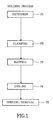
- blow molding comprises the following processes: extruding molten resin through the gap between the extruder die and core to form a parison (P1); clamping the mold around the extruded parison (P2); blowing compressed air into the parison (P3), cooling the molten resin in the mold to solidify it (P4); and opening the mold and removing the molded product thereby obtained (P5).
- P1 parison
- P2 clamping the mold around the extruded parison
- P3 blowing compressed air into the parison
- P4 cooling the molten resin in the mold to solidify it
- P5 opening the mold and removing the molded product thereby obtained
- the invention simulates each of these processes. Namely, data relating to resin properties are prepared (S1) from dynamic viscoelasticity data (D1) and from other physical properties of the resin (D2), and changes in the shape of the molten resin during extrusion (P1) are simulated (S2, hereinafter termed the "extrusion simulation") from this resin properties data and from the molding conditions (D3).
- the extrusion simulation uses the equations for fully-developed flow of a fluid to calculate the flow of the molten resin passing through the gap between the extruder die and core; and after assigning values to the strain of the molten resin when it has passed through this gap, uses the equations for elastic recovery from elongation to calculate the behavior of the molten resin after it has passed through the gap.
- the cooling-thermal deformation simulation is repeated, and the shape that gives the best results is selected.
- the extrusion simulation and the clamping-blowing simulation are used to determine the shape that will give the desired molded product thickness distribution.
- the three molding conditions indicated in Table 1 were employed.
- the outer diameter of the core was 16 mm.
- an oval die of 19.2 mm (a) x 19.0 mm (b) was employed; and
- an oval die of 19.4 mm (a) x 19.0 mm (b) was used, where a and b are defined in FIG. 3.
- the molding cycle was 16.6 seconds, the parison length was 255 mm, the resin temperature was 200 degrees centigrade, and the blowing pressure was 0.57 MPa.
- FIGS. 4A to 4C which also give the simulation results, shown by the solid lines.
- molding conditions A B C die [mm] ⁇ 19.0 19.2 x19.0 19.4 x 19.0 core [mm] ⁇ 16.0 Molding results
- a B C thickness distribution [mm] shown in FIGS. 4A, 4B and 4C container weight [g] 51.17 52.17 53.78 weight of upper flashes [g] 1.94 2.03 2.12 weight of lower flashes [g] 3.21 2.62 2.96
- the shape of the extruder die and core are selected by choosing, from the simulation results shown in FIGS. 4A to 4C, the set of results that approximates to the desired thickness distribution. These are normally chosen so that the thickness of the front, back and sides are approximately equal.
- the shape of the mold cavity is designed so that the targeted molded product shape is obtained when the cooling-thermal deformation is performed on the basis of this thickness distribution.
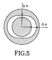
- FIG. 5 shows the configuration of the die and core and the gaps ⁇ a and ⁇ b between them. Gap ⁇ a corresponds to the thickness of the sides of the molded product, while gap ⁇ b corresponds to thickness of the front or back of the molded product.
- FIG. 6 shows the procedure employed to obtain a better die and core shape.
- the extruder die and core that were previously selected are used as the initial shape (S11) and the thickness distribution of the molded product is obtained by extrusion simulation and clamping-blowing simulation (S12).
- the cooling-thermal deformation simulation is then performed using this molded product thickness distribution, and the shape of the molded product after deformation is obtained (S13). It is then decided whether or not the deformation of the molded product is close to a linear deformation (S14). If it is not, and if the front and back of the molded product have expanded relative to the sides, the ratio ⁇ a/ ⁇ b is decreased. On the other hand, if the front and back have sunk in relative to the sides, this ratio is increased (S15). Steps S11 to S15 are then repeated until the deformation approximates to a linear deformation.
- the method for designing molds and extruder dies and cores according to this invention is implemented by the design apparatus depicted in FIG. 7.
- This apparatus comprises extrusion simulation module 1 for simulating the change in shape of the molten resin when a parison is formed by extruding said resin through the gap between the extruder die and core; clamping-blowing simulation module 2 for simulating the change in shape of the molten resin due to clamping the mold around the extruded parison and blowing compressed air into the parison; cooling-thermal deformation simulation module 3 for simulating the thermal deformation that will occur in the molded product due to cooling after the molded product, obtained when the molten resin has solidified in the mold, is removed from the mold in a high-temperature state; and shape design module 4 for determining, from the results of these simulations, the extruder die and core shape that will result in approximately linear thermal deformation, and the mold shape that will give the desired shape of molded product.
- Shape design module 4 designs the shapes of
- This design apparatus also comprises reading device 5, and by reading a program that has been written to a recording medium such as CD-ROM 6 and loading this program into a computer, the computer can be made to operate as a design apparatus for molds, extruder dies and cores according to this invention.
- the relaxation modulus can be calculated for each of the relaxation times set by the designer.
- the full set of data for the physical properties of the resin are then prepared by adding, to the relaxation times and elastic moduli that have been obtained, a parameter indicative of resin nonlinearity.
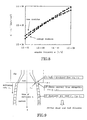
- FIG. 8 which gives an example of how the resin properties data are obtained
- the storage modulus G'( ⁇ ) and loss modulus G"( ⁇ ) can be expressed as follows: where M is the number of relaxation modes. Eleven relaxation modes were adopted in this embodiment.
- the method of least squares was employed to determine the relaxation modulus G j for a given relaxation time ⁇ j .
- the solid lines in FIG. 8 were calculated by substituting the values of ⁇ j and G j obtained in this way into equation (3).
- Parison formation is calculated after combining the molding conditions with the data derived for the physical properties of the resin. This calculation is split into three parts which are applied to different regions, as indicated in FIG. 9. These parts and regions are as follows.
- the FEM data for the parison are prepared from the parison shape and thickness distribution derived as described above, and by combining with data relating to the mold and information relating to how the elements are divided up.
- the clamping-blowing simulation is run on this parison FEM data, after which the cooling-thermal deformation simulation is run.
- this invention enables molds and extruder dies and cores to be designed without trial manufacture.
Landscapes
- Engineering & Computer Science (AREA)
- Manufacturing & Machinery (AREA)
- Mechanical Engineering (AREA)
- Blow-Moulding Or Thermoforming Of Plastics Or The Like (AREA)
- Moulds For Moulding Plastics Or The Like (AREA)
Abstract
Description


| molding conditions | A | B | C |
| die [mm] | 19.0 | 19.2 x19.0 | 19.4 x 19.0 |
| core [mm] | 16.0 |
| Molding results | A | B | C |
| thickness distribution [mm] | shown in FIGS. 4A, 4B and 4C | ||
| container weight [g] | 51.17 | 52.17 | 53.78 |
| weight of upper flashes [g] | 1.94 | 2.03 | 2.12 |
| weight of lower flashes [g] | 3.21 | 2.62 | 2.96 |


Claims (5)
- A method for designing molds, extruder dies and cores, said method comprising:a first step of simulating the change in shape of the molten resin when a parison is formed by extruding said resin through the gap between the extruder die and core;a second step of simulating the change in shape of the molten resin due to clamping the mold around the extruded parison and blowing compressed air into the parison;a third step of simulating the thermal deformation that will occur in the molded product due to cooling after the molded product, obtained when the molten resin has solidified in the mold, is removed from the mold in a high-temperature state; anda fourth step of determining, from the results of the simulations of these first three steps, the shapes of the mold, extruder die and core that will give the desired shape of molded product.
- A method for designing molds, extruder dies and cores claimed in Claim 1, wherein:the first step includes a step for obtaining the parison shape and thickness distribution by assigning values to the shape of the gap between the extruder die and core and to the physical properties of the resin;the second step includes a step for predicting deformation of the parison due to its being clamped and blown, and for obtaining the thickness distribution of the resin after it has been blown against the walls of the mold cavity;the third step includes a step for predicting shrinkage as a function of the thickness distribution obtained; andthe fourth step includes a step for obtaining, from the results of this shrinkage prediction, the mold shape that will give the desired shape of molded product.
- A method for designing molds, extruder dies and cores claimed in Claim 1, wherein:the first step includes a step for obtaining the parison shape and thickness distribution by assigning values to the shape of the gap between the extruder die and core and to the physical properties of the resin;the second step includes a step for predicting deformation of the parison due to its being clamped and blown, and for obtaining the thickness distribution of the resin after it has been blown against the walls of the mold cavity; andthe fourth step includes a step for evaluating, in terms of molded product strength and thermal deformation stability, the thickness distribution of the resin after it has been blown against the walls of the mold cavity, and for obtaining, on the basis of this evaluation, the shape of the extruder die and core that will give the optimum thickness distribution.
- A method for designing molds, extruder dies and cores claimed in Claim 2 or 3, wherein the step for obtaining the parison shape and thickness distribution includes:a step that uses the equations for fully-developed flow of a non-linear viscoelastic fluid to calculate the flow of the molten resin passing through the gap between the extruder die and core; anda step that assigns values to the strain of the molten resin when it has passed through this gap, and uses the equations for elastic recovery from elongation to calculate the behavior of the molten resin after it has passed through the gap.
- An apparatus for designing molds, extruder dies and cores, said apparatus comprising:first means for simulating the change in shape of the molten resin when a parison is formed by extruding said resin through the gap between the extruder die and core;second means for simulating the change in shape of the molten resin due to clamping the mold around the extruded parison and blowing compressed air into the parison;third means for simulating the thermal deformation that will occur in the molded product due to cooling after the molded product, obtained when the molten resin has solidified in the mold, is removed from the mold in a high-temperature state; andfourth means for determining, from the results of the simulations of these first, second and third means, the shapes of the mold, extruder die and core that will give the desired shape of molded product.
Applications Claiming Priority (2)
| Application Number | Priority Date | Filing Date | Title |
|---|---|---|---|
| JP2000062092 | 2000-03-07 | ||
| JP2000062092 | 2000-03-07 |
Publications (2)
| Publication Number | Publication Date |
|---|---|
| EP1134065A2 true EP1134065A2 (en) | 2001-09-19 |
| EP1134065A3 EP1134065A3 (en) | 2003-04-16 |
Family
ID=18582147
Family Applications (1)
| Application Number | Title | Priority Date | Filing Date |
|---|---|---|---|
| EP01105601A Withdrawn EP1134065A3 (en) | 2000-03-07 | 2001-03-06 | Method and apparatus for designing molds, extruder dies and cores |
Country Status (5)
| Country | Link |
|---|---|
| US (1) | US20010028122A1 (en) |
| EP (1) | EP1134065A3 (en) |
| KR (1) | KR20010088405A (en) |
| CN (1) | CN1188265C (en) |
| TW (1) | TWI224546B (en) |
Cited By (2)
| Publication number | Priority date | Publication date | Assignee | Title |
|---|---|---|---|---|
| EP1422037A1 (en) * | 2002-11-20 | 2004-05-26 | Deere & Company | Method for producing rotationally molded parts from semi-crystalline materials |
| CN107808064A (en) * | 2017-11-22 | 2018-03-16 | 武汉理工大学 | The Optimization Design of the short route extrusion forming process of blast-furnace tuyere front end cap body |
Families Citing this family (13)
| Publication number | Priority date | Publication date | Assignee | Title |
|---|---|---|---|---|
| US6627841B2 (en) * | 2001-03-26 | 2003-09-30 | Caterpillar Inc. | Method for designing a weld fixture based on predicted stresses and distortions |
| US7478023B2 (en) * | 2005-05-13 | 2009-01-13 | Seiko Epson Corporation | Coupled algorithms for viscoelastic ink-jet simulations |
| ATE535875T1 (en) * | 2006-09-19 | 2011-12-15 | Japan Steel Works Ltd | DEVICE FOR ESTIMATING VOLATIZATION POWER AND METHOD FOR ESTIMATING VOLATIZATION POWER |
| JP4820318B2 (en) * | 2007-03-22 | 2011-11-24 | 株式会社日立製作所 | Resin molded product design support apparatus, support method, and support program |
| WO2009003677A1 (en) * | 2007-07-02 | 2009-01-08 | Magma Giessereitechnologie Gmbh | Method and apparatus for describing the statistical orientation distribution of particles in a simulation of a mould filling process |
| CN101559634A (en) * | 2008-04-16 | 2009-10-21 | 鸿富锦精密工业(深圳)有限公司 | Setter method of mold core movement |
| CN101966740B (en) * | 2010-09-30 | 2013-06-26 | 凡嘉科技(无锡)有限公司 | Method for molding soft plastic on hard plastic product and mold design method thereof |
| US8668101B2 (en) | 2011-03-23 | 2014-03-11 | Mid-America Machining, Inc. | Method and apparatus for making a light weight container |
| CN102682171B (en) * | 2012-05-15 | 2014-12-31 | 中国电子科技集团公司第五十四研究所 | Method for compensating thermal deformation of mold for high-precision composite material antenna reflector unit |
| CN105599185B (en) * | 2016-03-11 | 2018-06-29 | 武汉华星光电技术有限公司 | A kind of manufacturing method of light-conducting board mold |
| CN114730348B (en) * | 2019-11-26 | 2026-03-03 | 巴斯夫欧洲公司 | Optimization of the geometry of the shaped body and of the production tool |
| US20230114201A1 (en) * | 2021-10-08 | 2023-04-13 | Pepsico, Inc. | Methods for digitally designing preforms and molding instructions for bottles |
| KR102867101B1 (en) * | 2023-11-20 | 2025-10-01 | 한국공학대학교산학협력단 | Extrusion mold shape optimization method |
Family Cites Families (7)
| Publication number | Priority date | Publication date | Assignee | Title |
|---|---|---|---|---|
| JPH05169520A (en) * | 1991-12-25 | 1993-07-09 | Sekisui Chem Co Ltd | Forming process analyzing method in blow forming or vacuum forming |
| JP3233980B2 (en) * | 1992-04-27 | 2001-12-04 | 本田技研工業株式会社 | Blow molding molding control system and molding control method |
| JPH07108595A (en) * | 1993-10-15 | 1995-04-25 | Denki Kagaku Kogyo Kk | Design method of preform or parison shape by blow molding analysis |
| JPH07112481A (en) * | 1993-10-19 | 1995-05-02 | Denki Kagaku Kogyo Kk | Blow Molding Bottle Shape Design Method by Blow Molding Analysis |
| JPH08258128A (en) * | 1995-03-24 | 1996-10-08 | Toray Ind Inc | Mold shape determination method, mold air reservoir position analysis device, mold manufacturing method, molded product manufacturing method, and blow mold molding process analysis device |
| DE69729533T2 (en) * | 1996-04-11 | 2004-11-11 | Kao Corp. | MOLDING TOOL DESIGN, METHOD AND DEVICE |
| US6116888A (en) * | 1998-07-29 | 2000-09-12 | Owens-Brockway Plastic Products Inc. | Prototype mold for blow-molding hollow plastic containers and method of making same |
-
2001
- 2001-03-06 TW TW090105131A patent/TWI224546B/en not_active IP Right Cessation
- 2001-03-06 KR KR1020010011415A patent/KR20010088405A/en not_active Withdrawn
- 2001-03-06 EP EP01105601A patent/EP1134065A3/en not_active Withdrawn
- 2001-03-06 US US09/799,055 patent/US20010028122A1/en not_active Abandoned
- 2001-03-07 CN CNB011109572A patent/CN1188265C/en not_active Expired - Fee Related
Cited By (2)
| Publication number | Priority date | Publication date | Assignee | Title |
|---|---|---|---|---|
| EP1422037A1 (en) * | 2002-11-20 | 2004-05-26 | Deere & Company | Method for producing rotationally molded parts from semi-crystalline materials |
| CN107808064A (en) * | 2017-11-22 | 2018-03-16 | 武汉理工大学 | The Optimization Design of the short route extrusion forming process of blast-furnace tuyere front end cap body |
Also Published As
| Publication number | Publication date |
|---|---|
| TWI224546B (en) | 2004-12-01 |
| CN1188265C (en) | 2005-02-09 |
| EP1134065A3 (en) | 2003-04-16 |
| US20010028122A1 (en) | 2001-10-11 |
| KR20010088405A (en) | 2001-09-26 |
| CN1312153A (en) | 2001-09-12 |
Similar Documents
| Publication | Publication Date | Title |
|---|---|---|
| US20010028122A1 (en) | Method and apparatus for designing molds, extruder dies and cores | |
| EP0844057A1 (en) | Mold designing method and apparatus | |
| Rahmati et al. | Rapid tooling analysis of Stereolithography injection mould tooling | |
| Laroche et al. | Integrated numerical modeling of the blow molding process | |
| JP4125391B2 (en) | Design method of profile extrusion die plate | |
| US9684295B2 (en) | Molding system and method for operating the same | |
| Yang et al. | A non‐isothermal finite element model for injection stretch‐blow molding of PET bottles with parametric studies | |
| KR100611689B1 (en) | Apparatus of aiding design of resin forming products and method thereof | |
| CN109822849A (en) | A molding system and its setting method | |
| JP3650338B2 (en) | Mold design method and apparatus, and extrusion die and core design method and apparatus | |
| US10427344B1 (en) | Molding system for preparing an injection molded fiber reinforced composite article | |
| Debbaut et al. | A comparison between experiments and predictions for the blow molding of an industrial part | |
| Luo et al. | In situ adjustment of a visco hyper elastic model for stretch blow molding process simulation of poly‐ethylene terephthalate bottles | |
| Minh et al. | A study on the welding line strength of composite parts with various venting systems in injection molding process | |
| JP6639899B2 (en) | Molded article design support method, molded article design support apparatus, computer software, storage medium | |
| Hsu et al. | Computer simulation of casting process of aluminium wheels-a case study | |
| JP2955509B2 (en) | Mold design method and apparatus | |
| Battini et al. | Experimental characterisation and modelling of polyethylene terephthalate preform for injection stretch blow moulding | |
| JP2003320577A (en) | Method and apparatus for numerical analysis of blow molding material behavior | |
| CN116011565A (en) | A multi-modal knowledge map construction method and system for extrusion dies | |
| Hioe et al. | A simplified approach to predict part temperature and minimum “safe” cycle time | |
| JP2957503B2 (en) | Mold design method | |
| Suvanjumrat et al. | A novel simulation of bottle blow molding to determine suitable parison thicknesses for die shaping. | |
| JP3107622B2 (en) | Molding process simulation method and apparatus | |
| JPH06126799A (en) | Injection molding process simulation method and apparatus |
Legal Events
| Date | Code | Title | Description |
|---|---|---|---|
| PUAI | Public reference made under article 153(3) epc to a published international application that has entered the european phase |
Free format text: ORIGINAL CODE: 0009012 |
|
| AK | Designated contracting states |
Kind code of ref document: A2 Designated state(s): AT BE CH CY DE DK ES FI FR GB GR IE IT LI LU MC NL PT SE TR |
|
| AX | Request for extension of the european patent |
Free format text: AL;LT;LV;MK;RO;SI |
|
| PUAL | Search report despatched |
Free format text: ORIGINAL CODE: 0009013 |
|
| AK | Designated contracting states |
Designated state(s): AT BE CH CY DE DK ES FI FR GB GR IE IT LI LU MC NL PT SE TR |
|
| AX | Request for extension of the european patent |
Extension state: AL LT LV MK RO SI |
|
| RIC1 | Information provided on ipc code assigned before grant |
Ipc: 7B 29C 49/04 B Ipc: 7B 29C 33/38 B Ipc: 7G 06F 17/50 B Ipc: 7B 29C 45/76 A |
|
| 17P | Request for examination filed |
Effective date: 20030513 |
|
| AKX | Designation fees paid |
Designated state(s): DE FR GB |
|
| 17Q | First examination report despatched |
Effective date: 20040524 |
|
| GRAP | Despatch of communication of intention to grant a patent |
Free format text: ORIGINAL CODE: EPIDOSNIGR1 |
|
| STAA | Information on the status of an ep patent application or granted ep patent |
Free format text: STATUS: THE APPLICATION IS DEEMED TO BE WITHDRAWN |
|
| 18D | Application deemed to be withdrawn |
Effective date: 20051103 |