EP1133403B1 - Motor vehicle fuel tank assembly - Google Patents
Motor vehicle fuel tank assembly Download PDFInfo
- Publication number
- EP1133403B1 EP1133403B1 EP99954231A EP99954231A EP1133403B1 EP 1133403 B1 EP1133403 B1 EP 1133403B1 EP 99954231 A EP99954231 A EP 99954231A EP 99954231 A EP99954231 A EP 99954231A EP 1133403 B1 EP1133403 B1 EP 1133403B1
- Authority
- EP
- European Patent Office
- Prior art keywords
- check valve
- fuel
- tank
- inlet check
- filler pipe
- Prior art date
- Legal status (The legal status is an assumption and is not a legal conclusion. Google has not performed a legal analysis and makes no representation as to the accuracy of the status listed.)
- Expired - Lifetime
Links
- 239000002828 fuel tank Substances 0.000 title claims abstract description 25
- 239000000945 filler Substances 0.000 claims abstract description 45
- 239000000446 fuel Substances 0.000 claims abstract description 31
- 239000007921 spray Substances 0.000 abstract description 3
- OKTJSMMVPCPJKN-UHFFFAOYSA-N Carbon Chemical compound [C] OKTJSMMVPCPJKN-UHFFFAOYSA-N 0.000 description 2
- 229910052799 carbon Inorganic materials 0.000 description 2
- 239000007789 gas Substances 0.000 description 2
- 230000036316 preload Effects 0.000 description 2
- 239000004215 Carbon black (E152) Substances 0.000 description 1
- 229930195733 hydrocarbon Natural products 0.000 description 1
- 150000002430 hydrocarbons Chemical class 0.000 description 1
- 238000007789 sealing Methods 0.000 description 1
Images


Classifications
-
- B—PERFORMING OPERATIONS; TRANSPORTING
- B60—VEHICLES IN GENERAL
- B60K—ARRANGEMENT OR MOUNTING OF PROPULSION UNITS OR OF TRANSMISSIONS IN VEHICLES; ARRANGEMENT OR MOUNTING OF PLURAL DIVERSE PRIME-MOVERS IN VEHICLES; AUXILIARY DRIVES FOR VEHICLES; INSTRUMENTATION OR DASHBOARDS FOR VEHICLES; ARRANGEMENTS IN CONNECTION WITH COOLING, AIR INTAKE, GAS EXHAUST OR FUEL SUPPLY OF PROPULSION UNITS IN VEHICLES
- B60K15/00—Arrangement in connection with fuel supply of combustion engines or other fuel consuming energy converters, e.g. fuel cells; Mounting or construction of fuel tanks
- B60K15/03—Fuel tanks
- B60K15/04—Tank inlets
-
- B—PERFORMING OPERATIONS; TRANSPORTING
- B60—VEHICLES IN GENERAL
- B60K—ARRANGEMENT OR MOUNTING OF PROPULSION UNITS OR OF TRANSMISSIONS IN VEHICLES; ARRANGEMENT OR MOUNTING OF PLURAL DIVERSE PRIME-MOVERS IN VEHICLES; AUXILIARY DRIVES FOR VEHICLES; INSTRUMENTATION OR DASHBOARDS FOR VEHICLES; ARRANGEMENTS IN CONNECTION WITH COOLING, AIR INTAKE, GAS EXHAUST OR FUEL SUPPLY OF PROPULSION UNITS IN VEHICLES
- B60K15/00—Arrangement in connection with fuel supply of combustion engines or other fuel consuming energy converters, e.g. fuel cells; Mounting or construction of fuel tanks
- B60K15/03—Fuel tanks
- B60K15/035—Fuel tanks characterised by venting means
- B60K15/03504—Fuel tanks characterised by venting means adapted to avoid loss of fuel or fuel vapour, e.g. with vapour recovery systems
-
- B—PERFORMING OPERATIONS; TRANSPORTING
- B60—VEHICLES IN GENERAL
- B60K—ARRANGEMENT OR MOUNTING OF PROPULSION UNITS OR OF TRANSMISSIONS IN VEHICLES; ARRANGEMENT OR MOUNTING OF PLURAL DIVERSE PRIME-MOVERS IN VEHICLES; AUXILIARY DRIVES FOR VEHICLES; INSTRUMENTATION OR DASHBOARDS FOR VEHICLES; ARRANGEMENTS IN CONNECTION WITH COOLING, AIR INTAKE, GAS EXHAUST OR FUEL SUPPLY OF PROPULSION UNITS IN VEHICLES
- B60K15/00—Arrangement in connection with fuel supply of combustion engines or other fuel consuming energy converters, e.g. fuel cells; Mounting or construction of fuel tanks
- B60K15/03—Fuel tanks
- B60K15/04—Tank inlets
- B60K15/0406—Filler caps for fuel tanks
- B60K2015/0451—Sealing means in the closure cap
Definitions
- the invention relates to a inlet check valve for use in a fuel tank assembly for motor vehicles according to the preamble of claim 1.
- a typical fuel tank assembly comprises a fuel tank, a filler neck, a filler pipe connecting the filler neck to the fuel tank and an inlet check valve at the base of the filler pipe to prevent a back flow of fuel from the tank through the filler pipe.
- a regular function of the check valve is to prevent blow-back when the fuel tank is being replenished at a fuel filling station and to meet this requirement alone the design can be relatively simple.
- the inlet check valve to remain firmly sealed.
- Document EP-A- 0 714 800 discloses an inlet check valve according to the preamble of claim 1.
- an inlet check valve as defined in claim 1.
- the valve member comprises a plunger.
- the plunger may be substantially coaxial with the filler pipe where it joins the tank.
- the plunger has a head with a profiled surface to deflect fuel towards the discharge orifice.
- the profiled surface is concave.
- the fuel tank assembly may further comprise an auxiliary check valve in or adjacent the inlet check valve and arranged to admit fuel from the filler pipe into the fuel tank at a lower pressure.
- the invention also provides, according to a second aspect, a fuel tank assembly for a motor vehicle and comprising a fuel tank, a filler neck, a filler pipe connecting the filler neck to the fuel tank and an inlet check valve at the lower end of the filler pipe to prevent a back flow of fuel from the tank through the filler pipe, the inlet check valve having a discharge orifice which is normally closed by a valve member which is in use movable against a spring bias by the pressure of fuel in the filler pipe, and an auxiliary check valve in or adjacent the inlet check valve and arranged to admit fuel from the filler pipe into the fuel tank at a lower pressure.
- the auxiliary check valve may be in the valve member, in which case the valve member may incorporate an elastomeric seal.
- the elastomeric seal may seat on a frusto-conical surface of the discharge orifice.
- the auxiliary check valve may comprise a poppet having a head which is spring biased against an auxiliary valve orifice, in which case the auxiliary valve orifice may be in the valve member.
- the poppet head may incorporate an elastomeric seal which may seat on a frusto-conical surface of the auxiliary valve orifice.
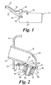
- a motor vehicle fuel tank assembly comprises a fuel tank 11, filler neck 12 and a filler pipe 13 connecting the filler neck to the tank.
- a breather pipe 16 connects an air space above the level of fuel in the fuel tank 11 to the filler neck 12 through a breather check valve 17 and a carbon filter 18.
- the inlet check valve 15 has a discharge orifice 21 which faces towards the base 22 of the tank 11 and this is normally closed by a valve member in the form of a hinged flap 23 which is pivoted at 24 to a support web 25 on the tank 11.
- a hairpin-type spring 26 is provided to spring bias the flap 23 against the discharge orifice 21.
- the interengaging surfaces of the discharge orifice 21 and the hinged flap 23 are frusto-conical and sealed by an elastomeric seal 27.
- the hinged flap 23 incorporates an auxiliary check valve 30 comprising a poppet 28 having a head 29 which is biased against an orifice 31 in the hinged flap 23 by a helical spring 32.
- a helical spring 32 To support the helical spring 32 and provide a guide for the poppet 28, the hinged flap has a flanged boss 33 which is supported by a generally cylindrical portion 34 having apertures 35.
- the interengaging surfaces of the poppet head 29 and the orifice 31 are also frusto-conical and sealed by another elastomeric seal 36.
- the pressure derived from the head of fuel entering the filler pipe 13 through the filler neck 12 acts on the hinged flap 23 so that it pivots against the bias of the hairpin spring 26.
- the lower end 14 of the filler pipe 13 has a profiled wall portion 20 having a generally concave surface so that the flow of incoming fuel is diverted towards the base of the tank in a single stream, particularly under high flow conditions when the flap 23 can move to one side of this stream.
- the hairpin spring 26 has to have a preload which is related to the circumference of the seal. If fuel enters the filler neck 12 at only a slow rate (trickle filling) there may be a tendency for the level of fuel to rise in the filler pipe 13. To prevent this the preload of the helical spring 32 of the auxiliary check valve 30 is considerably lower, this being possible because of the reduced circumference of the seal 36.
- the inlet check valve 115 at the lower end 114 of the filler pipe 113 has a valve member in the form of a plunger 123 which is coaxial with the breather pipe lower end 114.
- the plunger 123 is biased by a helical spring 126 to a position where an end flange 141 abuts a shoulder 142 and the plunger 123 is sealed in the ball of filler pipe lower end 114 by an elastomeric seal 127 to isolate the filler pipe 113 from the interior of the tank 111.
- the plunger 123 has a head 143 having a concave profiled surface 120.
- the pressure derived from the head of fuel entering the filler pipe 113 acts on the plunger 123 to move it against the bias of spring 126 to uncover a discharge orifice 121, fuel from the filler pipe 113 being deflected downwards in a single stream towards the face of the tank 111.
- a rib 143 co-operates with a notch in the flange 141 to provide angular alignment for the profiled head 143.
- the plunger 123 may incorporate an auxiliary valve similar to the auxiliary check valve 30 shown in Fig.2.
- the auxiliary check valve 130 may be in a fixed part of the filler pipe lower end 114 adjacent the inlet check valve 115.
- the inlet check valve 15 shown in Fig.2 may be modified to remove the auxiliary check valve 30 and put it or a functionally similar valve in an adjacent part of the filler pipe lower end 14.
Landscapes
- Engineering & Computer Science (AREA)
- Life Sciences & Earth Sciences (AREA)
- Sustainable Development (AREA)
- Sustainable Energy (AREA)
- Chemical & Material Sciences (AREA)
- Combustion & Propulsion (AREA)
- Transportation (AREA)
- Mechanical Engineering (AREA)
- Cooling, Air Intake And Gas Exhaust, And Fuel Tank Arrangements In Propulsion Units (AREA)
- Check Valves (AREA)
Abstract
Description
Claims (9)
- An inlet check valve (15, 115) arranged in a fuel tank assembly for a motor vehicle, the tank assembly comprising a fuel tank (11, 111), a filler neck (12), a filler pipe (13, 113) connecting the filler neck to the fuel tank, the inlet check valve (15, 115) being arranged at the lower end (14, 114) of the filler pipe to prevent a back flow of fuel from the tank through the filler pipe, the inlet check valve having a discharge orifice (21, 121) which faces towards the base (22) of the tank and which is normally closed by a valve member (23, 123) which is in use movable against a spring bias by the pressure of fuel in the filler pipe, the valve member and the orifice being arranged to divert the flow of incoming fuel towards the base of the tank in a single stream, and wherein the valve member comprises a plunger (123),
characterised in that the plunger has a head (143) with a profiled surface (120) to deflect fuel towards the discharge orifice (121). - An inlet check valve according to claim 1 wherein the plunger (123) is substantially coaxial with the filler pipe (113) where it joins the tank (111).
- An An inlet check valve according to claim 1 or 2 wherein the profiled surface (120) is concave.
- An inlet check valve according to any preceding claim wherein the valve member (123) incorporates an elastomeric seal (127).
- An inlet check valve assembly according to any preceding claim and further comprising an auxiliary check valve in or adjacent the inlet check valve (115) and arranged to admit fuel from the filler pipe (13, 113) into the fuel tank (11) at a lower pressure.
- An assembly according to claim 5 wherein the auxiliary check valve is in the valve member (123).
- An inlet check valve assembly according to claim 5 or 6 wherein the auxiliary check valve comprises a poppet having a head which is spring biased against an auxiliary valve orifice.
- An assembly according to claim 7 wherein the poppet head incorporates an elastomeric seal.
- An assembly according to claim 8 wherein the poppet head elastomeric seal seats on a frusto-conical surface of the auxiliary valve orifice.
Applications Claiming Priority (5)
| Application Number | Priority Date | Filing Date | Title |
|---|---|---|---|
| GB9826072A GB2344086B (en) | 1998-11-28 | 1998-11-28 | Motor vehicle fuel tank assembly |
| GBGB9826074.8A GB9826074D0 (en) | 1998-11-28 | 1998-11-28 | Motor vehicle fuel tank assembly |
| GB9826074 | 1998-11-28 | ||
| GB9826072 | 1998-11-28 | ||
| PCT/GB1999/003770 WO2000032431A1 (en) | 1998-11-28 | 1999-11-11 | Motor vehicle fuel tank assembly |
Publications (2)
| Publication Number | Publication Date |
|---|---|
| EP1133403A1 EP1133403A1 (en) | 2001-09-19 |
| EP1133403B1 true EP1133403B1 (en) | 2004-06-23 |
Family
ID=26314745
Family Applications (1)
| Application Number | Title | Priority Date | Filing Date |
|---|---|---|---|
| EP99954231A Expired - Lifetime EP1133403B1 (en) | 1998-11-28 | 1999-11-11 | Motor vehicle fuel tank assembly |
Country Status (5)
| Country | Link |
|---|---|
| EP (1) | EP1133403B1 (en) |
| AT (1) | ATE269797T1 (en) |
| AU (1) | AU1064400A (en) |
| DE (1) | DE69918328T2 (en) |
| WO (1) | WO2000032431A1 (en) |
Cited By (1)
| Publication number | Priority date | Publication date | Assignee | Title |
|---|---|---|---|---|
| DE102007036112A1 (en) | 2007-08-01 | 2009-02-05 | Bayerische Motoren Werke Aktiengesellschaft | Pressure tank system for motor vehicle i.e. hybrid motor vehicle, has check valve device arranged in filler tube such that device is opened without mechanical contact with pump nozzle during refueling |
Families Citing this family (2)
| Publication number | Priority date | Publication date | Assignee | Title |
|---|---|---|---|---|
| DE10110189B4 (en) | 2001-03-02 | 2009-07-09 | Kautex Textron Gmbh & Co. Kg | Fuel tank |
| DE102010030427A1 (en) * | 2010-06-23 | 2011-12-29 | Robert Bosch Gmbh | Tank for liquids |
Family Cites Families (6)
| Publication number | Priority date | Publication date | Assignee | Title |
|---|---|---|---|---|
| US4974645A (en) * | 1990-01-09 | 1990-12-04 | Ford Motor Company | Non-expulsive fuel filler assembly |
| US5590697A (en) * | 1994-08-24 | 1997-01-07 | G. T. Products, Inc. | Onboard vapor recovery system with two-stage shutoff valve |
| US5568828A (en) * | 1994-11-30 | 1996-10-29 | Stant Manufacturing Inc. | Fuel-delivery control system |
| JP3362594B2 (en) * | 1996-02-29 | 2003-01-07 | トヨタ自動車株式会社 | Automotive fuel storage device |
| US6026853A (en) * | 1997-03-11 | 2000-02-22 | Borg-Warner Automotive, Inc. | Fuel tank filler neck check valve |
| FR2777229B1 (en) * | 1998-04-10 | 2000-06-09 | Plastic Omnium Cie | NON-RETURN VALVE FOR FUEL TANK |
-
1999
- 1999-11-11 WO PCT/GB1999/003770 patent/WO2000032431A1/en not_active Ceased
- 1999-11-11 AT AT99954231T patent/ATE269797T1/en not_active IP Right Cessation
- 1999-11-11 EP EP99954231A patent/EP1133403B1/en not_active Expired - Lifetime
- 1999-11-11 DE DE69918328T patent/DE69918328T2/en not_active Expired - Lifetime
- 1999-11-11 AU AU10644/00A patent/AU1064400A/en not_active Abandoned
Cited By (1)
| Publication number | Priority date | Publication date | Assignee | Title |
|---|---|---|---|---|
| DE102007036112A1 (en) | 2007-08-01 | 2009-02-05 | Bayerische Motoren Werke Aktiengesellschaft | Pressure tank system for motor vehicle i.e. hybrid motor vehicle, has check valve device arranged in filler tube such that device is opened without mechanical contact with pump nozzle during refueling |
Also Published As
| Publication number | Publication date |
|---|---|
| DE69918328D1 (en) | 2004-07-29 |
| WO2000032431A1 (en) | 2000-06-08 |
| AU1064400A (en) | 2000-06-19 |
| DE69918328T2 (en) | 2005-06-23 |
| EP1133403A1 (en) | 2001-09-19 |
| ATE269797T1 (en) | 2004-07-15 |
Similar Documents
| Publication | Publication Date | Title |
|---|---|---|
| JP2626729B2 (en) | Connection tubing for fuel tank filling | |
| US6446826B1 (en) | Seal for filler neck closure assembly | |
| US5868119A (en) | Fuel tank venting system for vehicles | |
| US7182111B2 (en) | Fuel-dispensing nozzle inhibitor | |
| US4501374A (en) | Hazardous fluid tank with check valve | |
| EP2406095B1 (en) | Mis-fuel inhibitor | |
| US6056029A (en) | Fuel-Transfer system | |
| EP1199207A2 (en) | Fuel tank vent control valve | |
| EP2041409B1 (en) | Venting tubing system for a fuel tank | |
| US4989629A (en) | Fuel cut valve for vent line | |
| CN101782159A (en) | Dual Function Valves for Fuel Tanks | |
| US6679396B1 (en) | Redundant seal for tank filler neck closure | |
| SK17193A3 (en) | Check valve | |
| US20030057213A1 (en) | Fuel tank for automobiles | |
| US5924438A (en) | Gas-pressure relief valve unit, particularly for fuel vapors | |
| EP2773523B1 (en) | Filter device and arrangement for ventilating a tank comprising a filter device | |
| US6340093B1 (en) | Fuel tank | |
| KR101486684B1 (en) | Fuel tank for motor vehicles | |
| EP3969313B1 (en) | Capless closure assembly for fuel-tank filler pipe | |
| JPH11147422A (en) | Fuel supply duct for fuel tank | |
| US20020005227A1 (en) | Spring-loaded contaminant cover for tank filler neck closure assembly | |
| US6497335B2 (en) | Filler neck for a fuel tank of a motor vehicle | |
| US6805159B2 (en) | Fuel refilling assembly | |
| EP1133403A1 (en) | Motor vehicle fuel tank assembly | |
| GB2344086A (en) | Fuel tank assembly |
Legal Events
| Date | Code | Title | Description |
|---|---|---|---|
| PUAI | Public reference made under article 153(3) epc to a published international application that has entered the european phase |
Free format text: ORIGINAL CODE: 0009012 |
|
| 17P | Request for examination filed |
Effective date: 20010308 |
|
| AK | Designated contracting states |
Kind code of ref document: A1 Designated state(s): AT BE CH CY DE DK ES FI FR GB GR IE IT LI LU MC NL PT SE |
|
| AX | Request for extension of the european patent |
Free format text: AL;LT;LV;MK;RO;SI |
|
| RAP1 | Party data changed (applicant data changed or rights of an application transferred) |
Owner name: RAVIV PRECISION INJECTION MOLDING Owner name: BAYERISCHE MOTOREN WERKE AKTIENGESELLSCHAFT |
|
| GRAP | Despatch of communication of intention to grant a patent |
Free format text: ORIGINAL CODE: EPIDOSNIGR1 |
|
| GRAS | Grant fee paid |
Free format text: ORIGINAL CODE: EPIDOSNIGR3 |
|
| GRAA | (expected) grant |
Free format text: ORIGINAL CODE: 0009210 |
|
| AK | Designated contracting states |
Kind code of ref document: B1 Designated state(s): AT BE CH CY DE DK ES FI FR GB GR IE IT LI LU MC NL PT SE |
|
| PG25 | Lapsed in a contracting state [announced via postgrant information from national office to epo] |
Ref country code: NL Free format text: LAPSE BECAUSE OF FAILURE TO SUBMIT A TRANSLATION OF THE DESCRIPTION OR TO PAY THE FEE WITHIN THE PRESCRIBED TIME-LIMIT Effective date: 20040623 Ref country code: LI Free format text: LAPSE BECAUSE OF FAILURE TO SUBMIT A TRANSLATION OF THE DESCRIPTION OR TO PAY THE FEE WITHIN THE PRESCRIBED TIME-LIMIT Effective date: 20040623 Ref country code: IT Free format text: LAPSE BECAUSE OF FAILURE TO SUBMIT A TRANSLATION OF THE DESCRIPTION OR TO PAY THE FEE WITHIN THE PRE;WARNING: LAPSES OF ITALIAN PATENTS WITH EFFECTIVE DATE BEFORE 2007 MAY HAVE OCCURRED AT ANY TIME BEFORE 2007. THE CORRECT EFFECTIVE DATE MAY BE DIFFERENT FROM THE ONE RECORDED.SCRIBED TIME-LIMIT Effective date: 20040623 Ref country code: FR Free format text: LAPSE BECAUSE OF FAILURE TO SUBMIT A TRANSLATION OF THE DESCRIPTION OR TO PAY THE FEE WITHIN THE PRESCRIBED TIME-LIMIT Effective date: 20040623 Ref country code: FI Free format text: LAPSE BECAUSE OF FAILURE TO SUBMIT A TRANSLATION OF THE DESCRIPTION OR TO PAY THE FEE WITHIN THE PRESCRIBED TIME-LIMIT Effective date: 20040623 Ref country code: CY Free format text: LAPSE BECAUSE OF FAILURE TO SUBMIT A TRANSLATION OF THE DESCRIPTION OR TO PAY THE FEE WITHIN THE PRESCRIBED TIME-LIMIT Effective date: 20040623 Ref country code: CH Free format text: LAPSE BECAUSE OF FAILURE TO SUBMIT A TRANSLATION OF THE DESCRIPTION OR TO PAY THE FEE WITHIN THE PRESCRIBED TIME-LIMIT Effective date: 20040623 Ref country code: BE Free format text: LAPSE BECAUSE OF FAILURE TO SUBMIT A TRANSLATION OF THE DESCRIPTION OR TO PAY THE FEE WITHIN THE PRESCRIBED TIME-LIMIT Effective date: 20040623 Ref country code: AT Free format text: LAPSE BECAUSE OF FAILURE TO SUBMIT A TRANSLATION OF THE DESCRIPTION OR TO PAY THE FEE WITHIN THE PRESCRIBED TIME-LIMIT Effective date: 20040623 |
|
| REG | Reference to a national code |
Ref country code: GB Ref legal event code: FG4D |
|
| REG | Reference to a national code |
Ref country code: CH Ref legal event code: EP |
|
| REG | Reference to a national code |
Ref country code: IE Ref legal event code: FG4D |
|
| REF | Corresponds to: |
Ref document number: 69918328 Country of ref document: DE Date of ref document: 20040729 Kind code of ref document: P |
|
| PG25 | Lapsed in a contracting state [announced via postgrant information from national office to epo] |
Ref country code: SE Free format text: LAPSE BECAUSE OF FAILURE TO SUBMIT A TRANSLATION OF THE DESCRIPTION OR TO PAY THE FEE WITHIN THE PRESCRIBED TIME-LIMIT Effective date: 20040923 Ref country code: GR Free format text: LAPSE BECAUSE OF FAILURE TO SUBMIT A TRANSLATION OF THE DESCRIPTION OR TO PAY THE FEE WITHIN THE PRESCRIBED TIME-LIMIT Effective date: 20040923 Ref country code: DK Free format text: LAPSE BECAUSE OF FAILURE TO SUBMIT A TRANSLATION OF THE DESCRIPTION OR TO PAY THE FEE WITHIN THE PRESCRIBED TIME-LIMIT Effective date: 20040923 |
|
| PG25 | Lapsed in a contracting state [announced via postgrant information from national office to epo] |
Ref country code: ES Free format text: LAPSE BECAUSE OF FAILURE TO SUBMIT A TRANSLATION OF THE DESCRIPTION OR TO PAY THE FEE WITHIN THE PRESCRIBED TIME-LIMIT Effective date: 20041004 |
|
| PG25 | Lapsed in a contracting state [announced via postgrant information from national office to epo] |
Ref country code: LU Free format text: LAPSE BECAUSE OF NON-PAYMENT OF DUE FEES Effective date: 20041111 Ref country code: IE Free format text: LAPSE BECAUSE OF NON-PAYMENT OF DUE FEES Effective date: 20041111 |
|
| LTIE | Lt: invalidation of european patent or patent extension |
Effective date: 20040623 |
|
| PG25 | Lapsed in a contracting state [announced via postgrant information from national office to epo] |
Ref country code: MC Free format text: LAPSE BECAUSE OF NON-PAYMENT OF DUE FEES Effective date: 20041130 |
|
| NLV1 | Nl: lapsed or annulled due to failure to fulfill the requirements of art. 29p and 29m of the patents act | ||
| REG | Reference to a national code |
Ref country code: CH Ref legal event code: PL |
|
| PLBE | No opposition filed within time limit |
Free format text: ORIGINAL CODE: 0009261 |
|
| STAA | Information on the status of an ep patent application or granted ep patent |
Free format text: STATUS: NO OPPOSITION FILED WITHIN TIME LIMIT |
|
| 26N | No opposition filed |
Effective date: 20050324 |
|
| EN | Fr: translation not filed | ||
| REG | Reference to a national code |
Ref country code: IE Ref legal event code: MM4A |
|
| PG25 | Lapsed in a contracting state [announced via postgrant information from national office to epo] |
Ref country code: PT Free format text: LAPSE BECAUSE OF NON-PAYMENT OF DUE FEES Effective date: 20041123 |
|
| PGFP | Annual fee paid to national office [announced via postgrant information from national office to epo] |
Ref country code: DE Payment date: 20181123 Year of fee payment: 20 |
|
| PGFP | Annual fee paid to national office [announced via postgrant information from national office to epo] |
Ref country code: GB Payment date: 20181130 Year of fee payment: 20 |
|
| REG | Reference to a national code |
Ref country code: DE Ref legal event code: R071 Ref document number: 69918328 Country of ref document: DE |
|
| REG | Reference to a national code |
Ref country code: GB Ref legal event code: PE20 Expiry date: 20191110 |
|
| PG25 | Lapsed in a contracting state [announced via postgrant information from national office to epo] |
Ref country code: GB Free format text: LAPSE BECAUSE OF EXPIRATION OF PROTECTION Effective date: 20191110 |
|
| P01 | Opt-out of the competence of the unified patent court (upc) registered |
Effective date: 20230418 |