EP1133386B1 - Multilayer rolls having a thin fluoropolymer top coat and method of manufacture - Google Patents
Multilayer rolls having a thin fluoropolymer top coat and method of manufacture Download PDFInfo
- Publication number
- EP1133386B1 EP1133386B1 EP98956244A EP98956244A EP1133386B1 EP 1133386 B1 EP1133386 B1 EP 1133386B1 EP 98956244 A EP98956244 A EP 98956244A EP 98956244 A EP98956244 A EP 98956244A EP 1133386 B1 EP1133386 B1 EP 1133386B1
- Authority
- EP
- European Patent Office
- Prior art keywords
- mold
- spider
- roll
- core
- sleeve
- Prior art date
- Legal status (The legal status is an assumption and is not a legal conclusion. Google has not performed a legal analysis and makes no representation as to the accuracy of the status listed.)
- Expired - Lifetime
Links
Images




Classifications
-
- B—PERFORMING OPERATIONS; TRANSPORTING
- B29—WORKING OF PLASTICS; WORKING OF SUBSTANCES IN A PLASTIC STATE IN GENERAL
- B29C—SHAPING OR JOINING OF PLASTICS; SHAPING OF MATERIAL IN A PLASTIC STATE, NOT OTHERWISE PROVIDED FOR; AFTER-TREATMENT OF THE SHAPED PRODUCTS, e.g. REPAIRING
- B29C70/00—Shaping composites, i.e. plastics material comprising reinforcements, fillers or preformed parts, e.g. inserts
- B29C70/68—Shaping composites, i.e. plastics material comprising reinforcements, fillers or preformed parts, e.g. inserts by incorporating or moulding on preformed parts, e.g. inserts or layers, e.g. foam blocks
- B29C70/74—Moulding material on a relatively small portion of the preformed part, e.g. outsert moulding
- B29C70/745—Filling cavities in the preformed part
-
- B—PERFORMING OPERATIONS; TRANSPORTING
- B29—WORKING OF PLASTICS; WORKING OF SUBSTANCES IN A PLASTIC STATE IN GENERAL
- B29C—SHAPING OR JOINING OF PLASTICS; SHAPING OF MATERIAL IN A PLASTIC STATE, NOT OTHERWISE PROVIDED FOR; AFTER-TREATMENT OF THE SHAPED PRODUCTS, e.g. REPAIRING
- B29C45/00—Injection moulding, i.e. forcing the required volume of moulding material through a nozzle into a closed mould; Apparatus therefor
- B29C45/14—Injection moulding, i.e. forcing the required volume of moulding material through a nozzle into a closed mould; Apparatus therefor incorporating preformed parts or layers, e.g. injection moulding around inserts or for coating articles
- B29C45/14467—Joining articles or parts of a single article
- B29C45/14491—Injecting material between coaxial articles, e.g. between a core and an outside sleeve for making a roll
-
- B—PERFORMING OPERATIONS; TRANSPORTING
- B29—WORKING OF PLASTICS; WORKING OF SUBSTANCES IN A PLASTIC STATE IN GENERAL
- B29K—INDEXING SCHEME ASSOCIATED WITH SUBCLASSES B29B, B29C OR B29D, RELATING TO MOULDING MATERIALS OR TO MATERIALS FOR MOULDS, REINFORCEMENTS, FILLERS OR PREFORMED PARTS, e.g. INSERTS
- B29K2083/00—Use of polymers having silicon, with or without sulfur, nitrogen, oxygen, or carbon only, in the main chain, as moulding material
- B29K2083/005—LSR, i.e. liquid silicone rubbers, or derivatives thereof
Definitions
- This invention relates to a method for forming a multilayer roll having a fluoropolymer top layer on an elastic layer which is bonded to a substantially rigid core to an apparatus for fabricating a multi-layer roll with a fluoropolymer top layer formed from a fluoropolymer membrane on an elastomeric base layer bonded to a substantially rigid cylindrical core and to an apparatus for carrying out the method.
- the method of preparation of the roll is particularly well suited for use in xerographic and electrophotographic copying machines and printers.
- rolls used in xerographic copiers and electro graphic printing devices.
- these are fabricated with a solid core or insert and have an intermediate elastomeric base layer covered by a smooth top coat, such as a fluoropolymer top coat.
- the top coat provides an outer surface area of low surface tension. In operations such as fusing, which are generally carried out at elevated temperatures, the low surface tension prevents toner from adhering to the roll surface, or reduced image quality and offset when toner attaches to the roll surface.
- rolls utilized in these devices, include fuser, pressure and donor rolls, film forming and drying rolls in wet or liquid toner systems, corona rolls, squeegee rolls, photoconductor rolls, low friction rolls and printing rolls.
- fuser pressure and donor rolls
- film forming and drying rolls in wet or liquid toner systems
- corona rolls corona rolls
- squeegee rolls photoconductor rolls
- low friction rolls low friction rolls and printing rolls.
- U.S. Patent No. 3,724,983 to Nelson discloses a mold similar to that utilized in Rowland and Tabelle.
- silicone rubber is extruded through a series of ports spaced about a cylindrical core into the space between the core and a flexible sleeve.
- U.S. Patent No. 4,113,825 to Hill, Onnen and Ryder discloses a further embodiment including a plurality of small diameter cylindrical passages for injecting siliconce rubber into the interior of the mold between the sleeve and rigid core.
- Other methods of manufacture include stretching a fluoropolymer sleeve below its yield point and while at this stage, inserting an elastomeric covered roll into the stretched sleeve. Releasing the pressure on the sleeve allows the fluoropolymer sleeve to shrink back and come into complete contact with the roll. In this case, the diameter of the elastomeric roll is larger than the unstretched fluoropolymer sleeve. When a vacuum is used in this process, it provides the added advantage of an air free fluoropolymer/elastomer interface.
- a fluoropolymer powder or latex can be sprayed or coated onto an elastomeric base layer.
- EP-A-0 625 735 to Japan Gore-Tex rolls are provided with a release surface of porous polytetrafluoroethylene top coat in which the pores are impregnated with a cross-linked synthetic rubber over an elastic porous body material of synthetic rubber foam.
- the thickness of the PTFE release surface can be as low as three microns.
- the roll is fabricated by applying a non-continuous adhesive layer on the outer surface of the porous silicone rubber base coat and wrapping a porous expanded PTFE film of about 20 microns thick with a pore size of about two microns, one turn about the silicone rubber foam to form a single layer with a slight edge overlap. The entire assembly is then heated to fuse the adhesives and adhere the pores expanded PTFE film to the silicone rubber.
- Thin films of porous PTFE impregnated with uncured silicone rubber for forming release top coats having thicknesses as low as three microns are also described in European Patent No. EP 441 114 to Fuji Xerox Co., Ltd. and Japan Gore-Tex, Inc.
- unbaked polytetrafluoralethylene is expanded forming a fibrillated polytetrafluoralethylene film with voids ranging from 30 to 98 percent and pores from 0.02 microns to 15 microns is soaked with one or more types of silicone rubber to fill the voids.
- the film is wrapped around the surface of the roll having an elastic body layer and thereafter hardened by heating.
- the object of the invention is to provide a method for preparing a roll having a thin fluoropolymer top layer from a PTFE expanded sheet or tube having a thickness from about 5 to 50 microns (0.2 to 2.0 mil) on an elastomeric base layer bonded to an insert and an apparatus for use in preparing the roll.
- a method for forming a multi-layer roll having a fluoropolymer top layer is formed by disposing a thin porous fluoropolymer membrane in sheet or sleeve form over an elastomeric base layer bonded to a substantially rigid insert is provided.
- the fluoropolymer membrane is formed from an extruded film or a sheet which is stretched in both machine and traverse directions, taken to its melting point and at least partially sintered.
- the fluoropolymer membrane is in th form of a sheet or film, it is wrapped in layers directly over a insert which has been positioned in end spiders with the film wrapped about the insert and extending past the end of the insert to cover the spiders.
- top coat and insert assembly is placed into a concentric thin walled molding sleeve which is then placed into the cavity of a book mold.
- Liquid or flowable solid uncured elastomer material is injected through a spider mounted at the end of the insert into the space between the insert and top coat membrane causing the membrane to expand and fill a tubular mold cavity.
- the elastomeric material is cured.
- the wrapped fluoropolymer layers are compressed creating a continuous covering with no evident seam line.
- the top fluoropolymer layer can be sintered to a desired degree or remain non-sintered.
- a thin flexible non-self supporting extruded tube of fluoropolymer is utilized in place of the wrapped membrane.
- the thin non-self supporting tube is fed over the insert and end spiders extending beyond the length of the insert and spiders.
- the assembled insert and top coat is placed into a tube of a book mold and the uncured elastomeric material is injected between the insert and thin fluoropolymer sleeve expanding and sizing the sleeve to the internal diameter of the tube.
- the elastomeric material is cured, bonding to the insert and the top coat to the cured elastomer.
- the method of fabrication of the roll includes the step of placing the membrane or sleeve over the insert and extending the top coat over the end spiders. This allows injection of resin between the insert and top layer without tearing or wrinkling when injecting the elastomer as the top layer is a non-self supporting sheet or tube. This permits fabrication of rolls having a fluoropolymer top layer as thin as three microns.
- FIGS.1 and 2 show an assembled book mold 11 for the in place molding of a multi-layer roll 12 in accordance with the invention shown in a partial cutaway perspective view in FIG. 2.
- Book mold 11 includes an upper mold section 13 and a mating lower mold section 14 coupled together by a plurality of bolts 16 placed in cooperating holes 17 formed in upper mold section 13 and lower mold section 14.
- the ends of mold 11 include an inlet face plate 18 and an outlet face plate 19 bolted to the ends of upper and lower mold sections 13 and 14 by a plurality of bolts 21 in cooperating holes 22 in face plates 18 and 19.
- a hollow spindle 23 having a threaded nipple 24 is coupled to a source of liquid or flowable uncured elastomerfic material (not shown). Nipple 24 is threaded into a central opening 26 in inlet face plate 18 for injecting the elastomeric resin into mold 11.
- Roll 11 illustrated in FIG. 2 includes a solid core 28 and an elastomeric base layer 29.
- a thin flexible top layer of fluoroelastic polymer 31 is disposed over and completely encloses elastomeric base layer 29.
- Core 28 is a : solid metal core, but may be hollow depending on the applicattion of the finished roll.
- Roll 12 as shown includes a solid metal core (28) and is formed with a large journal 32 at the inlet end of core 28 and a small journal 33 at the opposed outlet end. of core 28. Journals 32 and 33 may be the same or different sizes depending on the use of the finished rolls.
- Top layer 31 is applied in the form of a thin flexible sleeve as described in connection with FIG. 3, or a wrapped film as described in connection with FIG. 4.
- book mold 11 and top layer sleeve 46 are shown in an exploded perspective view. This illustrates the individual components of mold 11 and roll 12 assembled during fabrication.
- Upper mold portion 13 includes an interior cylindrical cavity half 36 and lower mold portion 14 includes a cooperating cylindrical cavity half 37. Mold portions 13 and 14 are assembled to form a hollow cylindrical book mold for receiving a cylindrical sleeve mold 34 with core 288 positioned therein.
- Each mold portion 13 and 14 is formed with a cooperating end seat 38 for forming a cylindrical opening larger in diameter than sleeve mold 34.
- a cylindrical spider collar 39 is mounted in each end seat 38 in upper mold portion 13 and lower mold portion 14.
- Each pair of cylindrical spider collar halves 39 receives a female spider extender 41 with a male spider 42 positioned therein for injecting the elastomeric material about core 28.
- Positioning female spider extenders 41 and 43 between spider collar halves: 39 aids in centering core 28 within the cylindrical cavity in sleeve mold 34. This also retains flexible sleeve 46 of top layer material between the outer cylindrical surface of female spider extenders 41 and 43 and spider seats 38.
- Male inlet spider 42 having a cylindrical base 40 and a conical portion 52 is inserted into female spider extender 41 which is positioned on large journal 32.
- outlet female spider extender 43 receives an outlet male spider 44 which is mounted on small journal 33.
- male inlet spider 42 is positioned over large inlet journal 32, and female inlet spider extender 41 is placed over male inlet spider 42.
- male outlet spider 44 is placed on small outlet journal 33 and placed within female outlet spider extender 43.
- Thin flexible top layer sleeve 46 is then placed over core 28 and the assembled spiders (i.e. male spiders and female spider extenders) mounted on core 28.
- Flexible sleeve 46 is formed in a desired thickness and is dimensioned to have a diameter larger than core 28 and a length sufficient to extend over the full length of an assembly 27 of core 28, male spiders 42 and 44 and female spider extenders 41 and 43 and beyond the ends thereof.
- Sleeve mold 34 is dimensioned to fit into the cylindrical cavity of book mold 11 up against the edge of cylindrical spider collar half 39 and receive core 28 and cylindrical portions 40 of male spiders 42 and 44.
- Flexible elastomeric sleeve 46 is sufficiently long and extends beyond the ends of the respective spiders at each end of core 28. By doing so, this insures that the uncured elastomeric material which is to be forced into the space between sleeve 46 and the outer surface of core 28 will not wrinkle or tear sleeve 46 when the elastomeric material is injected as will be described in connection with FIGS. 5 and 6.
- PTFE membrane 47 is formed from a PTFE : resin which is first mixed with a lubricant then compressed into a pre-form and cold extruded through a sheet die to form a continuous sheet. The continuous sheet is stretched in both the machine and transverse direction and heated to its crystalline melting point. It is then sintered and wound onto supply roll 48.
- Membrane 47 utilized in accordance with the invention vary in pore size which can range from 0.05 to over 3.0 microns.
- PTFE membrane 47 is wrapped in layers directly over assembly 27 of core 28 and sleeve mold 34 with male spiders 42 and 44 mounted on journals 32 and 33, respectively is then inserted into mold 11 for fabrication and curing. After membrane 47 has been wound about core and spider assembly 27 the elements are treated in the same fashion as fabrication utilizing sleeve 46.
- FIGS. 4 and 5 showing injection of elastomeric material is identical regardless of the manner in which the fluoropolymer layer is placed about the assembled core and spider elements. After application of heat and pressure the elastomeric material inside the fluoropolymer top layer material is cured.
- the wrapped layers of PTFE membrane 47 create a continuous covering with no evidence of seam lines.
- Utilizing membrane 47 allows fabricating a fluorocarbon top layer, such as Teflon, with thicknesses from less than 10 microns (0.2 mils) to over 50 microns (2 mils).
- the surface porosity of membrane 47 can be further controlled by sintering and pressuring finished roll 12 after it is removed from the sleeve mold.
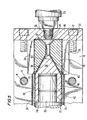
- FIGS. 5 and 6 illustrate in cross-section the large inlet journal end and inlet spider elements of book mold 11.
- the reference numerals are identical to those utilixed in connection with the description of the exploded respective view of FIG. 3.
- male inlet spider 42 is positioned on large journal 32 at the inlet side of core 28.
- Female inlet spider extender 41 is positioned over tapered end 52 of male inlet spider 42 and seated within collar 39 mounted in cylindrical end seat 38 of bottom mold portion 14.
- Flexible sleeve 46 positioned about the assembled spider elements at inlet end of core 28 extends to the inlet side of female inlet spider extender 41. The inlet end of flexible sleeve 46 is tightly held between the cylindrical outer wall of female inlet spider extender 41 and collar 39.
- Male inlet spider 42 is somewhat longer and includes a longer cylindrical opening 51 for receiving longer inlet journal 32.
- the inlet end of male inlet spider 42 includes a tapered surface (52) for mating with an interior tapered opening 53 in female inlet spider extender 41.
- Female inlet spider extender 41 includes a central bore 54 coupled to a funnel inlet 56 which cooperates with nipple 24 of spindle 23 for injecting elastomer material.
- conical end 45 of male spider 42 is formed with a plurality of grooves 57 formed on the outer surface of conical end 52 as shown in FIG.3. At least three or four grooves should be provided, but as many as six or eight may be provided in order to ensure that elastomeric material flows evenly about the entire surface of core 28 causing fluoropolymer top layer sleeve 34 to expand and engage the interior surface of sleeve mold 34.
- fluoropolymer top layer sleeve 46 is placed over spider and core assembly 27 it is inserted into sleeve mold 34 and positioned in bottom mold portion 14, cooperating top mold portion 13 is mounted thereby fully engaging flexible sleeve 46 within spider collar halves 39. Mold 11 is then secured by bolts 16, end plates 18 and 19 are positioned and secured by bolts 21. At this time, nipple 24 is threaded into opening 26 in inlet plate 19. When the assembled sleeve mold 34 is positioned and mold portions 13 and 14 are secured, elastomeric material is then injected into female inlet spider extender 41.
- FIG. 6 shows the identical elements as in FIG. 5; however, elastomeric material 29 can be seen filling the space between flexible sleeve 46 and male inlet spider 42 just as elastomeric material 29 begins to reach the outer surface of core 28. Because the inlet end of sleeve 46 is firmly engaged between the outer surface of female inlet spider extender 41 and the inner cylindrical surface of inlet spider collar halves 39, sleeve 46 retains its smooth profile without being pulled or wrinkled. Elastomeric material 29 is injected until the entire cavity is filled and material is extruded through female outlet spider extender 43 in order to produce roll 11 as shown in FIG.2 and in cross-section in FIG.7.
- Elastomeric material 29 forming the compliant base layer may be a liquid silicone rubber or flowable material in liquid form.
- the viscosity of these materials can vary from a low of 1.0 x 10 4 to as high as 2.5 x 10 5 CPS.
- Elastomeric material 29 is not limited to silicone materials or liquid elastorners . It is possible to utilize mold 11 and prepare multi-layered rolls in accordance with the invention using liquid urethane or other liquid elastomeric materials such as epoxy, polyesters, nitriles and the like.
- Cure temperature for a silicone material is typically from about 135° to 204°C (275° to 400°F).
- the actual cycle time is a function of size, material and configuration.
- FIG. 9 illustrates in plan view a lower multi-cavity mold block 102 having four lower cavities 103.
- a metal core insert 104 with an inlet journal 105 and an outlet journal 106 and a PTFE sleeve 107 thereabout within a sleeve mold 108 is shown seated in each cavity 103 in the same manner as the cavity formed in book mold 11.
- Each cavity 103 in lower mold block 102 has an inlet spider collar 109a and an outlet spider collar 109 fixedly mounted at the inlet and outlet to lower mold block 102, respectively for centering all cylindrical elements.
- An inlet male spider 111 is mounted on inlet journal 105 at the inlet end of insert 104 set within inlet female spider extender 112 which rests within the recess in spider collar 108.
- an outlet male spider 113 is placed on outlet journal 106 of insert 104 and rests within an outlet female spider extender 114 which is seated within recess in outlet spider collar 109.
- PTFE sleeve 107 When assembled in this manner, PTFE sleeve 107 extends beyond both ends of mold sleeve 108, with the ends retained and held securely by the tight fit between the outer cylindrical surface of female spider extenders 112 and 114 and spider collar 109 and 110 in the same manner as the single cavity mold described above. This allows use of an extremely thin and non-self supporting PFTE sleeve which will form outer non-stick top layer 31 of the completed roll 12.
- Elastomer for forming the base coat is feed from the extruder (not shown) through a mold inlet 116 to a main feed block 117 which includes a plurality of inlet channels 118 (shown in phantom) leading to the same number of pneumatic actuated cylinder nozzles 119.
- One nozzle 119 is provided for each cavity 103 at inlet female spider extender 112 which has an inlet channel 121 and an outlet cavity 122 for receivingmale inlet spider 111.
- Female inlet spider extender 112 is formed with a spherical opening 123 on the inlet side to act as a bushing for receiving the sprue end of nozzle 119.
- the outlet end of mold 101 includes male spider 113 mounted on an outlet journal 106 of insert 104 and is disposed within a cavity 124 of female spider extender 114 which is positioned in spider collar 109.
- Each outlet female spider extender 114 includes a bleed cavity 126 with a bleed outlet 127 which is engaged by a bleed hydraulic cylinder 128.
- Cylinders 128 are mounted on a cylinder block 129 and include a cylinder rod 131 with a bleed cylinder rod end 132 with bleed slots 133 which engage bleed outlet 127 of female spider extender 114.
- Each cylinder rod end 132 includes a bleed slot 133 permitting escape of air therethrough.
- Each bleed cavity 126 in female spider extender 114 has a ball bleed element 134 seated therein.
- Elemmant 134 is displaceable within cavity 126 and acts as a seal when the cavity fills with elastomer by closing bleed outlet 127.
- bleed outlet 127 is 0.476 cm (3/16 inch) in diameter
- ball bleed element 134 is 0.635 cm (0.25 inch) in diameter.
- ball element 134 will close the particular cavity.
- bleed slots 133 are expelled through cylinder rod ends 132.
- air continues to be expelled through bleed slots 133 and elastomer reaches bleed ball element 134 in female spider extender 114.
- bleed ball element 134 is forced to the outlet side of bleed cavity 126. This effectively closes bleed outlet 127 of female spider extender 114 and prevents additional elastomer from entering a particular cavity.
- Mold block 102 is mounted on a heated platen (not shown) so that mold sleeves 108 can be heated and cured. Elastomer 116 cures within about 2 to 10 minutes and mold 101 is then released from nozzles 119 and opened to retrieve the completed rolls.
- the sleeve mold part assemblies with insert and siders are cooled, for example, by quenching in cold water, and opened to remove the rolls with sleeves 108.
- the multi-layer inserts 104 are removed, excess top layer and elastomer are trimmed from the ends about journals 105 and 106 to provide a completed multi-layer molded roll as roll 12 in FIG. 2.
- the manufacturing process is completed. If a fibrillated Teflon membrane has been wound about insert 104, the molded roll is generally sintered to complete preparation. Alternatively, sintering can be accomplished prior to trimming the excess coatings about journals 105 and 106. The sintering steps are described in the examples in more detail below.
- the thickness of the base elastomertic coat can vary from 250 microns (10 mil) to 1.25 cm (1/2, inch). The final thickness will depend on the desired end use which is easily obtained by varying the relative dimension of the outer portion of the metal insert and the interior of the cavity of the sleeve mold.
- polytetrafluoralethylene membrane 47 may be sintered or maintained non-sintered.
- the degree of sintering can range from no additional sintering which provides a porous surface to a fully sintered film wherein 99 to 100 percent of the porosity has been eliminated by the process.
- the sintering process entails a combination of subjecting the molded roll to varying degrees of pressure and temperature for a selected period of time.
- FIG. 10 a schematic of a sintering device 151 is illustrated.
- a roll 152 having an outer surface of a membrane 153 which has been formed by injecting elastomeric material and curing is placed into sintering device 151.
- Sintering device 151 includes a series of infrared lamps 154 disposed about the outer surface of roll 152 and includes a pressure roller 156 for applying the desired pressure. During the sintering process, roll 152 is rotated thereby providing pressure evenly about the outer surface of roll 152 as it is rotated to insure uniform heating and sintering of the outer surface 153.
- sintering may utilize a heated drum or roll, rather than sintering lamps.
- infrared lamps 154 are not utilized and drum 156 is a heated drum, generally heated to temperatures of about 475 to 500°C (842 to 932°F). This will provide sufficient heat to sinter the top coat and adjust porosity as desired.
- extruded perfluoroalkxy resin sleeves are used. These PFA sleeves are available in thicknesses raging from 50 to 250 microns (2 to 10 mils).
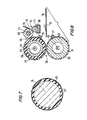
- FIG. 8 is a schematic view illustrating use of a fixing unit 56 prepared in accordance with the invention in a reprographic machine including a hollow fixing roll 57 having an elastomeric base coat 58 on a hollow insert.
- a pressure roll 61 which rotates in contact with fixing roll 57 was prepared by coating a PTFE film 62 on the surface of a metal core 63.
- Both rolls 57 and 61 are hollow and provided with heat sources such as infrared lamps 64 and 66, respectively, on the inside thereof.
- An oil feeding unit 67 is utilized to prevent toner offset by providing oil from an oil pan 68 to an oil coating roll 69 via an oil pick up roll 71.
- Oil coating roll 69 has a metal core 72 coated with a silicone rubber coating 73 on the outside thereof.
- Oil coating roll 69 provides a constant amount of oil to fixing roll 57.
- Oil feeding unit 67 includes a blade member 74.
- Fixing unit 56 includes whipping devices 76 and 77 which clean rolls 57 and 61 at a copy medium 78 having an image 79 thereon is fed between fixing roll 57 and pressure roll 61.
- Book mold 11 in FIG. 3 includes a single mold sleeve 46. This has been set forth for purposes of illustration only and not by way of limitation. During commercial production of rolls 12 book molds including a plurality of molding cavities 103 as shown in FIG. 9 for receiving a plurality of molding sleeves and corresponding seats are used. This will permit formation of several rolls from a single injection of elastomeric material and a single cure cycle of a book mold having multiple cavities for receiving a plurality of sleeve molds.
- fabricating a multi-layer roll having a thin non-stick top layer on an elastomeric baselayer in accordance with the invention is a one step process.
- the multi-layer roll construction uses a fluoropolymer film in sheet form or sleeve form. This allows molding in place with an elastomeric material injected between the outer layer and a metal insert.
- a concentric tube as the mold allows accurate positioning of the core and elastomeric and top layers as they are retained in the molding sleeve within a book mold enclosure.
- the method in accordance with the invention provides a one step process for molding in place.
- the thin top layer sleeve or membrane is held by a spider upstream of the point of elastomer injection, tearing or wwrinkling of the thin top layer film is avoided.
- a wide variety of sizes, thickness of base layer and top layer are also obtainable. There is a wide range of flexibility in controlling the film thickness as well as providing a low cost fabrication technique.
- ingredients or compounds recited in the singular are intended to include compatible mixtures of such ingredients wherever the sense permits.
Landscapes
- Engineering & Computer Science (AREA)
- Mechanical Engineering (AREA)
- Chemical & Material Sciences (AREA)
- Composite Materials (AREA)
- Manufacturing & Machinery (AREA)
- Rolls And Other Rotary Bodies (AREA)
- Casting Or Compression Moulding Of Plastics Or The Like (AREA)
Description
| Example of Partially Sintered Roller: | |
| Rubber: | Silicone 50 Shore A |
| Toplayer: | 25 micron fibrillated PTFE |
| Load on roll: | 0.18 kg per linear cm (15 lbs per linear inch) |
| Temperature-preheat °C (°F) | 218-232 (425-450) |
| Sintering temperature: °C (°F) | 330-343 (625-650) |
| Time: | 120-240 secs. |
| Example of Fully Sintered Roller: | |
| Rubber: | Silicone 50 Shore A |
| Toplayer: | 25 micron fibrillated PTFE |
| Load on roll: | 0.18 kg per linear cm (15 lbs per linear inch) |
| Temperature-preheat °C (°F) | 218-232 (425-450) |
| Sintering temperature: °C (°F) | 343-413 (650-775) |
| Time: | 240-360 secs. |
Claims (10)
- A method for forming a multi-layer roll having a fluoropolymer top layer (31) on an elastic layer (29) which is bonded to a substantially rigid core (28), comprising:providing a substantially rigid cylindrical core (28) and disposing a layer of flexible non-self-supporting fluoropolymer (31) around the cylindrical core (28) to form said top layer (31) in sheet or sleeve form over the full length of the core (28) to form an assembly;placing said assembly into a cylindrical mold sleeve (34) having an inlet end and an outlet end together with a spider assembly (41, 42) at at least the inlet end of the core (28) for directing flowable elastomeric material (29) between the top layer (31) and the core (28), with the ends of the top layer (31) extending beyond the ends of the mold sleeve (34) and the spider assembly (41, 42);placing the mold sleeve (34) with the core assembly into the cavity (36, 37) of a book mold (11) and closing the book mold (11) so that the top layer (31) that extends beyond the ends of the mold sleeve (34) and the spider assembly (41, 42) is engaged between the spider assembly (41, 42) and the book mold cavity (36, 37);injecting flowable elastomeric material (29) between the top layer (31) and core (28) at a location downstream of the engagement of at least the inlet end of the top layer (31);heating the book mold (11) to cure the elastomeric material (29);cooling the molded insert; andremoving the multi-layer roll from the mold sleeve (34).
- The method for forming a multi-layer roll of claim 1, wherein the top layer (31) is a flexible extruded fluoroelastomer film and the method includes wrapping the film about the core (28).
- The method for forming a multi-layer roll of claim 1, wherein the top layer (31) is a flexible non-self supporting sleeve and the method includes disposing the sleeve about the core (28) and the spider assembly (41, 42) which extends beyond the mold sleeve (34) so that the flexible sleeve is engaged between the outside of the spider assembly (41, 42) and the book mold cavity.
- The method for forming a multi-layer roll of claim 1, further including the step of sintering the top layer (31) by applying heat and pressure to the roll.
- An apparatus for fabricating a multi-layer roll with a fluoropolymer top layer (31) formed from a fluoropolymer membrane on an elastomeric base layer (29) bonded to a substantially rigid cylindrical core (28) comprising:a book mold (11) having a bottom section (14) and cooperating upper section (13) for forming a cylindrical cavity having an inlet end and an outlet end when the mold is closed;a cylindrical mold sleeve (34) adapted to seat within the cylindrical cavity of the assembled mold;a spider assembly (41, 42) for directing injected flowable elastomer material into the roll assembly between the core (28) and top layer (31) positioned on the inlet end of the mold sleeve (34);the mold cavity including a region for engaging the top layer (31) between the spider assembly (41, 42) and the mold cavity when the sleeve is placed in the mold;a source of elastomeric material for injection into the roll assembly; andmeans for heating the mold to cure the elastomeric material.
- The apparatus for fabricating a multi-layer roll of claim 5, wherein the spider assembly (41, 42) includes a male spider (42) adapted to be mounted on the end of the core (28) having a cylindrical portion and a tapered conical portion, the tapered portion including channels extending from the end of the conical portion to the cylindrical position, and a female spider extender (41) including a central opening for feeding elastomeric material to the conical portion of the male spider (42) and a tapered opening for receiving the conical portion of the male spider (42) and having an outer cylindrical wall engaging the membrane with the mold sleeve in place.
- The apparatus for fabricating a multi-layer roll of claim 5, further including means for bleeding (127) excess elastomeric material at the mold outlet which includes a bleed element having a dimension greater than the channel adapted to be displaced in the channel when the mold is full to permit bleeding of elastomer to prevent additional elastomer to the mold cavity.
- An apparatus for carrying out a method according to claim 1 for fabricating a plurality of multi-layer rolls with a fluoropolymer top layer (31) on an elastomeric base layer (29) bonded to a substantially rigid cylindrical core (28), comprising:a plurality of cylindrical mold sleeves (34);a book mold (11) having a bottom section (14) and cooperating upper section (13) for forming a plurality of cylindrical cavities for receiving the mold sleeves (34) when the mold is closed, each cavity adapted to receive and centre a roll insert disposed within the sleeves and securely engage the top layer (31) about the insert and extending beyond the ends of the mold sleeves (34);the mold formed with an inlet (26) for injecting elastomeric material (29) into the roll assemblies;means mounted on one end of the mold for injecting flowable elastomeric material into the roll assembly between the inner cylindrical core (28) and top layer (31) in a cylindrical mold sleeve (34) positioned in the cavity; andmeans for heating the mold to cure the elastomeric material.
- The apparatus for fabricating a multi-layer roll of claim 8, wherein the means for directing elastomeric material between the core and top layer is a substantially cylindrical spider assembly (41, 42) having channels for distributing the elastomeric material about the core.
- The apparatus for fabricating a multi-layer roll of claim 9, wherein the spider assembly includes a male spider (42) adapted to be mounted on the end of the core (28) having a cylindrical portion and a tapered conical portion, the tapered portion including channels extending from the end of the conical portion to the cylindrical position. and a female spider extender (41) including a central opening for feeding elastomeric material to the tapered conical position of the male spider (42) and a tapered opening for receiving the conical portion of the male spider (42) and having an outer cylindrical wall for engaging the membrane with the mold cavity when the mold is closed.
Applications Claiming Priority (3)
| Application Number | Priority Date | Filing Date | Title |
|---|---|---|---|
| US959397 | 1997-10-28 | ||
| US08/959,397 US6168751B1 (en) | 1997-10-28 | 1997-10-28 | Method of making multilayer rolls having a thin fluoropolymer top coat |
| PCT/US1998/022752 WO2000024561A1 (en) | 1998-10-25 | 1998-10-28 | Multilayer rolls having a thin fluoropolymer top coat and method of manufacture |
Publications (2)
| Publication Number | Publication Date |
|---|---|
| EP1133386A1 EP1133386A1 (en) | 2001-09-19 |
| EP1133386B1 true EP1133386B1 (en) | 2005-06-01 |
Family
ID=56289868
Family Applications (1)
| Application Number | Title | Priority Date | Filing Date |
|---|---|---|---|
| EP98956244A Expired - Lifetime EP1133386B1 (en) | 1997-10-28 | 1998-10-28 | Multilayer rolls having a thin fluoropolymer top coat and method of manufacture |
Country Status (1)
| Country | Link |
|---|---|
| EP (1) | EP1133386B1 (en) |
Cited By (1)
| Publication number | Priority date | Publication date | Assignee | Title |
|---|---|---|---|---|
| CN110325609A (en) * | 2017-02-15 | 2019-10-11 | 琳得科株式会社 | The manufacturing method of roller and roller |
-
1998
- 1998-10-28 EP EP98956244A patent/EP1133386B1/en not_active Expired - Lifetime
Cited By (2)
| Publication number | Priority date | Publication date | Assignee | Title |
|---|---|---|---|---|
| CN110325609A (en) * | 2017-02-15 | 2019-10-11 | 琳得科株式会社 | The manufacturing method of roller and roller |
| CN110325609B (en) * | 2017-02-15 | 2021-08-17 | 琳得科株式会社 | Roll and roll manufacturing method |
Also Published As
| Publication number | Publication date |
|---|---|
| EP1133386A1 (en) | 2001-09-19 |
Similar Documents
| Publication | Publication Date | Title |
|---|---|---|
| US6168751B1 (en) | Method of making multilayer rolls having a thin fluoropolymer top coat | |
| US5944930A (en) | Method of manufacturing tubular film | |
| JP3406110B2 (en) | Method of manufacturing roller coated with silicone-based elastic material layer, manufacturing machine for implementing the method, and cylindrical support structure used for implementing the method | |
| US7285177B2 (en) | Thin-walled reinforced sleeve with integral compressible layer | |
| US20030062644A1 (en) | Polytetrafluoroethylene film and manufacture of same | |
| US6141873A (en) | Method of manufacture of multi-layer roll having compliant PTFE top layer from a fibrillated PTFE membrane | |
| US20020002920A1 (en) | Variable-format web-fed offset printing machine and method of producing variable-format surfaces | |
| CA2402715A1 (en) | Apparatus and process for making prosthetic suction sleeve | |
| CA1311595C (en) | Process and equipment for making composite tubes | |
| CA1160012A (en) | Extruder heads for continuous manufacture of impermeable reinforced tubing particularly hose | |
| KR20020070967A (en) | Seamed sleeved blanket and method for making and using same | |
| CZ293384B6 (en) | Method and apparatus of manufacturing synchronous drive belt | |
| EP1133386A1 (en) | Multilayer rolls having a thin fluoropolymer top coat and method of manufacture | |
| KR930005327B1 (en) | Rubber tube manufacturing method and resin coating device used therein | |
| WO2000024561A1 (en) | Multilayer rolls having a thin fluoropolymer top coat and method of manufacture | |
| US7334336B2 (en) | Method for producing a sleeved polymer member, an image cylinder or a blanket cylinder | |
| US6902640B2 (en) | Method for manufacturing a belt | |
| JP3066115B2 (en) | Roller manufacturing equipment | |
| US20050137071A1 (en) | Plastic sleeve for an image cylinder and a method for producing the plastic sleeve | |
| JP2991340B2 (en) | Manufacturing method of multilayer structure roller | |
| JP2002316335A (en) | Rubber roll manufacturing method | |
| JP4829608B2 (en) | Method for producing semiconductive seamless belt | |
| US20050143240A1 (en) | Polymer sleeve member for an image cylinder or a blanket cylinder | |
| JP2012163829A (en) | Roller for fixing device, manufacturing method of the same, fixing device, and image formation apparatus | |
| US6103038A (en) | Method of coating fusing members used in xerographic printing |
Legal Events
| Date | Code | Title | Description |
|---|---|---|---|
| PUAI | Public reference made under article 153(3) epc to a published international application that has entered the european phase |
Free format text: ORIGINAL CODE: 0009012 |
|
| 17P | Request for examination filed |
Effective date: 20000524 |
|
| AK | Designated contracting states |
Kind code of ref document: A1 Designated state(s): BE GB NL |
|
| 17Q | First examination report despatched |
Effective date: 20010920 |
|
| GRAP | Despatch of communication of intention to grant a patent |
Free format text: ORIGINAL CODE: EPIDOSNIGR1 |
|
| GRAS | Grant fee paid |
Free format text: ORIGINAL CODE: EPIDOSNIGR3 |
|
| GRAA | (expected) grant |
Free format text: ORIGINAL CODE: 0009210 |
|
| AK | Designated contracting states |
Kind code of ref document: B1 Designated state(s): BE GB NL |
|
| REG | Reference to a national code |
Ref country code: GB Ref legal event code: FG4D |
|
| PGFP | Annual fee paid to national office [announced via postgrant information from national office to epo] |
Ref country code: NL Payment date: 20051031 Year of fee payment: 8 |
|
| PGFP | Annual fee paid to national office [announced via postgrant information from national office to epo] |
Ref country code: BE Payment date: 20051215 Year of fee payment: 8 |
|
| PLBE | No opposition filed within time limit |
Free format text: ORIGINAL CODE: 0009261 |
|
| 26N | No opposition filed |
Effective date: 20060302 |
|
| PG25 | Lapsed in a contracting state [announced via postgrant information from national office to epo] |
Ref country code: NL Free format text: LAPSE BECAUSE OF NON-PAYMENT OF DUE FEES Effective date: 20070501 |
|
| GBPC | Gb: european patent ceased through non-payment of renewal fee |
Effective date: 20061028 |
|
| NLV4 | Nl: lapsed or anulled due to non-payment of the annual fee |
Effective date: 20070501 |
|
| PG25 | Lapsed in a contracting state [announced via postgrant information from national office to epo] |
Ref country code: GB Free format text: LAPSE BECAUSE OF NON-PAYMENT OF DUE FEES Effective date: 20061028 |
|
| BERE | Be: lapsed |
Owner name: *AMES RUBBER CORP. Effective date: 20061031 |
|
| REG | Reference to a national code |
Ref country code: GB Ref legal event code: S28 |
|
| REG | Reference to a national code |
Ref country code: GB Ref legal event code: S28 Effective date: 20081118 |
|
| PG25 | Lapsed in a contracting state [announced via postgrant information from national office to epo] |
Ref country code: BE Free format text: LAPSE BECAUSE OF FAILURE TO SUBMIT A TRANSLATION OF THE DESCRIPTION OR TO PAY THE FEE WITHIN THE PRESCRIBED TIME-LIMIT Effective date: 20061031 |
|
| PGFP | Annual fee paid to national office [announced via postgrant information from national office to epo] |
Ref country code: GB Payment date: 20171027 Year of fee payment: 20 |
|
| REG | Reference to a national code |
Ref country code: GB Ref legal event code: PE20 Expiry date: 20181027 |
|
| PG25 | Lapsed in a contracting state [announced via postgrant information from national office to epo] |
Ref country code: GB Free format text: LAPSE BECAUSE OF EXPIRATION OF PROTECTION Effective date: 20181027 |