EP1133211A2 - Information apparatus having speakers - Google Patents
Information apparatus having speakers Download PDFInfo
- Publication number
- EP1133211A2 EP1133211A2 EP01301842A EP01301842A EP1133211A2 EP 1133211 A2 EP1133211 A2 EP 1133211A2 EP 01301842 A EP01301842 A EP 01301842A EP 01301842 A EP01301842 A EP 01301842A EP 1133211 A2 EP1133211 A2 EP 1133211A2
- Authority
- EP
- European Patent Office
- Prior art keywords
- signal
- amplifier
- information apparatus
- speakers
- power
- Prior art date
- Legal status (The legal status is an assumption and is not a legal conclusion. Google has not performed a legal analysis and makes no representation as to the accuracy of the status listed.)
- Granted
Links
Images


Classifications
-
- H—ELECTRICITY
- H04—ELECTRIC COMMUNICATION TECHNIQUE
- H04R—LOUDSPEAKERS, MICROPHONES, GRAMOPHONE PICK-UPS OR LIKE ACOUSTIC ELECTROMECHANICAL TRANSDUCERS; DEAF-AID SETS; PUBLIC ADDRESS SYSTEMS
- H04R5/00—Stereophonic arrangements
- H04R5/04—Circuit arrangements, e.g. for selective connection of amplifier inputs/outputs to loudspeakers, for loudspeaker detection, or for adaptation of settings to personal preferences or hearing impairments
-
- H—ELECTRICITY
- H04—ELECTRIC COMMUNICATION TECHNIQUE
- H04R—LOUDSPEAKERS, MICROPHONES, GRAMOPHONE PICK-UPS OR LIKE ACOUSTIC ELECTROMECHANICAL TRANSDUCERS; DEAF-AID SETS; PUBLIC ADDRESS SYSTEMS
- H04R2420/00—Details of connection covered by H04R, not provided for in its groups
- H04R2420/05—Detection of connection of loudspeakers or headphones to amplifiers
Definitions
- the present invention relates an information apparatus having a self-diagnosis function. More particularly, the present invention relates an information apparatus provided with speakers which has a function of automatically detecting whether or not the speakers are connected to the amplifiers.
- a self-diagnosis function is normally incorporated into a navigation system, by which it is judged whether or not a GPS antenna, beacon or gyroscope unit is connected to a system body, and also a self-diagnosis function is normally incorporated into a navigation system, by which it is judged whether or not a vehicle speed pulse is inputted into the system body.
- the present invention has been accomplished in view of the above problems, and therefore an object of the present invention to provide an information apparatus having speakers capable of making a self-diagnosis with a simple structure of the information apparatus itself whether or not an amplifier is connected with a speaker.
- an information apparatus having speakers comprising: an amplifier; a speaker connected to the amplifier; an input means for inputting a predetermined inspection signal into the amplifier; and a connection judgment means for judging whether or not the speaker is connected to the amplifier according to a signal to be inspected which is generated when the inspection signal is inputted.
- the input means successively inputs an inspection signal into a plurality of speakers connected to the amplifier.
- the inspection signal is composed of a frequency component out of the audible frequency band of human or a frequency component out of the audible frequency band of human close to the audible frequency.
- the signal to be inspected is extracted from a power supply line inputted into the amplifier.
- the signal to be inspected is a ripple component
- the connection judgment means detects a signal level of the ripple component
- an information apparatus having speakers comprising: an amplifier mounted on a moving body and a speaker connected to the amplifier; an input means for inputting a predetermined inspection signal into the amplifier at the start of the moving body; and a connection judgment means for judging whether or not the speaker is connected to the amplifier according to a signal to be inspected which is generated when the inspection signal is inputted.
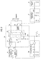
- FIG. 1 is a block diagram in the case where the information apparatus 100 is used as an apparatus mounted on a vehicle which is a moving body.
- the information apparatus 100 includes: four speakers FLS, FRS, RLS, RRS arranged on the right and left in the front and on the right and left at the rear; four power ICs 10a to 10d for driving the above four speakers FLS, FRS, RLS, RRS; four extracting circuits 20a to 20d connected to the ripple terminals 13a to 13d of power ICs 10a to 10d for extracting a ripple component (a signal to be inspected which will be described later); an input switch circuit 22 which is an input means for inputting a signal (an inspection signal which will be described later) into the input terminals 14a to 14d of power ICs 10a to 10d; a microcomputer 23 which is a connection judgment means for judging whether or not speakers FLS, FRS, RLS, RRS are connected to amplifiers 12a to 12d according to the output voltages of the extraction circuits 20a to 20d; ROM 24 in which an operation program of the microcomputer 23 is previously stored; a display section 25 for displaying a message; a battery
- Four power ICs 10a to lOd have the same circuit and respectively accommodate electronic volume controls lla to 11d and amplifiers 12a to 12d for amplifying electric power and respectively have the ripple terminals 13a to 13d.
- the electronic volume controls 11a to 11d of the power ICs 10a to 10d are respectively controlled by the microcomputers 23. Electric power is supplied from the battery 26 through the power supply circuit 27 to the four power ICs 10a to 10d via the electric power terminals 18a to 18d which are individually provided.
- the extracting circuits 20a to 20d connected to the ripple terminals 13a to 13d are respectively composed of the same circuit, and the output voltage is supplied to the microcomputer 23.
- an inspection signal is used as a signal to be inputted into the input terminal 14a to 14d of each power IC 10a to 10d.
- the frequency of this inspection signal is in a range from 20 to 50 kHz which is out of the audible frequency band of human so that a sound given by speaker FLS can not be heard by a user during the process of self-diagnosis.
- this inspection signal is a rectangular waveform signal, the frequency of which is 30 kHz, which is generated by an oscillating circuit composed in the microcomputer 23.
- the reason why this inspection signal is a rectangular waveform signal is that the rectangular waveform signal can be simply created by the microcomputer 23. Even if a sine wave is used for the inspection signal, the same effect, which will be described later, can be provided.
- the signal to be inspected represents a ripple component outputted into each ripple terminal 13a to 13d originated from the inspection signal inputted into each power IC 10a to 10d.
- the information apparatus 100 makes a self-diagnosis as follows.
- the signal to be inspected which is generated (leaking out) in the ripple terminal 13a to 13d of each power IC 10a to 10d, is extracted by each extracting circuit 20a to 20d, and it is diagnosed by the output voltage of each extracting circuit 20a to 20d whether or not speaker FLS, FRS, RLS, RRS is connected to each amplifier 12a to 12d.
- Figs. 2 and 3 this operation will be explained in detail. In this connection, Fig.
- FIG. 2 is a view showing the circuit structure of the primary portion of power IC 10a for driving front left speaker FLS, which is one of the four power ICs 10a to 10d composing the information apparatus 100, and also showing the battery 26 and the power supply circuit 27.
- Fig. 3 is a view for explaining the operation of the extracting circuit 20a. In addition to Fig. 2, Fig. 3 shows the input switch circuit 22 for switching an inspection signal supplied from the microcomputer 23 and also shows the extracting circuit 20a for extracting a signal to be inspected.
- electric power is supplied to power IC 10a from the battery 26 via the power supply circuit 27.
- voltage Vcc which is a supply voltage
- the amplifier 12a usually has normal signal input terminal IN and reference voltage terminal REF, and a signal sent from the electronic volume control lla is supplied to signal input terminal IN.
- a voltage obtained when voltage Vcc is divided by resistance is supplied to reference voltage terminal REF, and this reference voltage terminal REF is connected to the ripple terminal 13a. Since it is necessary to supply reference DC voltage to reference voltage terminal REF, the ripple terminal 13a of power IC 10a is provided for the object of connecting smoothing condenser Cr for removing the ripple components from the power supply circuit 27.
- a signal inputted from the input terminal 14a is supplied to the amplifier 12a via the electronic volume control lla, so that speaker FLS connected to the amplifier 12a can be driven.
- the amplifier 12a supplies a drive current via the power supply terminal 18a, output terminal 16a, speaker FLS and output terminal 17a.
- an intensity of the output signal is increased so that an intensity of the drive current of the amplifier 12 is increased, an electric current corresponding to the drive current of the amplifier 12a is supplied from the power supply terminal 18a. Due to the foregoing, speaker FLS is capable of outputting a signal of high intensity.
- the drive impedance of the power supply circuit 27 is zero and the output impedance is infinite, it is possible for the power supply circuit 27 to stably supply an electric current with respect to the drive circuit of power IC 10a, however, since the power supply circuit 27 is connected to the battery 26 by a long wiring (power supply line), the power supply impedance of the electric power line containing the battery 26 is increased. In this case, a slight voltage fluctuation is caused in voltage Vcc of power IC 10a corresponding to the drive current of the amplifier 12a.
- the ripple terminal 13a of power IC 10a creates a reference voltage by dividing voltage Vcc with resistance, however, when a voltage fluctuation is caused in voltage Vcc, a ripple component, which can not be completely removed by smoothing condenser Cr, is outputted from the ripple terminal 13a.
- This ripple component is originated from the signal inputted into the amplifier 12a, and the amplitude of the ripple component corresponds to an intensity of the drive current. That is, for example, when 1 kHz is supplied to the amplifier 12a, a waveform, which is obtained when 1 kHz is smoothened, is outputted.
- the intensity of the drive current is high, the ripple component is large, and when the intensity of the drive current is low, the ripple component is small.
- the ripple component outputted to the ripple terminal 13a in the case of breaking of wire or disconnection of speaker FLS connected to the output terminals 16a, 17a of power IC 10a, even when an input signal of high intensity is supplied to power IC 10a, a drive current of high intensity does not flow in speaker FLS. Therefore, the ripple component is reduced. That is, when the signal outputted to the ripple component 13a of power IC 10a is precisely extracted and the thus extracted signal level is monitored, it is possible to judge whether or not breaking of wire is caused in speaker FLS or whether or not disconnection is caused in speaker FLS. Therefore, in the information apparatus 100 of the present invention, the signal outputted to the ripple terminal 13a can be precisely extracted by using the extracting circuit 20a shown in Fig. 3.
- the extracting circuit 20a includes: an amplifier 21, connection condenser C1, diode D for detection, and high frequency filters C2, R2.
- the amplifier 21 is connected to the ripple terminal 13a, and an output of the extracting circuit 20 is sent to the microcomputer 23.
- the electronic volume control 11a is set at a rated volume position by the microcomputer 23.
- a signal of rated electric power is outputted into speaker FLS.
- a signal to be inspected is outputted into the ripple terminal 13a of power IC 10a.
- a signal level of the signal to be inspected at the time of rating, which is outputted into the ripple terminal 13a is approximately 50 mVP-P.
- a signal to be inspected which is outputted from the ripple terminal 13a of power IC 10a, is amplified by the amplifier 21, and the thus amplified signal is subjected to amplitude detection by diode D. After that, a high frequency component is removed from the signal by high frequency filter C2, R1. In this way, the signal which is in a state of DC voltage is supplied to the microcomputer 23.
- the signal to be inspected of the ripple terminal 13a is subjected to amplitude detection. Therefore, when a signal level of the signal to be inspected is high, a high DC voltage is outputted, and when a signal level of the signal to be inspected is low, a low DC voltage is outputted.
- the microcomputer 23 is capable of clearly distinguishing the DC voltage, which is outputted from the extracting circuit 20a when a rated input is supplied to the input terminal 14a of power IC 10a, from the DC voltage which is outputted from the extracting circuit 20a when breaking of wiring or disconnection is caused in speaker FLS. Therefore, for example, when a threshold value is provided for the DC voltage outputted from the extracting circuit 20a, and when the DC voltage is not less than the predetermined threshold value, it can be judged that speaker FLS is normally connected, and when the DC voltage is lower than the predetermined threshold value, it can be judged that breaking of wiring or disconnection is caused in speaker FLS.
- the information apparatus 100 to make a self-diagnosis of whether or not the amplifiers 12a to 12d are respectively connected to speakers FLS, FRS, RLS, RRS when the DC voltages outputted from the extracting circuits 20a to 20d are monitored.
- Fig. 4 is a flow chart showing the operation of the microcomputer 23 which is backed up even when key switch KSW is turned off, that is, Fig. 4 is a flow chart showing an operation program previously stored in ROM 24. Accordingly, when a user turns on key switch KSW, this operation program is automatically carried out at the start of the information apparatus 100.
- This flow chart of operation represents a self-diagnosis program for judging whether or not breaking of wire or disconnection of four speakers FLS, FRS, RLS, RRS is caused. In this case, the self-diagnosis is made in the order of front left speaker FLS, front right speaker FRS, rear left speaker RLS and rear right speaker RRS.
- step S10 the microcomputer 23 of the information apparatus 100 having speakers monitors whether or not key switch KSW is turned on.
- key switch KSW is not turned on (NO)
- step S10 the program proceeds to step S11.
- step S11 the microcomputer 23 monitors whether or not the amplifier 12 of power IC 10 is in a stable state.
- the amplifier 12 gets into a stable state when a reference voltage is supplied to the amplifier 12 and a predetermined idle electric current is supplied in accordance with the supply of the reference voltage. Therefore, when a middle point voltage is monitored or when the amplifier 12 waits for a predetermined period of time, it can be judged that the amplifier 12 is in a stable state. Accordingly, when it is judged that the amplifier 12 is not in a stable state (NO), the microcomputer 23 continues the monitoring operation in step S11. When it is judged that the amplifier 12 is in a stable state (YES), the microcomputer 23 proceeds to step S12.
- step S12 the microcomputer 23 supplies an inspection signal to the input switch circuit 22.
- the microcomputer 23 switches the input switch circuit 22 to power IC 10a side for driving front left speaker FLS, and then the program proceeds to step S13.
- step S13 the microcomputer 23 sets the electronic volume control lla of power IC 10a at the rated volume position.
- the program proceeds to step S14.
- step S14 the microcomputer 23 confirms an output voltage of the extracting circuit 20a connected to the ripple terminal 13a of power IC 10a.
- the microcomputer 23 makes a diagnosis by the output voltage supplied from the extracting circuit 20a whether or not speaker FLS is normally connected. After the result of this diagnosis and the number of power IC 10 selected in step S12 have been stored in RAM not shown in the drawing, the program proceeds to step S15.
- the program proceeds to step S12, and the microcomputer 23 repeatedly carries out the diagnosis operation after step S12.
- the microcomputer 23 supplies an inspection signal to power IC 10b in step S12, sets the electronic volume control llb at the rated volume control position in step S13, confirms an output voltage of the extracting circuit 20b in step S14, judges in step S15 whether or not the diagnosis operation has been completed, and conducts the same diagnosis operation on power IC 10c and power IC 10d. Due to the foregoing, according to the results of output voltages of the extracting circuits 20a to 20d with respect to four power IC 10a to 10d, it is possible to judge whether or not four speakers FLS, FRS, RLS, RRS are normally connected. When the microcomputer 23 judges in step S15 that the diagnosis operation has been completed (YES), the program proceeds to step S16.
- the microcomputer 23 displays the sign of "No problem” or lets the user know “No problem” by sound.
- the microcomputer 23 displays the sign of "No connection in the rear right speaker” or lets the user know "No connection in the rear right speaker” by sound. In this way, a series of diagnosis operation is completed.
- the information apparatus 100 having speakers of the first embodiment of the present invention is used as a moving body, at the start of operation, an inspection signal is successively inputted into each of a plurality of speakers connected to the amplifiers, and a signal level of a signal to be inspected, which is generated when this inspection signal is inputted, is extracted. According to the thus extracted output voltage, it is possible to judge whether or not the speaker is connected to the amplifier.
- the information apparatus 150 having speakers of the second embodiment of the present invention four electronic volume controls 11a to 11d and four amplifiers 12a to 12d are accommodated in one power IC 10.
- power IC 10 reference voltage terminals of the four amplifiers 12a to 12d are commonly connected in power IC 10. Therefore, the number of the ripple terminal 13 is one. Therefore, it is sufficient that the number of the extracting circuit 20 is one.
- the inspection signal is supplied to power IC 10
- the signal to be inspected which is outputted to the ripple terminal 13 of the power IC 10
- the extracting circuit 20a it is judged by the output voltage whether or not the speaker is normally connected, and a number of the sleeted power IC 10 is stored in RAM together with the result of the diagnosis. Accordingly, the signal to be inspected, which is obtained when the inspection signal is supplied, is outputted according to power IC 10 to which the inspection signal is supplied.
- the information apparatus 150 having speakers of the second embodiment of the present invention it can be judged that the signal to be inspected, which is outputted to the ripple terminal 13 of power IC 10, is outputted according to the amplifier 12 to which the inspection signal is supplied. Accordingly, in the case of one power IC, only when one extracting circuit 20 is provided, it becomes possible to conduct a self-diagnosis on four speakers FLS, FRS, RLS, RRS.
- the information apparatus having speakers of the embodiment of the present invention is explained above when it is used as an apparatus mounted on a vehicle.
- the present invention is not limited to the above specific embodiment. Even when the present invention is applied to an apparatus for domestic use or business use, the same effect can be provided.
- the above explanation is made into a case in which four speakers are arranged in the information apparatus. However, it should be noted that the present invention is not limited by the number of speakers.
- the information apparatus having speakers of the embodiment of the present invention includes an input switch circuit which is an input means for inputting a predetermined inspection signal into an amplifier.
- the input switch circuit may not be included in the information apparatus having speakers.
- the information apparatus is composed as follows, it is possible to provide the same diagnosis result. That is, inspection signals are simultaneously inputted from the microcomputer into four power ICs. An electronic volume control of power IC to be self-diagnosed is set at a rated volume position. After the completion of self-diagnosis, the electronic volume control is returned to the minimum volume position. Due to the above structure, the inspection signal is supplied to only one of the plurality of speakers. Therefore, the same diagnosis result can be provided.
- the inspection signal is generated by the microcomputer, however, the oscillator may be composed by an external circuit.
- the oscillating frequency is not limited to 20 to 50 kHz. As long as the oscillating frequency is a frequency component out of the audible frequency band of human, any frequency may be used. That is, a low frequency out of the audible frequency band may be used. Further, a frequency component, which is out of the audible frequency band, close to the audible frequency may be used.
- the information apparatus having speakers according to the present invention is composed in such a manner that an inspection signal, the frequency of which is out of the audible frequency band, is inputted into an amplifier, a signal to be inspected, which is generated according to the inspection signal, is extracted by an extracting circuit of a simple structure, and it is judged by an intensity of a signal level outputted from the extracting circuit whether or not a speaker is connected to an amplifier. Therefore, it is possible to make a self-diagnosis without actually listening to a sound of the speaker.
Abstract
Description
- The present invention relates an information apparatus having a self-diagnosis function. More particularly, the present invention relates an information apparatus provided with speakers which has a function of automatically detecting whether or not the speakers are connected to the amplifiers.
- In many fields, they adopts a technique for judging whether or not the connection is positively accomplished between components in an apparatus. For example, a self-diagnosis function is normally incorporated into a navigation system, by which it is judged whether or not a GPS antenna, beacon or gyroscope unit is connected to a system body, and also a self-diagnosis function is normally incorporated into a navigation system, by which it is judged whether or not a vehicle speed pulse is inputted into the system body.
- In the case of judging whether or not an amplifier is positively connected to a speaker in an apparatus incorporated into a vehicle, it is necessary that each speaker actually gives a sound and that a user makes sure that the sound has been actually given from the speaker. However, when speakers are arranged on the right and left at the rear in addition to the right and left in the front, it is very difficult for the user to judge which speaker gives no sound, that is, it is very difficult for the user to judge which speaker is not connected to an amplifier. Further, in the case where the user makes sure that each speaker gives a sound, it takes time.
- The present invention has been accomplished in view of the above problems, and therefore an object of the present invention to provide an information apparatus having speakers capable of making a self-diagnosis with a simple structure of the information apparatus itself whether or not an amplifier is connected with a speaker.
- In order to solve the above problems, according to a first aspect of the invention, there is provided an information apparatus having speakers comprising: an amplifier; a speaker connected to the amplifier; an input means for inputting a predetermined inspection signal into the amplifier; and a connection judgment means for judging whether or not the speaker is connected to the amplifier according to a signal to be inspected which is generated when the inspection signal is inputted.
- According to a second aspect of the invention, in an information apparatus having speakers according to the first aspect, the input means successively inputs an inspection signal into a plurality of speakers connected to the amplifier.
- According to a third aspect of the invention, in an information apparatus having speakers according to
claim 1, the inspection signal is composed of a frequency component out of the audible frequency band of human or a frequency component out of the audible frequency band of human close to the audible frequency. - According to a fourth aspect of the invention, in an information apparatus having speakers according to the first aspect, the signal to be inspected is extracted from a power supply line inputted into the amplifier.
- According to a fifth aspect of the invention, in an information apparatus having speakers according to the fourth aspect, the signal to be inspected is a ripple component, and the connection judgment means detects a signal level of the ripple component.
- According to a sixth aspect of the invention, there is provided an information apparatus having speakers comprising: an amplifier mounted on a moving body and a speaker connected to the amplifier; an input means for inputting a predetermined inspection signal into the amplifier at the start of the moving body; and a connection judgment means for judging whether or not the speaker is connected to the amplifier according to a signal to be inspected which is generated when the inspection signal is inputted.
- Fig. 1 is a block diagram of an information apparatus having speakers of the first embodiment of the present invention;
- Fig. 2 is a schematic illustration for explaining operation of an information apparatus having speakers of the present invention;
- Fig. 3 is a schematic illustration for explaining operation of an extracting circuit used for an information apparatus having speakers of the present invention;
- Fig. 4 is a flow chart showing operation of an information apparatus having speakers of the first embodiment of the present invention; and
- Fig. 5 is a block diagram showing an information apparatus having speakers of the second embodiment of the present invention.
-
- Now, a description will be given in more detail of a preferred embodiment of the invention with reference to the accompanying drawings.
- Referring to Fig. 1, the structure of the
information apparatus 100 having speakers of the first embodiment of the present invention will be explained below. In this connection, Fig. 1 is a block diagram in the case where theinformation apparatus 100 is used as an apparatus mounted on a vehicle which is a moving body. - The
information apparatus 100 includes: four speakers FLS, FRS, RLS, RRS arranged on the right and left in the front and on the right and left at the rear; fourpower ICs 10a to 10d for driving the above four speakers FLS, FRS, RLS, RRS; four extractingcircuits 20a to 20d connected to theripple terminals 13a to 13d ofpower ICs 10a to 10d for extracting a ripple component (a signal to be inspected which will be described later); aninput switch circuit 22 which is an input means for inputting a signal (an inspection signal which will be described later) into theinput terminals 14a to 14d ofpower ICs 10a to 10d; amicrocomputer 23 which is a connection judgment means for judging whether or not speakers FLS, FRS, RLS, RRS are connected toamplifiers 12a to 12d according to the output voltages of theextraction circuits 20a to 20d;ROM 24 in which an operation program of themicrocomputer 23 is previously stored; adisplay section 25 for displaying a message; abattery 26; and apower supply circuit 27. - Four
power ICs 10a to lOd have the same circuit and respectively accommodate electronic volume controls lla to 11d andamplifiers 12a to 12d for amplifying electric power and respectively have theripple terminals 13a to 13d. The electronic volume controls 11a to 11d of thepower ICs 10a to 10d are respectively controlled by themicrocomputers 23. Electric power is supplied from thebattery 26 through thepower supply circuit 27 to the fourpower ICs 10a to 10d via theelectric power terminals 18a to 18d which are individually provided. - The extracting
circuits 20a to 20d connected to theripple terminals 13a to 13d are respectively composed of the same circuit, and the output voltage is supplied to themicrocomputer 23. - In the
information apparatus 100, when a self-diagnosis is made to check whether or not theamplifiers 12a to 12d are respectively connected to speakers FLS, FRS, RLS, RRS, an inspection signal is used as a signal to be inputted into theinput terminal 14a to 14d of eachpower IC 10a to 10d. The frequency of this inspection signal is in a range from 20 to 50 kHz which is out of the audible frequency band of human so that a sound given by speaker FLS can not be heard by a user during the process of self-diagnosis. For example, this inspection signal is a rectangular waveform signal, the frequency of which is 30 kHz, which is generated by an oscillating circuit composed in themicrocomputer 23. The reason why this inspection signal is a rectangular waveform signal is that the rectangular waveform signal can be simply created by themicrocomputer 23. Even if a sine wave is used for the inspection signal, the same effect, which will be described later, can be provided. The signal to be inspected represents a ripple component outputted into eachripple terminal 13a to 13d originated from the inspection signal inputted into eachpower IC 10a to 10d. - The
information apparatus 100 makes a self-diagnosis as follows. The signal to be inspected, which is generated (leaking out) in theripple terminal 13a to 13d of eachpower IC 10a to 10d, is extracted by each extractingcircuit 20a to 20d, and it is diagnosed by the output voltage of each extractingcircuit 20a to 20d whether or not speaker FLS, FRS, RLS, RRS is connected to eachamplifier 12a to 12d. Referring to Figs. 2 and 3, this operation will be explained in detail. In this connection, Fig. 2 is a view showing the circuit structure of the primary portion ofpower IC 10a for driving front left speaker FLS, which is one of the fourpower ICs 10a to 10d composing theinformation apparatus 100, and also showing thebattery 26 and thepower supply circuit 27. Fig. 3 is a view for explaining the operation of the extractingcircuit 20a. In addition to Fig. 2, Fig. 3 shows theinput switch circuit 22 for switching an inspection signal supplied from themicrocomputer 23 and also shows the extractingcircuit 20a for extracting a signal to be inspected. - As shown in Fig. 2, electric power is supplied to
power IC 10a from thebattery 26 via thepower supply circuit 27. When key switch KSW in thepower supply circuit 27 is turned on, voltage Vcc, which is a supply voltage, is supplied to the electronic volume control lla and theamplifier 12a inpower IC 10a. Theamplifier 12a usually has normal signal input terminal IN and reference voltage terminal REF, and a signal sent from the electronic volume control lla is supplied to signal input terminal IN. A voltage obtained when voltage Vcc is divided by resistance is supplied to reference voltage terminal REF, and this reference voltage terminal REF is connected to theripple terminal 13a. Since it is necessary to supply reference DC voltage to reference voltage terminal REF, theripple terminal 13a ofpower IC 10a is provided for the object of connecting smoothing condenser Cr for removing the ripple components from thepower supply circuit 27. - In
power IC 10a, a signal inputted from theinput terminal 14a is supplied to theamplifier 12a via the electronic volume control lla, so that speaker FLS connected to theamplifier 12a can be driven. According to the thus inputted signal, theamplifier 12a supplies a drive current via thepower supply terminal 18a,output terminal 16a, speaker FLS andoutput terminal 17a. Inpower IC 10a, when an intensity of the output signal is increased so that an intensity of the drive current of the amplifier 12 is increased, an electric current corresponding to the drive current of theamplifier 12a is supplied from thepower supply terminal 18a. Due to the foregoing, speaker FLS is capable of outputting a signal of high intensity. If the drive impedance of thepower supply circuit 27 is zero and the output impedance is infinite, it is possible for thepower supply circuit 27 to stably supply an electric current with respect to the drive circuit ofpower IC 10a, however, since thepower supply circuit 27 is connected to thebattery 26 by a long wiring (power supply line), the power supply impedance of the electric power line containing thebattery 26 is increased. In this case, a slight voltage fluctuation is caused in voltage Vcc ofpower IC 10a corresponding to the drive current of theamplifier 12a. - As described above, the
ripple terminal 13a ofpower IC 10a creates a reference voltage by dividing voltage Vcc with resistance, however, when a voltage fluctuation is caused in voltage Vcc, a ripple component, which can not be completely removed by smoothing condenser Cr, is outputted from theripple terminal 13a. This ripple component is originated from the signal inputted into theamplifier 12a, and the amplitude of the ripple component corresponds to an intensity of the drive current. That is, for example, when 1 kHz is supplied to theamplifier 12a, a waveform, which is obtained when 1 kHz is smoothened, is outputted. When the intensity of the drive current is high, the ripple component is large, and when the intensity of the drive current is low, the ripple component is small. - Accordingly, concerning the ripple component outputted to the
ripple terminal 13a, in the case of breaking of wire or disconnection of speaker FLS connected to theoutput terminals power IC 10a, even when an input signal of high intensity is supplied topower IC 10a, a drive current of high intensity does not flow in speaker FLS. Therefore, the ripple component is reduced. That is, when the signal outputted to theripple component 13a ofpower IC 10a is precisely extracted and the thus extracted signal level is monitored, it is possible to judge whether or not breaking of wire is caused in speaker FLS or whether or not disconnection is caused in speaker FLS. Therefore, in theinformation apparatus 100 of the present invention, the signal outputted to theripple terminal 13a can be precisely extracted by using the extractingcircuit 20a shown in Fig. 3. - As shown in Fig. 3, the extracting
circuit 20a includes: anamplifier 21, connection condenser C1, diode D for detection, and high frequency filters C2, R2. Theamplifier 21 is connected to theripple terminal 13a, and an output of the extractingcircuit 20 is sent to themicrocomputer 23. - In
power IC 10a, theelectronic volume control 11a is set at a rated volume position by themicrocomputer 23. When an inspection signal of rated input is supplied to theinput terminal 14a, a signal of rated electric power is outputted into speaker FLS. At this time, a signal to be inspected is outputted into theripple terminal 13a ofpower IC 10a. When a rated input is supplied to theinput terminal 14a ofpower IC 10a, a signal level of the signal to be inspected at the time of rating, which is outputted into theripple terminal 13a, is approximately 50 mVP-P. - In the extracting
circuit 20a, a signal to be inspected, which is outputted from theripple terminal 13a ofpower IC 10a, is amplified by theamplifier 21, and the thus amplified signal is subjected to amplitude detection by diode D. After that, a high frequency component is removed from the signal by high frequency filter C2, R1. In this way, the signal which is in a state of DC voltage is supplied to themicrocomputer 23. In the extractingcircuit 20a, the signal to be inspected of theripple terminal 13a is subjected to amplitude detection. Therefore, when a signal level of the signal to be inspected is high, a high DC voltage is outputted, and when a signal level of the signal to be inspected is low, a low DC voltage is outputted. - For example, when breaking of wire or disconnection is caused in speaker FLS, even if a rated input is supplied to the
input terminal 14a ofpower IC 10a as described above, the drive current of theamplifier 12a is decreased. Therefore, the signal level of the signal to be inspected, which is outputted to theripple terminal 13a ofpower IC 10a, is decreased. At this time, the signal lever of the signal to be inspected, which is outputted to theripple terminal 13a, is approximately 1/3 of the signal level of a case in which a rated input is supplied to theinput terminal 14a. - The
microcomputer 23 is capable of clearly distinguishing the DC voltage, which is outputted from the extractingcircuit 20a when a rated input is supplied to theinput terminal 14a ofpower IC 10a, from the DC voltage which is outputted from the extractingcircuit 20a when breaking of wiring or disconnection is caused in speaker FLS. Therefore, for example, when a threshold value is provided for the DC voltage outputted from the extractingcircuit 20a, and when the DC voltage is not less than the predetermined threshold value, it can be judged that speaker FLS is normally connected, and when the DC voltage is lower than the predetermined threshold value, it can be judged that breaking of wiring or disconnection is caused in speaker FLS. - Accordingly, it is possible for the
information apparatus 100 to make a self-diagnosis of whether or not theamplifiers 12a to 12d are respectively connected to speakers FLS, FRS, RLS, RRS when the DC voltages outputted from the extractingcircuits 20a to 20d are monitored. - Next, operation of the
information apparatus 100 having speakers of the first embodiment of the present invention will be explained referring to Fig. 1 and Fig. 4 which is a flow chart showing the operation. In this connection, Fig. 4 is a flow chart showing the operation of themicrocomputer 23 which is backed up even when key switch KSW is turned off, that is, Fig. 4 is a flow chart showing an operation program previously stored inROM 24. Accordingly, when a user turns on key switch KSW, this operation program is automatically carried out at the start of theinformation apparatus 100. This flow chart of operation represents a self-diagnosis program for judging whether or not breaking of wire or disconnection of four speakers FLS, FRS, RLS, RRS is caused. In this case, the self-diagnosis is made in the order of front left speaker FLS, front right speaker FRS, rear left speaker RLS and rear right speaker RRS. - In step S10, the
microcomputer 23 of theinformation apparatus 100 having speakers monitors whether or not key switch KSW is turned on. When key switch KSW is not turned on (NO), monitoring is continued in step S10. When themicrocomputer 23 judges that key switch KSW has been turned on in step S10, the program proceeds to step S11. Next, in step S11, themicrocomputer 23 monitors whether or not the amplifier 12 ofpower IC 10 is in a stable state. The amplifier 12 gets into a stable state when a reference voltage is supplied to the amplifier 12 and a predetermined idle electric current is supplied in accordance with the supply of the reference voltage. Therefore, when a middle point voltage is monitored or when the amplifier 12 waits for a predetermined period of time, it can be judged that the amplifier 12 is in a stable state. Accordingly, when it is judged that the amplifier 12 is not in a stable state (NO), themicrocomputer 23 continues the monitoring operation in step S11. When it is judged that the amplifier 12 is in a stable state (YES), themicrocomputer 23 proceeds to step S12. - In step S12, the
microcomputer 23 supplies an inspection signal to theinput switch circuit 22. At the same time, for example, themicrocomputer 23 switches theinput switch circuit 22 topower IC 10a side for driving front left speaker FLS, and then the program proceeds to step S13. Then, in step S13, themicrocomputer 23 sets the electronic volume control lla ofpower IC 10a at the rated volume position. After that, the program proceeds to step S14. Then, in step S14, themicrocomputer 23 confirms an output voltage of the extractingcircuit 20a connected to theripple terminal 13a ofpower IC 10a. Themicrocomputer 23 makes a diagnosis by the output voltage supplied from the extractingcircuit 20a whether or not speaker FLS is normally connected. After the result of this diagnosis and the number ofpower IC 10 selected in step S12 have been stored in RAM not shown in the drawing, the program proceeds to step S15. - In step S15, the
microcomputer 23 sets a counter for judging (n = 3 ?) whether or not all the diagnosis operation has been completed. The counter is composed in such a manner that the initial value (n = 0) of the counter is provided when key switch KSW is turned on and that each time step S15 is carried out once, the number is added by one (n = n + 1). Accordingly, when the number of counters is monitored, themicrocomputer 23 can judge whether or not all the diagnosis operation has been completed. In this case, the number of circuits to be self-diagnosed is the number of counters, that is, the number of circuits to be self-diagnosed is four in this case. When it is judged in step S15 that the diagnosis operation has not been completed (NO), the program proceeds to step S12, and themicrocomputer 23 repeatedly carries out the diagnosis operation after step S12. - That is, the
microcomputer 23 supplies an inspection signal topower IC 10b in step S12, sets the electronic volume control llb at the rated volume control position in step S13, confirms an output voltage of the extractingcircuit 20b in step S14, judges in step S15 whether or not the diagnosis operation has been completed, and conducts the same diagnosis operation onpower IC 10c and power IC 10d. Due to the foregoing, according to the results of output voltages of the extractingcircuits 20a to 20d with respect to fourpower IC 10a to 10d, it is possible to judge whether or not four speakers FLS, FRS, RLS, RRS are normally connected. When themicrocomputer 23 judges in step S15 that the diagnosis operation has been completed (YES), the program proceeds to step S16. When no problems are caused in the above diagnosis operation in step S15, themicrocomputer 23 displays the sign of "No problem" or lets the user know "No problem" by sound. When problems are caused in the above diagnosis operation in step S15, themicrocomputer 23 displays the sign of "No connection in the rear right speaker" or lets the user know "No connection in the rear right speaker" by sound. In this way, a series of diagnosis operation is completed. - As explained above, when the
information apparatus 100 having speakers of the first embodiment of the present invention is used as a moving body, at the start of operation, an inspection signal is successively inputted into each of a plurality of speakers connected to the amplifiers, and a signal level of a signal to be inspected, which is generated when this inspection signal is inputted, is extracted. According to the thus extracted output voltage, it is possible to judge whether or not the speaker is connected to the amplifier. - Next, referring to the block diagram shown in Fig. 5, the structure of the
information apparatus 150 having speakers of the second embodiment of the present invention will be explained below. In this connection, like reference characters are used to indicate like parts in Figs. 1 and 5. - In the
information apparatus 150 having speakers of the second embodiment of the present invention, four electronic volume controls 11a to 11d and fouramplifiers 12a to 12d are accommodated in onepower IC 10. Inpower IC 10, reference voltage terminals of the fouramplifiers 12a to 12d are commonly connected inpower IC 10. Therefore, the number of theripple terminal 13 is one. Therefore, it is sufficient that the number of the extractingcircuit 20 is one. - As explained in the above flow chart of operation, in the
information apparatus 100 having speakers of this embodiment of the present invention, the inspection signal is supplied topower IC 10, the signal to be inspected, which is outputted to theripple terminal 13 of thepower IC 10, is extracted by the extractingcircuit 20a, it is judged by the output voltage whether or not the speaker is normally connected, and a number of the sleetedpower IC 10 is stored in RAM together with the result of the diagnosis. Accordingly, the signal to be inspected, which is obtained when the inspection signal is supplied, is outputted according topower IC 10 to which the inspection signal is supplied. That is, in theinformation apparatus 150 having speakers of the second embodiment of the present invention, it can be judged that the signal to be inspected, which is outputted to theripple terminal 13 ofpower IC 10, is outputted according to the amplifier 12 to which the inspection signal is supplied. Accordingly, in the case of one power IC, only when one extractingcircuit 20 is provided, it becomes possible to conduct a self-diagnosis on four speakers FLS, FRS, RLS, RRS. - The information apparatus having speakers of the embodiment of the present invention is explained above when it is used as an apparatus mounted on a vehicle. However, it should be noted that the present invention is not limited to the above specific embodiment. Even when the present invention is applied to an apparatus for domestic use or business use, the same effect can be provided. The above explanation is made into a case in which four speakers are arranged in the information apparatus. However, it should be noted that the present invention is not limited by the number of speakers.
- The information apparatus having speakers of the embodiment of the present invention includes an input switch circuit which is an input means for inputting a predetermined inspection signal into an amplifier. However, it should be noted that the input switch circuit may not be included in the information apparatus having speakers. When the information apparatus is composed as follows, it is possible to provide the same diagnosis result. That is, inspection signals are simultaneously inputted from the microcomputer into four power ICs. An electronic volume control of power IC to be self-diagnosed is set at a rated volume position. After the completion of self-diagnosis, the electronic volume control is returned to the minimum volume position. Due to the above structure, the inspection signal is supplied to only one of the plurality of speakers. Therefore, the same diagnosis result can be provided.
- In the embodiment, the inspection signal is generated by the microcomputer, however, the oscillator may be composed by an external circuit. The oscillating frequency is not limited to 20 to 50 kHz. As long as the oscillating frequency is a frequency component out of the audible frequency band of human, any frequency may be used. That is, a low frequency out of the audible frequency band may be used. Further, a frequency component, which is out of the audible frequency band, close to the audible frequency may be used.
- The information apparatus having speakers according to the present invention is composed in such a manner that an inspection signal, the frequency of which is out of the audible frequency band, is inputted into an amplifier, a signal to be inspected, which is generated according to the inspection signal, is extracted by an extracting circuit of a simple structure, and it is judged by an intensity of a signal level outputted from the extracting circuit whether or not a speaker is connected to an amplifier. Therefore, it is possible to make a self-diagnosis without actually listening to a sound of the speaker.
Claims (6)
- An information apparatus having speakers comprising:an amplifier;a speaker connected to said amplifier;an input means for inputting a predetermined inspection signal into said amplifier; anda connection judgment means for judging whether or not the speaker is connected to said amplifier according to a signal to be inspected which is generated when the inspection signal is inputted.
- An information apparatus according to claim 1, wherein said input means successively inputs an inspection signal into a plurality of speakers connected to the amplifier.
- An information apparatus according to claim 1, wherein the inspection signal comprises a frequency component out of the audible frequency band of human or a frequency component out of the audible frequency band of human close to the audible frequency.
- An information apparatus according to claim 1, wherein the signal to be inspected is extracted from a power supply line inputted into said amplifier.
- An information apparatus according to claim 4, wherein the signal to be inspected comprises a ripple component, and said connection judgment means detects a signal level of the ripple component.
- An information apparatus having speakers comprising:an amplifier mounted on a moving body;a speaker connected to the amplifier;an input means for inputting a predetermined inspection signal into said amplifier at the start of the moving body; anda connection judgment means for judging whether or not said speaker is connected to said amplifier according to a signal to be inspected which is generated when the inspection signal is inputted.
Applications Claiming Priority (2)
| Application Number | Priority Date | Filing Date | Title |
|---|---|---|---|
| JP2000060209 | 2000-03-06 | ||
| JP2000060209A JP3908434B2 (en) | 2000-03-06 | 2000-03-06 | Information equipment with speakers |
Publications (3)
| Publication Number | Publication Date |
|---|---|
| EP1133211A2 true EP1133211A2 (en) | 2001-09-12 |
| EP1133211A3 EP1133211A3 (en) | 2002-12-04 |
| EP1133211B1 EP1133211B1 (en) | 2007-08-01 |
Family
ID=18580556
Family Applications (1)
| Application Number | Title | Priority Date | Filing Date |
|---|---|---|---|
| EP01301842A Expired - Lifetime EP1133211B1 (en) | 2000-03-06 | 2001-02-28 | Information apparatus having speakers |
Country Status (3)
| Country | Link |
|---|---|
| EP (1) | EP1133211B1 (en) |
| JP (1) | JP3908434B2 (en) |
| DE (1) | DE60129623T2 (en) |
Cited By (3)
| Publication number | Priority date | Publication date | Assignee | Title |
|---|---|---|---|---|
| WO2003061333A2 (en) * | 2002-01-17 | 2003-07-24 | Robert Bosch Gmbh | Diagnostic circuit for a tweeter in a loudspeaker combination |
| WO2011072795A1 (en) * | 2009-12-18 | 2011-06-23 | Sagemcom Broadband Sas | Apparatus including means for connecting to one or more outer speakers as well as means for detecting such a connection |
| CN107708037A (en) * | 2017-11-08 | 2018-02-16 | 深圳市沃特沃德股份有限公司 | The control method and device of portable loudspeaker box |
Families Citing this family (1)
| Publication number | Priority date | Publication date | Assignee | Title |
|---|---|---|---|---|
| WO2013179332A1 (en) * | 2012-05-28 | 2013-12-05 | 三菱電機株式会社 | Audio device |
Citations (5)
| Publication number | Priority date | Publication date | Assignee | Title |
|---|---|---|---|---|
| EP0479456A2 (en) * | 1990-10-01 | 1992-04-08 | Ford Motor Company Limited | Automatically configured audio system |
| EP0607693A2 (en) * | 1993-01-07 | 1994-07-27 | Ford Motor Company | Method and apparatus for diagnosing AMP to Speaker Connections |
| EP0841570A2 (en) * | 1996-11-08 | 1998-05-13 | Ford Motor Company | Automatic detection of shorted loudspeakers in automotive audio systems |
| JPH10153634A (en) * | 1996-11-21 | 1998-06-09 | Matsushita Electric Ind Co Ltd | Self-diagnosis device for speaker output |
| EP0909114A2 (en) * | 1997-10-06 | 1999-04-14 | Delco Electronics Corporation | Method and apparatus for indicating speaker faults |
-
2000
- 2000-03-06 JP JP2000060209A patent/JP3908434B2/en not_active Expired - Fee Related
-
2001
- 2001-02-28 DE DE2001629623 patent/DE60129623T2/en not_active Expired - Fee Related
- 2001-02-28 EP EP01301842A patent/EP1133211B1/en not_active Expired - Lifetime
Patent Citations (5)
| Publication number | Priority date | Publication date | Assignee | Title |
|---|---|---|---|---|
| EP0479456A2 (en) * | 1990-10-01 | 1992-04-08 | Ford Motor Company Limited | Automatically configured audio system |
| EP0607693A2 (en) * | 1993-01-07 | 1994-07-27 | Ford Motor Company | Method and apparatus for diagnosing AMP to Speaker Connections |
| EP0841570A2 (en) * | 1996-11-08 | 1998-05-13 | Ford Motor Company | Automatic detection of shorted loudspeakers in automotive audio systems |
| JPH10153634A (en) * | 1996-11-21 | 1998-06-09 | Matsushita Electric Ind Co Ltd | Self-diagnosis device for speaker output |
| EP0909114A2 (en) * | 1997-10-06 | 1999-04-14 | Delco Electronics Corporation | Method and apparatus for indicating speaker faults |
Non-Patent Citations (1)
| Title |
|---|
| PATENT ABSTRACTS OF JAPAN vol. 1998, no. 11, 30 September 1998 (1998-09-30) & JP 10 153634 A (MATSUSHITA ELECTRIC IND CO LTD), 9 June 1998 (1998-06-09) * |
Cited By (8)
| Publication number | Priority date | Publication date | Assignee | Title |
|---|---|---|---|---|
| WO2003061333A2 (en) * | 2002-01-17 | 2003-07-24 | Robert Bosch Gmbh | Diagnostic circuit for a tweeter in a loudspeaker combination |
| WO2003061333A3 (en) * | 2002-01-17 | 2004-04-15 | Bosch Gmbh Robert | Diagnostic circuit for a tweeter in a loudspeaker combination |
| WO2011072795A1 (en) * | 2009-12-18 | 2011-06-23 | Sagemcom Broadband Sas | Apparatus including means for connecting to one or more outer speakers as well as means for detecting such a connection |
| FR2954510A1 (en) * | 2009-12-18 | 2011-06-24 | Sagem Comm | APPARATUS COMPRISING MEANS FOR CONNECTING TO AN EXTERNAL LOUDSPEAKER (S) AND MEANS FOR DETECTING SUCH A CONNECTION |
| CN102656904A (en) * | 2009-12-18 | 2012-09-05 | 萨基姆宽带联合股份公司 | Apparatus including means for connecting to one or more outer speakers as well as means for detecting such a connection |
| US9131306B2 (en) | 2009-12-18 | 2015-09-08 | Sagemcom Broadband Sas | Apparatus including means for connecting to one or more outer speakers as well as means for detecting such a connection |
| CN102656904B (en) * | 2009-12-18 | 2015-09-09 | 萨基姆宽带联合股份公司 | Comprise the device for being connected to one or more external loudspeaker and the equipment for detecting the device that this type of is connected |
| CN107708037A (en) * | 2017-11-08 | 2018-02-16 | 深圳市沃特沃德股份有限公司 | The control method and device of portable loudspeaker box |
Also Published As
| Publication number | Publication date |
|---|---|
| JP3908434B2 (en) | 2007-04-25 |
| JP2001251700A (en) | 2001-09-14 |
| DE60129623D1 (en) | 2007-09-13 |
| EP1133211B1 (en) | 2007-08-01 |
| DE60129623T2 (en) | 2007-12-06 |
| EP1133211A3 (en) | 2002-12-04 |
Similar Documents
| Publication | Publication Date | Title |
|---|---|---|
| JPH10153636A (en) | Automatic defection of short circuit of speaker for automobile audio device | |
| EP1133211B1 (en) | Information apparatus having speakers | |
| EP0902298A3 (en) | Testing method and testing apparatus of electronic circuit | |
| KR100482611B1 (en) | Fault circuit detection system of vehicle and method thereof | |
| CN113156330A (en) | Automatic detection method, device and system for trailer steering lamp | |
| JP2626133B2 (en) | Individually selected paging receiver | |
| JPH08220180A (en) | Ac receptacle wiring testing device | |
| JP2018186322A (en) | Electronic device equipped with speaker | |
| JP3329100B2 (en) | Sneak circuit detector | |
| KR20220103252A (en) | Digital-type disconnection detecting device | |
| JP3351275B2 (en) | Automotive air conditioners | |
| JP2000104622A (en) | Electronic control device | |
| JP3558836B2 (en) | Inspection device for input line in broadcasting equipment | |
| JPH0915104A (en) | Abnormality detector | |
| JP2000066990A (en) | Connection recognition event circuit | |
| CN117136153A (en) | In-vehicle communication system, in-vehicle device, and interface device | |
| JP2001182992A (en) | Controller for air conditioner | |
| JP2000349914A (en) | Interphone system | |
| JPH0310598A (en) | Alarm device in radio communication equipment | |
| KR20000018641U (en) | Device for measuring connection state of rf cable in mobile communication system | |
| KR20040043801A (en) | Gauge control system of cluster module in vehicle | |
| JPH06204920A (en) | Miswiring detecting device | |
| KR970048179A (en) | Relay durability test device | |
| JP2001196803A (en) | Coaxial switching device and answer back circuit | |
| JPS63113372A (en) | Automatic function tester for diode |
Legal Events
| Date | Code | Title | Description |
|---|---|---|---|
| PUAI | Public reference made under article 153(3) epc to a published international application that has entered the european phase |
Free format text: ORIGINAL CODE: 0009012 |
|
| AK | Designated contracting states |
Kind code of ref document: A2 Designated state(s): AT BE CH CY DE DK ES FI FR GB GR IE IT LI LU MC NL PT SE TR |
|
| AX | Request for extension of the european patent |
Free format text: AL;LT;LV;MK;RO;SI |
|
| PUAL | Search report despatched |
Free format text: ORIGINAL CODE: 0009013 |
|
| AK | Designated contracting states |
Kind code of ref document: A3 Designated state(s): AT BE CH CY DE DK ES FI FR GB GR IE IT LI LU MC NL PT SE TR |
|
| AX | Request for extension of the european patent |
Free format text: AL;LT;LV;MK;RO;SI |
|
| 17P | Request for examination filed |
Effective date: 20030516 |
|
| AKX | Designation fees paid |
Designated state(s): DE FR GB |
|
| 17Q | First examination report despatched |
Effective date: 20031114 |
|
| GRAP | Despatch of communication of intention to grant a patent |
Free format text: ORIGINAL CODE: EPIDOSNIGR1 |
|
| GRAS | Grant fee paid |
Free format text: ORIGINAL CODE: EPIDOSNIGR3 |
|
| GRAA | (expected) grant |
Free format text: ORIGINAL CODE: 0009210 |
|
| AK | Designated contracting states |
Kind code of ref document: B1 Designated state(s): DE FR GB |
|
| REG | Reference to a national code |
Ref country code: GB Ref legal event code: FG4D |
|
| REF | Corresponds to: |
Ref document number: 60129623 Country of ref document: DE Date of ref document: 20070913 Kind code of ref document: P |
|
| ET | Fr: translation filed | ||
| PLBE | No opposition filed within time limit |
Free format text: ORIGINAL CODE: 0009261 |
|
| STAA | Information on the status of an ep patent application or granted ep patent |
Free format text: STATUS: NO OPPOSITION FILED WITHIN TIME LIMIT |
|
| 26N | No opposition filed |
Effective date: 20080506 |
|
| GBPC | Gb: european patent ceased through non-payment of renewal fee |
Effective date: 20080228 |
|
| REG | Reference to a national code |
Ref country code: FR Ref legal event code: ST Effective date: 20081031 |
|
| PG25 | Lapsed in a contracting state [announced via postgrant information from national office to epo] |
Ref country code: DE Free format text: LAPSE BECAUSE OF NON-PAYMENT OF DUE FEES Effective date: 20080902 |
|
| PG25 | Lapsed in a contracting state [announced via postgrant information from national office to epo] |
Ref country code: FR Free format text: LAPSE BECAUSE OF NON-PAYMENT OF DUE FEES Effective date: 20080229 |
|
| PG25 | Lapsed in a contracting state [announced via postgrant information from national office to epo] |
Ref country code: GB Free format text: LAPSE BECAUSE OF NON-PAYMENT OF DUE FEES Effective date: 20080228 |