EP1133031B1 - Optical transmission system with reduced kerr effect nonlinearities - Google Patents
Optical transmission system with reduced kerr effect nonlinearities Download PDFInfo
- Publication number
- EP1133031B1 EP1133031B1 EP01301719A EP01301719A EP1133031B1 EP 1133031 B1 EP1133031 B1 EP 1133031B1 EP 01301719 A EP01301719 A EP 01301719A EP 01301719 A EP01301719 A EP 01301719A EP 1133031 B1 EP1133031 B1 EP 1133031B1
- Authority
- EP
- European Patent Office
- Prior art keywords
- optical
- fiber
- transmission system
- optical fiber
- input
- Prior art date
- Legal status (The legal status is an assumption and is not a legal conclusion. Google has not performed a legal analysis and makes no representation as to the accuracy of the status listed.)
- Expired - Lifetime
Links
Images


Classifications
-
- H—ELECTRICITY
- H04—ELECTRIC COMMUNICATION TECHNIQUE
- H04B—TRANSMISSION
- H04B10/00—Transmission systems employing electromagnetic waves other than radio-waves, e.g. infrared, visible or ultraviolet light, or employing corpuscular radiation, e.g. quantum communication
- H04B10/25—Arrangements specific to fibre transmission
- H04B10/2507—Arrangements specific to fibre transmission for the reduction or elimination of distortion or dispersion
- H04B10/2543—Arrangements specific to fibre transmission for the reduction or elimination of distortion or dispersion due to fibre non-linearities, e.g. Kerr effect
Definitions
- the present invention relates to a high speed optical transmission system and, more particularly, to an optical transmission system utilizing optical phase conjugation with included Raman amplification to reduce the presence of four-wave mixing and other Kerr effect nonlinearities in the transmission fiber.
- chromatic dispersion and fiber nonlinearities present significant obstacles to achieving higher system data rates and longer repeater-less transmission distances.
- Chromatic dispersion often simply referred to as “dispersion” refers to a phenomenon in which the speed of an optical signal through an optical transmission medium (such as fiber) varies as a function of the optical signal wavelength.
- the problem of chromatic dispersion is particularly significant in the standard single mode fiber (SMF) making up much of the world's existing optical transmission system infrastructure.
- SMF standard single mode fiber
- Standard SMF typically exhibits a dispersion zero at a wavelength of about 1330nm, with positive dispersion for wavelengths longer than the dispersion zero.
- Dispersion can be expressed in terms of variations in the propagation constant of the fiber with respect to frequency.
- First- and second-order group velocity dispersion refer to the second and third derivatives of the fiber propagation constant ⁇ with respect to angular frequency ⁇ , or ⁇ 2 and ⁇ 3 , respectively. Higher order dispersion terms can be approximated as zero in most applications.
- first- and second-order dispersion are commonly expressed in terms of derivatives with respect to wavelength.
- first-order group velocity dispersion is typically expressed as a change in pulse propagation time over a unit length of fiber with respect to a change in pulse wavelength.
- D( ⁇ ) is often used to refer to first-order group velocity dispersion, and the units are typically picoseconds per nanometer-kilometer (ps/nm-km). Second-order group velocity dispersion is then expressed, using units of ⁇ ps/nm 2 -km, as the derivative with respect to the wavelength of D( ⁇ ).
- Kerr-effect non-linearities inherent within the glass fiber can limit its transmission capabilities.
- the index of refraction increases with the intensity of an applied optical signal. Changes in the fiber index of refraction modulate the phase of an optical signal passing through the fiber, and thereby redistribute the signal frequency spectrum. In multi-channel systems, in which one signal causes modulation of other signals, this phenomenon manifests itself as unwanted spectral sidebands surrounding the signal wavelength.
- These non-linearities are usually classified as four-wave mixing (FWM), self-phase modulation (SPM) and cross-phase modulation (XPM).
- FWM four-wave mixing
- SPM self-phase modulation
- XPM cross-phase modulation
- optical phase conjugation can reduce the overall non-linearities in the fiber, based on the same time reversal argument, as long as the absorption in the fiber is low.
- Another transmission system using optical phase conjugation is known from EP-A-0 776 103.
- the phase conjugation compensation is improved by inserting Raman gain in each fiber span (or in another embodiment, in alternate fiber spans) so as to provide for symmetric power distribution along the length of the fiber.
- Raman gain in each fiber span (or in another embodiment, in alternate fiber spans) so as to provide for symmetric power distribution along the length of the fiber.
- each Raman amplification signal is applied as a counter-propagating signal with respect to the propagation direction of the information signal(s).
- counter-propagating Raman pumps can be used in only the fiber spans that follow the OPC device.
- the Raman amplification technique for providing symmetrical power distribution surrounding an optical phase conjugator can be used with virtually any conjugator arrangement.
- System 10 includes an optical signal transmitter 12 at one end of an optical fiber transmission path made up of a number of fiber amplifiers 14 disposed between sequential optical fiber sections 16.
- the amplifiers may be, for example, erbium-doped fiber amplifiers (EDFAs), which compensate for the attenuation of the optical fiber and are spaced in a manner to approximate a lossless power distribution over the entire transmission path.
- EDFAs erbium-doped fiber amplifiers
- An optical receiver 18 is located, as shown, at the opposite end of the transmission path.
- System 10 also includes an optical phase conjugator (OPC) 20, located at "mid-span" of the system, which produces a phase conjugate of an input signal in order to compensate for the effects of chromatic dispersion and other nonlinearities in the fiber.
- OPC 20 does not require accurate knowledge of the dispersion of each fiber span, as long as the mid-point is accessible and the two resulting halves produce similar accumulated dispersion.
- FIG. 1 Also shown in FIG. 1 is a (simplified) graph of the optical power distribution along each half of the transmission system.
- FIG. 2 illustrates an exemplary OPC 20, defined as a cascaded second order nonlinearity ( ⁇ (2) ) device formed in a highly efficient nonlinear material, such as periodically poled LiNbO 3 (PPLN) waveguides.
- ⁇ (2) cascaded second order nonlinearity
- PPLN periodically poled LiNbO 3
- this particular optical phase conjugator is exemplary only, and there exist in the art a variety of arrangements for providing optical phase conjugation.
- an optical phase conjugator utilizes a strong pump signal at ⁇ p that is launched simultaneously with information signals at various ⁇ s .
- both pump and signals lie in the 1.5 ⁇ m band.
- the converted electric field is the complex conjugate of the input signal electric field, a feature that can be used to invert the chirp of the input signals.
- OPC 20 is illustrated as including a periodically-poled LiNbO 3 waveguide substrate 22 into which is coupled both a pump signal at a predetermined wavelength ⁇ P and (in this example) a plurality of information signals modulated at wavelengths ⁇ A - ⁇ D .
- a ⁇ (2) -based device for 1.5 ⁇ m band wavelength conversion uses a pump in the 1550nm region.
- the pump signal is first amplified by an erbium-doped fiber amplifier (EDFA) 24 and then filtered through a bandpass optical filter 26 in order to suppress any amplified spontaneous emission (ASE) which may be present.
- ASE amplified spontaneous emission
- FIG. 3 illustrates the output from PPLN waveguide 22, showing both the spectrums associated with the input signals (A, B, C and D), and the phase conjugated signals (D', C', B', A') produced by PPLN waveguide 22. It is clear from the graph of FIG. 3 that the conversion efficiency for each wavelength/channel is essentially identical. Further details of the properties and workings of an optical phase conjugator can be found elsewhere in the literature and are not considered germane to the subject matter of the present invention.
- a problem with the prior art arrangement as shown in FIG. 1 is that optical phase conjugation is best suited for systems where the fiber absorption is low (from the point of view of removing nonlinearities), thus limiting the usefulness of OPC to relatively short fiber spans.
- the optical power is significantly reduced by the time the signal reaches OPC 20.
- OPC is most effective in systems which exhibit "symmetric" power distribution, as shown in FIG. 4. Clearly, this is a hypothetical situation, since fiber absorption will always result in a decrease in power.
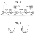
- FIG. 5 illustrates an exemplary optical system 100 formed in accordance with the present invention, where components similar to those illustrated in FIG. 1 include an additional "0" in their reference numeral.
- a first Raman source 220 1 is included in system 100 and used to provide for amplification along first optical fiber section160 1
- a second Raman source 220 2 is disposed as shown to provide for amplification along second fiber section 160 2 .
- the optical power along each separate span will be essentially “symmetric", as shown in the optical power distribution graphs included in FIG. 6. Therefore, the performance of OPC 200 will be significantly improved and, in general, can now be used for spans of any length.
- FIGs. 7 and 8 illustrate the improvement in linearity that may be achieved by including post-OPC Raman gain in accordance with the present invention.
- FIG. 7(a) illustrates the "prior art" eye diagram associated with the center channel of a 10Gb/s , 10x80km WDM network. The center channel was chosen for analysis since this region exhibits the highest level of cross-phase modulation.
- FIG. 7(b) illustrates the eye diagram associated with the same channel when a conventional mid-span OPC device is used. As shown, a relatively large amount of noise remains across the "logic 1" level of the eye diagram.
- FIG. 7(a) illustrates the "prior art" eye diagram associated with the center channel of a 10Gb/s , 10x80km WDM network. The center channel was chosen for analysis since this region exhibits the highest level of cross-phase modulation.
- FIG. 7(b) illustrates the eye diagram associated with the same channel when a conventional mid-span OPC device is used. As shown, a relatively large amount
- FIG. 7(c) in contrast, contains an eye diagram for the same central channel of the 10Gb/s system, this time incorporating Raman amplification in the fiber span following the OPC device.
- FIGs. 8(a) - (c) contain similar eye diagrams for a 40Gb/s, 10x80km WDM network. In both cases, the inclusion of Raman amplification is shown to significantly reduce the presence of both self-phase modulation and cross-phase modulation.
- Peaks A illustrated in FIG. 9 denote unchanged WDM channels as they propagate through 160km of fiber.
- the stronger peaks (1) are the desired WDM channels; weaker peaks (2) are as a result of four-wave mixing and other nonlinearities.
- peaks B are associated with a system of the present invention, clearly showing the significant reduction in four-wave mixing sidebands (i.e., the weaker peaks (2) with respect to the stronger peaks (2) of the desired WDM channels.
- Raman sources 220 are disposed so as to provide for counter-propagating gain signals for both fiber spans 160 1 and 160 2 .
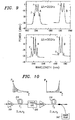
- Kerr-effect non-linearities can be compensated, in accordance with the present invention, by including a Raman pump in only the fiber span following an OPC device.
- FIG. 10 illustrates this more generalized arrangement of the present invention, as well as the associated power distribution spectrums.
- an optical signal first passes through an amplifier 300 (preferably, an EDFA), and is coupled onto a first section of optical transmission fiber 310.
- the non-linear phase accumulated with the signal traversing span 310 is illustrated by the shaded portion of the power distribution associated with span 310.
- the optical signal then passes through an OPC 320 (similar in function to those described above), and is coupled into a second section of optical transmission fiber 330.
- a Raman pump source 340 is used to couple gain signal into the output end of fiber 330.
- the power distribution associated with this second fiber span 330 is also depicted in FIG. 10, clearly showing in the shaded region the compensation - toward the end of the fiber - that will balance the nonlinearity present in the input portion of fiber section 310.
- an arrangement such as that of FIG. 10 can be repeated many times over in order to reach the total desired length for a complete transmission system.
Description
- The present invention relates to a high speed optical transmission system and, more particularly, to an optical transmission system utilizing optical phase conjugation with included Raman amplification to reduce the presence of four-wave mixing and other Kerr effect nonlinearities in the transmission fiber.
- In optical communication systems which utilize optical fiber as a transmission medium, chromatic dispersion and fiber nonlinearities present significant obstacles to achieving higher system data rates and longer repeater-less transmission distances. Chromatic dispersion, often simply referred to as "dispersion", refers to a phenomenon in which the speed of an optical signal through an optical transmission medium (such as fiber) varies as a function of the optical signal wavelength. The problem of chromatic dispersion is particularly significant in the standard single mode fiber (SMF) making up much of the world's existing optical transmission system infrastructure. Standard SMF typically exhibits a dispersion zero at a wavelength of about 1330nm, with positive dispersion for wavelengths longer than the dispersion zero.
- Dispersion can be expressed in terms of variations in the propagation constant of the fiber with respect to frequency. First- and second-order group velocity dispersion refer to the second and third derivatives of the fiber propagation constant β with respect to angular frequency ω, or β2 and β3, respectively. Higher order dispersion terms can be approximated as zero in most applications. When used in the context of lightwave transmission systems, first- and second-order dispersion are commonly expressed in terms of derivatives with respect to wavelength. Thus, first-order group velocity dispersion is typically expressed as a change in pulse propagation time over a unit length of fiber with respect to a change in pulse wavelength. In this case, the symbol D(λ) is often used to refer to first-order group velocity dispersion, and the units are typically picoseconds per nanometer-kilometer (ps/nm-km). Second-order group velocity dispersion is then expressed, using units of λps/nm2-km, as the derivative with respect to the wavelength of D(λ).
- Besides chromatic dispersion, Kerr-effect non-linearities inherent within the glass fiber can limit its transmission capabilities. In these non-linearities, the index of refraction increases with the intensity of an applied optical signal. Changes in the fiber index of refraction modulate the phase of an optical signal passing through the fiber, and thereby redistribute the signal frequency spectrum. In multi-channel systems, in which one signal causes modulation of other signals, this phenomenon manifests itself as unwanted spectral sidebands surrounding the signal wavelength. These non-linearities are usually classified as four-wave mixing (FWM), self-phase modulation (SPM) and cross-phase modulation (XPM). For long distance communication over optical fiber, dispersion and nonlinearities must be controlled, compensated, or suppressed.
- Furthermore, these nonlinearities become even worse as the optical power launched into the fiber increases. As the information carried along the optical fibers is modulated at faster and faster rates, the power being used per channel rises, with a corresponding worsening of optical nonlinearities. At the same time, fibers with low dispersion are also being widely deployed and optical systems with dense wavelength division multiplexing (DWDM) are viewed as the solution for an increasing need in information capacity. These two last factors also contribute to exacerbate the generation of the above-mentioned unwanted spectral sidebands due to FWM. Moreover, XPM and SPM penalties also increase when fiber with low dispersion is used, as well as when the channel spacing is reduced. Techniques for lowering the optical power present in these sidebands and to reduce those nonlinearities are thus highly desirable for optical telecommunication systems.
- One prior art technique for overcoming the presence of these nonlinearities is the use of mid-span optical phase conjugation. Because the phase conjugate of an optical pulse is, in effect, a time reversal of the pulse, an optical phase conjugator placed at the midpoint of an optical fiber span allows the first-order group velocity dispersion of the first half of the span to be compensated by the identical first-order group velocity dispersion produced as the conjugated signal propagates along the second half of the span. U.S. Patent 5,798,853 issued to S. Watanabe on August 25, 1998 describes one such prior art optical phase conjugation arrangement. As discussed, mid-span optical phase conjugation (OPC) can reduce the overall non-linearities in the fiber, based on the same time reversal argument, as long as the absorption in the fiber is low. Another transmission system using optical phase conjugation is known from EP-A-0 776 103.
- A remaining problem with this and other prior art solutions to the fiber nonlinearity problem is that optical phase conjugation is only applicable in situations where the fiber absorption is low. Since absorption is naturally a function of the length of the fiber, the prior art optical phase conjunction technique is best suited for short-span situations. Since the industry trend is toward longer and longer spans (and since nonlinearities are, in fact, more problematic for longer spans), a need remains for addressing the fiber nonlinearities in long-haul communication systems.
- The need remaining in the prior art is addressed by the present invention, as defined in
claim 1 which relates to an optical transmission system utilizing optical phase conjugation with included Raman amplification to reduce the presence of four-wave mixing and other Kerr effect nonlinearities in the transmission fiber. - In accordance with the teachings of the present invention, the phase conjugation compensation is improved by inserting Raman gain in each fiber span (or in another embodiment, in alternate fiber spans) so as to provide for symmetric power distribution along the length of the fiber. By providing this gain in the specified spans, four-waving mixing and other nonlinearities are significantly reduced.
- In a preferred embodiment of the present invention, each Raman amplification signal is applied as a counter-propagating signal with respect to the propagation direction of the information signal(s). Alternatively, counter-propagating Raman pumps can be used in only the fiber spans that follow the OPC device.
- It is an aspect of the present invention that the Raman amplification technique for providing symmetrical power distribution surrounding an optical phase conjugator can be used with virtually any conjugator arrangement.
- Other and further aspects of the present invention will become apparent during the course of the following discussion and by reference to the accompanying drawings.
- Referring now to the drawings,
- FIG. 1 illustrates a prior art optical transmission system, including a depiction of optical power distribution along the length of the system;
- FIG. 2 illustrates an exemplary optical phase conjugator;
- FIG. 3 is a graph illustrating the results of optical phase conjugation using the cascaded χ(2) optical phase conjugator of FIG. 2;
- FIG. 4 is a depiction of a hypothetical optical transmission system including symmetric power distribution across the length of the transmission system;
- FIG. 5 illustrates an exemplary transmission system of the present invention, incorporating Raman gain into each fiber span, where counter-propagating Raman gain is introduced to provide symmetrical power distribution;
- FIG. 6 is a graph illustrating the improvement in symmetrical power distribution by virtue of the inclusion of Raman gain in accordance with the present invention;
- FIGs. 7(a) - 7(c) contain eye diagrams associated with a 10Gb/s WDM network, illustrating the improvement in performance using Raman amplification in accordance with the present invention;
- FIGs. 8(a) - 8(c) contain eye diagrams associated with a 40Gb/s WDM network, illustrating the improvement in performance using Raman amplification in accordance with the present invention;
- FIG. 9 is a graph comparing optical output power as a function of wavelength for a prior art system to the arrangement of the present invention, illustrating in particular the sidelobe reduction possible with the present invention; and
- FIG. 10 illustrates an exemplary "Raman amplification unit" - including Raman gain in only the span following the OPC, where this unit may be repeated multiple times in order to reach the desired the length of an optical transmission system.
- A prior art
optical transmission system 10 utilizing optical phase conjugation is illustrated in FIG. 1.System 10 includes anoptical signal transmitter 12 at one end of an optical fiber transmission path made up of a number of fiber amplifiers 14 disposed between sequentialoptical fiber sections 16. The amplifiers may be, for example, erbium-doped fiber amplifiers (EDFAs), which compensate for the attenuation of the optical fiber and are spaced in a manner to approximate a lossless power distribution over the entire transmission path. Anoptical receiver 18 is located, as shown, at the opposite end of the transmission path.System 10 also includes an optical phase conjugator (OPC) 20, located at "mid-span" of the system, which produces a phase conjugate of an input signal in order to compensate for the effects of chromatic dispersion and other nonlinearities in the fiber.OPC 20 does not require accurate knowledge of the dispersion of each fiber span, as long as the mid-point is accessible and the two resulting halves produce similar accumulated dispersion. Also shown in FIG. 1 is a (simplified) graph of the optical power distribution along each half of the transmission system. - FIG. 2 illustrates an
exemplary OPC 20, defined as a cascaded second order nonlinearity (χ(2)) device formed in a highly efficient nonlinear material, such as periodically poled LiNbO3 (PPLN) waveguides. It is to be understood that this particular optical phase conjugator is exemplary only, and there exist in the art a variety of arrangements for providing optical phase conjugation. In general, an optical phase conjugator utilizes a strong pump signal at ωp that is launched simultaneously with information signals at various ωs. For this particular OPC device, both pump and signals lie in the 1.5µm band. The pump frequency is doubled to 2ωp inside the waveguide and simultaneously difference frequency mixed with the signals in order to generate wavelength-shifted outputs ωout=2ωp-ωs. The converted electric field is the complex conjugate of the input signal electric field, a feature that can be used to invert the chirp of the input signals. - Referring to FIG. 2,
OPC 20 is illustrated as including a periodically-poled LiNbO3 waveguide substrate 22 into which is coupled both a pump signal at a predetermined wavelength λP and (in this example) a plurality of information signals modulated at wavelengths λA - λD. In particular, a χ(2)-based device for 1.5µm band wavelength conversion uses a pump in the 1550nm region. The pump signal is first amplified by an erbium-doped fiber amplifier (EDFA) 24 and then filtered through a bandpassoptical filter 26 in order to suppress any amplified spontaneous emission (ASE) which may be present. This amplified and filtered pump signal is then combined with the four different optical signals and launched intoPPLN waveguide 22. FIG. 3 illustrates the output fromPPLN waveguide 22, showing both the spectrums associated with the input signals (A, B, C and D), and the phase conjugated signals (D', C', B', A') produced byPPLN waveguide 22. It is clear from the graph of FIG. 3 that the conversion efficiency for each wavelength/channel is essentially identical. Further details of the properties and workings of an optical phase conjugator can be found elsewhere in the literature and are not considered germane to the subject matter of the present invention. - As mentioned above, a problem with the prior art arrangement as shown in FIG. 1 is that optical phase conjugation is best suited for systems where the fiber absorption is low (from the point of view of removing nonlinearities), thus limiting the usefulness of OPC to relatively short fiber spans. Referring to FIG. 1, it is clear that the optical power is significantly reduced by the time the signal reaches
OPC 20. Ideally, OPC is most effective in systems which exhibit "symmetric" power distribution, as shown in FIG. 4. Clearly, this is a hypothetical situation, since fiber absorption will always result in a decrease in power. - The arrangement of the present invention overcomes this limitation by inserting Raman gain in each fiber span so as to provide for "symmetric" power distribution in both halves of the transmission system. FIG. 5 illustrates an exemplary
optical system 100 formed in accordance with the present invention, where components similar to those illustrated in FIG. 1 include an additional "0" in their reference numeral. In accordance with the present invention, afirst Raman source 2201 is included insystem 100 and used to provide for amplification along first optical fiber section1601, and asecond Raman source 2202 is disposed as shown to provide for amplification along second fiber section 1602. As a result of the Raman amplification, the optical power along each separate span will be essentially "symmetric", as shown in the optical power distribution graphs included in FIG. 6. Therefore, the performance ofOPC 200 will be significantly improved and, in general, can now be used for spans of any length. - FIGs. 7 and 8 illustrate the improvement in linearity that may be achieved by including post-OPC Raman gain in accordance with the present invention. In particular, FIG. 7(a) illustrates the "prior art" eye diagram associated with the center channel of a 10Gb/s , 10x80km WDM network. The center channel was chosen for analysis since this region exhibits the highest level of cross-phase modulation. FIG. 7(b) illustrates the eye diagram associated with the same channel when a conventional mid-span OPC device is used. As shown, a relatively large amount of noise remains across the "
logic 1" level of the eye diagram. FIG. 7(c), in contrast, contains an eye diagram for the same central channel of the 10Gb/s system, this time incorporating Raman amplification in the fiber span following the OPC device. FIGs. 8(a) - (c) contain similar eye diagrams for a 40Gb/s, 10x80km WDM network. In both cases, the inclusion of Raman amplification is shown to significantly reduce the presence of both self-phase modulation and cross-phase modulation. - The results achieved with the implementation of the present invention are illustrated in the graph of FIG. 9. Peaks A illustrated in FIG. 9 denote unchanged WDM channels as they propagate through 160km of fiber. The stronger peaks (1) are the desired WDM channels; weaker peaks (2) are as a result of four-wave mixing and other nonlinearities. In contrast, peaks B are associated with a system of the present invention, clearly showing the significant reduction in four-wave mixing sidebands (i.e., the weaker peaks (2) with respect to the stronger peaks (2) of the desired WDM channels.
- In the arrangement of the present invention as shown in FIG. 5,
Raman sources 220 are disposed so as to provide for counter-propagating gain signals for both fiber spans 1601 and 1602. In its most general form, however, Kerr-effect non-linearities can be compensated, in accordance with the present invention, by including a Raman pump in only the fiber span following an OPC device. FIG. 10 illustrates this more generalized arrangement of the present invention, as well as the associated power distribution spectrums. As shown, an optical signal first passes through an amplifier 300 (preferably, an EDFA), and is coupled onto a first section ofoptical transmission fiber 310. The non-linear phase accumulated with thesignal traversing span 310 is illustrated by the shaded portion of the power distribution associated withspan 310. The optical signal then passes through an OPC 320 (similar in function to those described above), and is coupled into a second section ofoptical transmission fiber 330. ARaman pump source 340 is used to couple gain signal into the output end offiber 330. The power distribution associated with thissecond fiber span 330 is also depicted in FIG. 10, clearly showing in the shaded region the compensation - toward the end of the fiber - that will balance the nonlinearity present in the input portion offiber section 310. In general, an arrangement such as that of FIG. 10 can be repeated many times over in order to reach the total desired length for a complete transmission system. - It is to be understood that these and other arrangements of the present invention are useful with any type of optical phase conjugation arrangement, the particular embodiment as shown in FIG. 2 is to be considered as exemplary only. In general, the subject matter of the present invention is considered to be limited only by the scope of the claims appended hereto:
Claims (8)
- An optical transmission system comprising
an input optical fiber transmission span (1601) for receiving an input signal exhibiting an original phase from an optical transmitter (120) and providing for propagation of said received input signal, said input optical fiber having a known optical power absorption;
an optical phase conjugator (200) disposed at the endpoint of the input optical fiber transmission span for converting the original phase of the input signal to essentially remove nonlinearities attributed to transmission along the input optical fiber transmission span by forming a phase conjugated optical signal;
an output optical fiber transmission span (1602) coupled to the optical phase conjugator for receiving the phase conjugated optical signal and providing for propagation of said phase conjugated optical signal toward an optical receiver, said output optical fiber having a known optical power absorption;
an optical amplifier (1402) is disposed along the output optical fiber transmission span; characterised in that in addition to the optical amplifier
a Raman gain element (2202) is disposed to inject a counter-propagating gain signal into the output optical fiber span to provide for essentially symmetric optical power distribution between said input optical fiber and said output optical fiber. - The optical transmission system as defined in claim 1 wherein the optical phase conjugator is disposed at essentially the mid-point of said system such that the length of the input optical fiber is essentially equal to the length of the output optical fiber.
- The optical transmission system as defined in claim 1 wherein the system further comprises a second Raman gain element (2201) disposed to inject a counter-propagating gain signal into the input optical fiber.
- The optical transmission system as defined in claim 1 wherein the optical phase conjugator is a cascaded .χ.(2) wavelength converter.
- The optical transmission system as defined in claim 1 wherein a second optical amplifier (1401) is disposed along the input optical fiber transmission span.
- The optical transmission system as defined in claim 5 wherein the second optical amplifier comprises an erbium-doped fiber amplifier.
- The optical transmission system as defined in claim 1 wherein the optical amplifier comprises an erbium-doped fiber amplifier.
- The optical transmission system as defined in claim 5 wherein the first and second optical amplifiers comprise erbium-doped fiber amplifiers.
Applications Claiming Priority (2)
| Application Number | Priority Date | Filing Date | Title |
|---|---|---|---|
| US519654 | 2000-03-06 | ||
| US09/519,654 US6704519B1 (en) | 2000-03-06 | 2000-03-06 | Optical transmission system with reduced Kerr effect nonlinearities |
Publications (3)
| Publication Number | Publication Date |
|---|---|
| EP1133031A2 EP1133031A2 (en) | 2001-09-12 |
| EP1133031A3 EP1133031A3 (en) | 2005-01-05 |
| EP1133031B1 true EP1133031B1 (en) | 2007-05-09 |
Family
ID=24069225
Family Applications (1)
| Application Number | Title | Priority Date | Filing Date |
|---|---|---|---|
| EP01301719A Expired - Lifetime EP1133031B1 (en) | 2000-03-06 | 2001-02-26 | Optical transmission system with reduced kerr effect nonlinearities |
Country Status (5)
| Country | Link |
|---|---|
| US (1) | US6704519B1 (en) |
| EP (1) | EP1133031B1 (en) |
| JP (1) | JP4309071B2 (en) |
| CA (1) | CA2332696C (en) |
| DE (1) | DE60128281T2 (en) |
Families Citing this family (15)
| Publication number | Priority date | Publication date | Assignee | Title |
|---|---|---|---|---|
| US20050018984A1 (en) * | 2001-09-28 | 2005-01-27 | Fabrizio Carbone | Optical transmission system comprising dispersion management system |
| US20030118347A1 (en) * | 2001-12-21 | 2003-06-26 | Spectralane | Spectral inversion and chromatic dispersion management in optical transmission systems |
| DE60208669T2 (en) | 2002-03-22 | 2006-09-28 | Pirelli & C. S.P.A. | OPTICAL TRANSMISSION SYSTEM WITH OPTICAL PHASE CONJUGATOR DEVICE |
| ATE362241T1 (en) * | 2002-03-22 | 2007-06-15 | Pirelli & C Spa | OPTICAL TRANSMISSION SYSTEM COMPRISING AN OPTICAL PHASE CONJUGATION DEVICE |
| US7310318B1 (en) | 2002-05-03 | 2007-12-18 | Ciena Corporation | Method and system for using optical phase conjugation in an optical communications network |
| US7016583B2 (en) | 2003-01-31 | 2006-03-21 | Corning Incorporated | Dispersion management with phase conjugation |
| US20040234275A1 (en) * | 2003-05-20 | 2004-11-25 | Aref Chowdhury | Process for optical communication and system for same |
| US7558485B2 (en) * | 2003-05-20 | 2009-07-07 | Alcatel-Lucent Usa Inc. | Processes and systems involving optical phase conjugators |
| US7454144B2 (en) * | 2003-12-05 | 2008-11-18 | Lucent Technologies Inc. | Low total excursion dispersion maps |
| KR100613905B1 (en) * | 2004-11-04 | 2006-08-21 | 한국전자통신연구원 | Apparatus and Method for Compensating Distortion of Optical Signal |
| CN100347602C (en) * | 2005-01-21 | 2007-11-07 | 清华大学 | Method for improving output power, qualities of spectrum and light beam in laser of optical fiber |
| US9054807B2 (en) * | 2005-05-26 | 2015-06-09 | Alcatel Lucent | Reducing crosstalk in optical wavelength converters |
| US8280258B2 (en) * | 2009-06-30 | 2012-10-02 | Ciena Corporation | Optical communication systems and methods utilizing a split amplification band and nonlinear compensation |
| US9088365B2 (en) * | 2012-10-04 | 2015-07-21 | Nec Laboratories America, Inc. | Optical phase conjugation aided long-haul transmission system with enhanced signal-to-noise ratio and nonlinear tolerance |
| JP2016071063A (en) * | 2014-09-29 | 2016-05-09 | 沖電気工業株式会社 | Phase conjugate light generation element and phase conjugate light generation device |
Family Cites Families (11)
| Publication number | Priority date | Publication date | Assignee | Title |
|---|---|---|---|---|
| US4769820A (en) * | 1987-10-16 | 1988-09-06 | Avco Research Laboratory, Inc. | Means for and method of improving transmission of a data carrying laser beam |
| US5058974A (en) * | 1989-10-06 | 1991-10-22 | At&T Bell Laboratories | Distributed amplification for lightwave transmission system |
| JP3419510B2 (en) | 1992-10-16 | 2003-06-23 | 富士通株式会社 | Optical communication system with chromatic dispersion compensation and phase conjugate light generator applicable to the system |
| US5596667A (en) | 1992-10-20 | 1997-01-21 | Fujitsu Limited | Application of phase conjugate optics to optical systems |
| US5365362A (en) * | 1993-09-10 | 1994-11-15 | At&T Bell Laboratories | Ultra-high capacity non-soliton optical transmission using optical phase conjugation |
| JPH0822038A (en) * | 1994-07-08 | 1996-01-23 | Sumitomo Electric Ind Ltd | Phase conjugated light generator |
| US5532868A (en) | 1994-09-23 | 1996-07-02 | At&T Corp. | Apparatus and method for compensating chromatic dispersion produced in optical phase conjugation or other types of optical signal conversion |
| US6160942A (en) * | 1994-10-20 | 2000-12-12 | Fujitsu Limited | Optical fiber communication system using optical phase conjugation |
| JP3506283B2 (en) | 1995-03-20 | 2004-03-15 | 富士通株式会社 | Optical phase conjugator |
| US6175435B1 (en) * | 1995-11-22 | 2001-01-16 | Fujitsu Limited | Optical communication system using optical phase conjugation to suppress waveform distortion caused by chromatic dispersion and optical kerr effect |
| US5920588A (en) | 1996-04-11 | 1999-07-06 | Fujitsu Limited | Method and device for generation of phase conjugate light and wavelength conversion, and system having the device |
-
2000
- 2000-03-06 US US09/519,654 patent/US6704519B1/en not_active Expired - Fee Related
-
2001
- 2001-01-26 CA CA002332696A patent/CA2332696C/en not_active Expired - Fee Related
- 2001-02-26 EP EP01301719A patent/EP1133031B1/en not_active Expired - Lifetime
- 2001-02-26 DE DE60128281T patent/DE60128281T2/en not_active Expired - Lifetime
- 2001-03-02 JP JP2001058123A patent/JP4309071B2/en not_active Expired - Fee Related
Also Published As
| Publication number | Publication date |
|---|---|
| CA2332696C (en) | 2005-05-03 |
| US6704519B1 (en) | 2004-03-09 |
| DE60128281D1 (en) | 2007-06-21 |
| DE60128281T2 (en) | 2008-01-10 |
| EP1133031A2 (en) | 2001-09-12 |
| JP4309071B2 (en) | 2009-08-05 |
| CA2332696A1 (en) | 2001-09-06 |
| EP1133031A3 (en) | 2005-01-05 |
| JP2001285198A (en) | 2001-10-12 |
Similar Documents
| Publication | Publication Date | Title |
|---|---|---|
| EP0703680B1 (en) | Apparatus and method for compensating chromatic dispersion produced in optical phase conjugation or other types of optical signal conversion | |
| EP1130456B1 (en) | Method, device, and system for waveform shaping of signal light | |
| Watanabe et al. | Simultaneous wavelength conversion and optical phase conjugation of 200 Gb/s (5/spl times/40 Gb/s) WDM signal using a highly nonlinear fiber four-wave mixer | |
| EP1133031B1 (en) | Optical transmission system with reduced kerr effect nonlinearities | |
| US7027468B2 (en) | Phase-insensitive recovery of clock pulses of wavelength division multiplexed optical signals | |
| EP0987583A2 (en) | Polarisation-independent phase-conjugation apparatus and system comprising this apparatus | |
| Feiste et al. | 40 Gbit/s transmission over 434 km standard-fiber using polarisation independent mid-span spectral inversion | |
| US7187868B2 (en) | Wavelength division multiplexing optical transmission system using a spectral inversion device | |
| Ghosh et al. | Suppression of four-wave mixing in a 22× 10 Gbps dense wavelength division multiplexed system by linearly chirped fiber Bragg gratings | |
| Brener et al. | Cancellation of all Kerr nonlinearities in long fiber spans using a LiNbO 3 phase conjugator and Raman amplification | |
| Belardi et al. | A 10GBIT/S Tuneable Wavelength Converter Based on Four-Wave MIXING in Highly Nonlinear Holey Fibre | |
| Brener et al. | Cancellation of all Kerr nonlinearities in long fiber spans using a LiNbO/sub 3/phase conjugator and Raman amplification | |
| Mustafa et al. | Dispersion compensation in silica doped fiber using soliton transmission technique over cascaded FBG | |
| JP2017085572A (en) | Erasure of wavelength shift in spectrum inversion in optical network | |
| US6496615B2 (en) | WDM transmission system | |
| US7319823B2 (en) | Modulation scheme and transmission system for NRZ signals with left and right side filtering | |
| Rasheed et al. | Novel approaches for suppression of four wave mixing in wdm system using concocted modulation techniques | |
| KR100533600B1 (en) | Wavelength division multiplexed metro optical communication apparatus | |
| Song et al. | Experimental study of four wave mixing in non-zero dispersion fiber | |
| US7493050B2 (en) | Optical communication system having an antiresonant dispersion map suppressing four wave mixing and cross phase modulation | |
| Tur et al. | Modules for chromatic dispersion and dispersion slope management | |
| Cai et al. | Dynamic dispersion compensation in a 10-Gbit/s optical systems using a novel nonlinearly chirped fiber Bragg grating | |
| Artiglia | Upgrading installed systems to multigigabit bit-rates by means of dispersion compensation | |
| Murakami et al. | FWM generation in higher order fiber dispersion managed transmission line | |
| EP1282247B1 (en) | Wavelength division multiplexing optical transmission system using a spectral inversion device |
Legal Events
| Date | Code | Title | Description |
|---|---|---|---|
| PUAI | Public reference made under article 153(3) epc to a published international application that has entered the european phase |
Free format text: ORIGINAL CODE: 0009012 |
|
| AK | Designated contracting states |
Kind code of ref document: A2 Designated state(s): AT BE CH CY DE DK ES FI FR GB GR IE IT LI LU MC NL PT SE TR |
|
| AX | Request for extension of the european patent |
Free format text: AL;LT;LV;MK;RO;SI |
|
| PUAL | Search report despatched |
Free format text: ORIGINAL CODE: 0009013 |
|
| RIC1 | Information provided on ipc code assigned before grant |
Ipc: 7H 01S 3/30 A Ipc: 7H 04B 10/18 B |
|
| AK | Designated contracting states |
Kind code of ref document: A3 Designated state(s): AT BE CH CY DE DK ES FI FR GB GR IE IT LI LU MC NL PT SE TR |
|
| AX | Request for extension of the european patent |
Extension state: AL LT LV MK RO SI |
|
| 17P | Request for examination filed |
Effective date: 20050625 |
|
| AKX | Designation fees paid |
Designated state(s): DE FR GB IT |
|
| APBN | Date of receipt of notice of appeal recorded |
Free format text: ORIGINAL CODE: EPIDOSNNOA2E |
|
| APBR | Date of receipt of statement of grounds of appeal recorded |
Free format text: ORIGINAL CODE: EPIDOSNNOA3E |
|
| APBV | Interlocutory revision of appeal recorded |
Free format text: ORIGINAL CODE: EPIDOSNIRAPE |
|
| GRAP | Despatch of communication of intention to grant a patent |
Free format text: ORIGINAL CODE: EPIDOSNIGR1 |
|
| GRAS | Grant fee paid |
Free format text: ORIGINAL CODE: EPIDOSNIGR3 |
|
| GRAA | (expected) grant |
Free format text: ORIGINAL CODE: 0009210 |
|
| AK | Designated contracting states |
Kind code of ref document: B1 Designated state(s): DE FR GB IT |
|
| REG | Reference to a national code |
Ref country code: GB Ref legal event code: FG4D |
|
| REF | Corresponds to: |
Ref document number: 60128281 Country of ref document: DE Date of ref document: 20070621 Kind code of ref document: P |
|
| ET | Fr: translation filed | ||
| PLBE | No opposition filed within time limit |
Free format text: ORIGINAL CODE: 0009261 |
|
| STAA | Information on the status of an ep patent application or granted ep patent |
Free format text: STATUS: NO OPPOSITION FILED WITHIN TIME LIMIT |
|
| 26N | No opposition filed |
Effective date: 20080212 |
|
| REG | Reference to a national code |
Ref country code: GB Ref legal event code: 732E Free format text: REGISTERED BETWEEN 20131107 AND 20131113 |
|
| REG | Reference to a national code |
Ref country code: FR Ref legal event code: CD Owner name: ALCATEL-LUCENT USA INC. Effective date: 20131122 |
|
| REG | Reference to a national code |
Ref country code: FR Ref legal event code: GC Effective date: 20140410 |
|
| REG | Reference to a national code |
Ref country code: FR Ref legal event code: RG Effective date: 20141015 |
|
| REG | Reference to a national code |
Ref country code: FR Ref legal event code: PLFP Year of fee payment: 15 |
|
| PGFP | Annual fee paid to national office [announced via postgrant information from national office to epo] |
Ref country code: IT Payment date: 20150219 Year of fee payment: 15 Ref country code: DE Payment date: 20150219 Year of fee payment: 15 |
|
| PGFP | Annual fee paid to national office [announced via postgrant information from national office to epo] |
Ref country code: GB Payment date: 20150218 Year of fee payment: 15 Ref country code: FR Payment date: 20150219 Year of fee payment: 15 |
|
| REG | Reference to a national code |
Ref country code: DE Ref legal event code: R119 Ref document number: 60128281 Country of ref document: DE |
|
| GBPC | Gb: european patent ceased through non-payment of renewal fee |
Effective date: 20160226 |
|
| REG | Reference to a national code |
Ref country code: FR Ref legal event code: ST Effective date: 20161028 |
|
| PG25 | Lapsed in a contracting state [announced via postgrant information from national office to epo] |
Ref country code: IT Free format text: LAPSE BECAUSE OF NON-PAYMENT OF DUE FEES Effective date: 20160226 |
|
| PG25 | Lapsed in a contracting state [announced via postgrant information from national office to epo] |
Ref country code: DE Free format text: LAPSE BECAUSE OF NON-PAYMENT OF DUE FEES Effective date: 20160901 Ref country code: GB Free format text: LAPSE BECAUSE OF NON-PAYMENT OF DUE FEES Effective date: 20160226 Ref country code: FR Free format text: LAPSE BECAUSE OF NON-PAYMENT OF DUE FEES Effective date: 20160229 |