EP1132789A2 - Machining control system - Google Patents
Machining control system Download PDFInfo
- Publication number
- EP1132789A2 EP1132789A2 EP01105381A EP01105381A EP1132789A2 EP 1132789 A2 EP1132789 A2 EP 1132789A2 EP 01105381 A EP01105381 A EP 01105381A EP 01105381 A EP01105381 A EP 01105381A EP 1132789 A2 EP1132789 A2 EP 1132789A2
- Authority
- EP
- European Patent Office
- Prior art keywords
- machining
- adaptive control
- tool
- conditions
- tools
- Prior art date
- Legal status (The legal status is an assumption and is not a legal conclusion. Google has not performed a legal analysis and makes no representation as to the accuracy of the status listed.)
- Granted
Links
Images


Classifications
-
- G—PHYSICS
- G05—CONTROLLING; REGULATING
- G05B—CONTROL OR REGULATING SYSTEMS IN GENERAL; FUNCTIONAL ELEMENTS OF SUCH SYSTEMS; MONITORING OR TESTING ARRANGEMENTS FOR SUCH SYSTEMS OR ELEMENTS
- G05B19/00—Program-control systems
- G05B19/02—Program-control systems electric
- G05B19/18—Numerical control [NC], i.e. automatically operating machines, in particular machine tools, e.g. in a manufacturing environment, so as to execute positioning, movement or co-ordinated operations by means of program data in numerical form
- G05B19/416—Numerical control [NC], i.e. automatically operating machines, in particular machine tools, e.g. in a manufacturing environment, so as to execute positioning, movement or co-ordinated operations by means of program data in numerical form characterised by control of velocity, acceleration or deceleration
- G05B19/4163—Adaptive control of feed or cutting velocity
-
- G—PHYSICS
- G05—CONTROLLING; REGULATING
- G05B—CONTROL OR REGULATING SYSTEMS IN GENERAL; FUNCTIONAL ELEMENTS OF SUCH SYSTEMS; MONITORING OR TESTING ARRANGEMENTS FOR SUCH SYSTEMS OR ELEMENTS
- G05B2219/00—Program-control systems
- G05B2219/30—Nc systems
- G05B2219/49—Nc machine tool, till multiple
- G05B2219/49061—Calculate optimum operating, machining conditions and adjust, adapt them
-
- G—PHYSICS
- G05—CONTROLLING; REGULATING
- G05B—CONTROL OR REGULATING SYSTEMS IN GENERAL; FUNCTIONAL ELEMENTS OF SUCH SYSTEMS; MONITORING OR TESTING ARRANGEMENTS FOR SUCH SYSTEMS OR ELEMENTS
- G05B2219/00—Program-control systems
- G05B2219/30—Nc systems
- G05B2219/49—Nc machine tool, till multiple
- G05B2219/49069—Adaptive control optimalisation ACO
-
- Y—GENERAL TAGGING OF NEW TECHNOLOGICAL DEVELOPMENTS; GENERAL TAGGING OF CROSS-SECTIONAL TECHNOLOGIES SPANNING OVER SEVERAL SECTIONS OF THE IPC; TECHNICAL SUBJECTS COVERED BY FORMER USPC CROSS-REFERENCE ART COLLECTIONS [XRACs] AND DIGESTS
- Y10—TECHNICAL SUBJECTS COVERED BY FORMER USPC
- Y10T—TECHNICAL SUBJECTS COVERED BY FORMER US CLASSIFICATION
- Y10T483/00—Tool changing
- Y10T483/12—Tool changing with means to regulate operation by means of replaceable information supply [e.g., templet, tape, card, etc. ]
Definitions
- This invention relates to a machining control system for controlling machining state(s) of machine tools and, more particularly, to a machining control system made up of numerical controllers (NCs) which has functions of automatically determining machining conditions or automatic programming systems , or machining control systems made up of the combination of programming devices such as CAMs with numerical controllers.
- NCs numerical controllers
- Another approach is directed to an adaptive control system disclosed in Japanese Patent Laid-Open No. 62-292347 (refer to Fig. 14), Japanese Patent Laid-Open No. 2-218538, Japanese Patent Laid-Open No. 6-8106, and the like.
- the machining states are monitored on the basis of signals obtained by sensors or the like and the machining conditions are changed in such a manner that an objective function is optimized while keeping given constraints, to thereby control the machining in an appropriate state.
- This approach changes the machining conditions at a real time in accordance with the actual machining states, and is mainly applied to the numerical controller or the like. In the following description, the approach of this type is called "second approach".
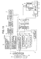
- Fig. 13 is a block diagram showing the structure of conventional system using the first approach (disclosed in Japanese Patent Publication No. 7-41516) among the above conventional approaches.
- reference numerals 5 and 11 denote a spindle motor and a grinding motor which are to be controlled, respectively.
- Reference numeral 14 denotes a first RAM in which data related to the shape and material of the spindle (workpiece), etc., and data related to the tool and the machining method are stored.
- Reference numeral 15 denotes a second RAM for storing standard machining data which are set therein
- 16 is an automatic machining condition setting circuit for automatically setting the machining condition on the basis of the data stored in the first and second RAMs
- 18 is a CRT for displaying the machining condition which is automatically set
- 12 is a keyboard used in the case where an operator judges that the machining condition displayed on the CRT 18 is improper and corrects the machining condition.
- a portion "a" surrounded by a phantom line is means for storing a corrected rate as the coefficient every time when the operator corrects the machining condition and automatically correcting the machining condition by using the data in the next machining.
- the machining condition setting circuit 16 the machining condition is automatically determined on the basis of the data retained in the first and second RAMs, and if a correction is necessary, the operator conducts the correction. In addition, when the correction has been conducted, the rate of the correction is retained as the coefficient, and the coefficient is used to conduct the automatic correction in the next machining.
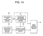
- Fig. 14 is a block diagram showing the structure of a conventional system using the second approach (disclosed in Japanese Patent Laid-Open No. 62-292347) among the above conventional approaches.
- reference numeral 40 denotes machining load detecting means for detecting a machining load
- 41 is standard machining load deriving means for sampling an output of the machining load detecting means 40 at the time of a model machining using a reference tool to derive the standard machining load on the basis of the sampled output
- 42 is machining condition setting means for setting the machining condition at the time of actual machining using a tool similar to the reference tool.
- Reference numeral 43 denotes target load calculating means for calculating a target load on the basis of the standard machining load derived by the standard machining load deriving means 41 and the machining condition at the time of actual machining which is set by the machining condition setting means 42, and 44 is feed rate control means for increasing or decreasing a feed rate such that the machining load detected by the machining load detecting means 40 at the time of actual machining becomes the target load calculated by the target load calculating means 43.
- the model machining is conducted on only the reference tool, and the machining load at the time of the model machining is detected by the machining load detecting means 40, and the standard machining load deriving means 41 derives the standard machining load on the basis of the machining load thus detected.
- the target load calculating means 43 is actuated and calculates the target load on the basis of the machining condition at the time of actual machining which is set by the machining condition setting means 42 and the reference machining load derived at the time of model machining.
- the feed rate control means 44 compares the target load thus calculated with the actual machining load detected by the machining load detecting means 40 to change the feed rate such that the detected actual load approaches the calculated target load.
- the conventional first approach is made provided that rules or models which determines the machining condition on the basis of the factors that basically influence the machining is identical with the actual machining environment and a fluctuation of the actual machining environment is sufficiently small.
- the above provision is hardly satisfied for the following reasons.
- the sufficiently safe machining condition in order to prevent the abnormality from occurring even if the unexpected phenomena occur, the sufficiently safe machining condition must be set, to thereby increase the loss, as a result of which the efficiency is lowered.
- the conventional second approach may be insufficient from the viewpoint of the efficiency and the reliability although it can cope with the variation of the machining environment to some degree. That is, because a delay of detection and control always exists in the adaptive control, there is the possibility that it takes long time to reach the optimum state or that the abnormality may occur until reaching the optimum state, depending on the initial machining condition. In particular, this leads to problems in the high speed machining which has been diffusing in recent years. For example, in a drilling process using a drill, there is a case where it does not take 0.1 seconds to drill one hole, which is not sufficiently long as compared with a normal delay (several tens msec.) of control in the adaptive control.
- the above problems are caused by the separation of the determination of the machining conditions at the machining information determination stage from the adjustment of the machining conditions at the adaptive control stage. That is, the problems reside in that the former does not take the actual machining environment and the adaptive control manner into consideration, and the latter only faithfully keeps to the given condition (the machining conditions and the control parameters).
- the present invention has been made in order to solve the above problem, and therefore an object of the present invention is to provide a machining control system which balancedly combines the determination of the machining conditions at a machining information determination stage with the adjustment of the machining conditions at an adaptive control stage, thereby being capable of keeping the optimum machining state and enhancing the efficiency and the reliability even in the case where an actual machining environment fluctuates.
- the machining control system of the present invention comprises a machining data base for storing information necessary for determining initial machining conditions, machining information determining means for obtaining the initial machining conditions on the basis of the information stored in the machining data base and in accordance with adaptive control characteristics defined by adaptive control modes and adaptive control parameters and adaptive control means for controlling the machining in appropriate states by changing the machining conditions in accordance with the machining states observed during the machining with the initial machining condition as initial value of the machining conditions.
- the machining data base may store therein information on tool characteristics, workpiece characteristics, relational expression of the machining states to the tool characteristics/the workpiece characteristics and the machining conditions, standard machining conditions and machining state target values.
- the machining information determining means may select the adaptive control characteristics such that any one of a machining period of time, a shape error, an abnormality occurrence rate and a tool wear amount becomes minimum among the plurality of adaptive control characteristics, and determines the initial machining conditions suitable for the adaptive control characteristics selected.
- the adaptive control means may analyze at least one of the tool characteristics and the workpiece characteristics on the basis of the machining states that are observed through the machining and the machining condition, and updates at least one of the informations of the tool characteristics and the workpiece characteristics which are retained in the machining data base.
- the machining data base may be structured by characteristics inherent to the tools and the workpieces now used, characteristics common to the tools and the workpieces of the same lots as those of the tools and the workpieces now used, and characteristics common to all of the tools and the workpieces of the same kinds of the tool and the workpiece now used.
- the machining information determining means may obtain the machining conditions such that the expected machining states do not exceed machining state target values taking the characteristics common to the tools of the same lot or the same kind and variations in the characteristics of the tools into consideration which are stored in the machining data base, and the machining conditions are determined as the initial machining condition.
- the machining information determining means may obtain the machining conditions such that the expected machining states do not exceed machining state target values taking the characteristics common to the workpieces of the same lot or the same kind and a variation in the characteristics of the workpieces into consideration which are stored in the machining data base, and the machining conditions are determined as the initial machining condition.
- the adaptive control means may judge that the abnormality occurs if the tool characteristics and the workpiece characteristics which are referred to in determination of the machining conditions in the machining information determining means are largely different from the tool characteristics and the workpiece characteristics which are analyzed in the adaptive control means, respectively, and updates at least one of the information of the tool characteristics and the workpiece characteristics with respect to the machining data base, and the machining information determining means re-determines the adaptive control characteristics and the machining conditions to prevent the abnormality.
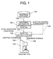
- Fig. 1 is a block diagram showing the structure of a machining control system in accordance with a first embodiment of the present invention
- Fig. 2 is a diagram showing an example of a machining data base in the machining control system in accordance with the first embodiment of the present invention
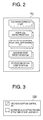
- Fig. 3 is a diagram showing an example of the adaptive control characteristics in the machining control system in accordance with the first embodiment of the present invention
- Fig. 4 is a flowchart showing the determining operation of initial machining conditions by a machining information determination portion in the machining control system in accordance with the first embodiment of the present invention
- Fig. 5 is a block diagram showing the structure of a machining control system in accordance with a second embodiment of the present invention.
- Fig. 6 is a diagram showing an example in which there are a plurality of selectable adaptive control characteristics in the machining control system in accordance with the second embodiment of the present invention.
- Fig. 7 is a flowchart showing the operation of selecting the optimum candidate from the plurality of selectable adaptive control characteristics by a machining information determination portion in the machining control system in accordance with the second embodiment of the present invention
- Fig. 8 is a graph showing the result of a process that estimates a machining period of time taking the estimated state of load into consideration in order to select the optimum candidate by the machining information determination portion in the machining control system in accordance with the second embodiment of the present invention
- Fig. 9 is a block diagram showing the structure of a machining control system in accordance with a third embodiment of the present invention.
- Fig. 10 is a diagram showing an example of the data base structured in a machining control system in accordance with a fourth embodiment of the present invention.
- Fig. 11 is a block diagram showing the structure of a machining control system in accordance with a fifth embodiment of the present invention.
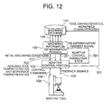
- Fig. 12 is a block diagram showing the structure of a machining control system in accordance with a seventh embodiment of the present invention.
- Fig. 13 is a diagram showing the structure of a conventional machining condition determining system.
- Fig. 14 is a diagram showing the structure of a conventional adaptive control system.
- Fig. 1 is a block diagram showing the structure of a machining control system in accordance with a first embodiment of the present invention.
- reference numeral 101 denotes a machining data base in which various information required to determine the machining conditions is stored
- 102 is a machining information determination portion (machining information determining means) for determining an initial machining condition on the basis of the information stored in the machining data base 101 and adaptive control characteristics set in an adaptive control portion 103
- 103 is the adaptive control portion (adaptive control means) for controlling the machining in an appropriate state by setting the initial machining conditions determined by the machining information determination portion 102 to initial values of the machining condition and by changing the machining conditions in accordance with machining states observed during the machining
- 104 is a machine tool to be controlled.
- reference numeral 105 denotes information on tool characteristics, workpiece characteristics, relational expressions of the machining states with respect to the tool characteristics / the workpiece characteristics and the machining conditions, standard machining conditions and machining state target values, which are stored in the machining data base 101, 106 is adaptive control characteristics outputted from the adaptive control portion 103 to the machining information determination portion 102, 107 is initial machining conditions determined by the machining information determination portion 102, 108 is control commands outputted from the adaptive control portion 103, and 109 is feedback signals outputted from the machine tool 104.
- the machining information determination portion 102 determines the initial machining conditions 107 in accordance with the information 105 on the tool characteristics, the workpiece characteristics, the relational expressions of the machining states with respect to the tool characteristics/the workpiece characteristics and the machining conditions, the standard machining conditions and the machining state target values which are acquired from the machining data base 101 and the adaptive control characteristics 106 acquired from the adaptive control portion 103.
- the machining condition is directed to a feed rate, a spindle rotation speed, a feed pattern (in the drilling process, a drill cycle during which a drill is fed to a hole bottom once, a pecking cycle during which the drill is fed to the hole bottom through several reciprocation, or the like), or parameters for adaptive control (the machining state target values or the like).
- the adaptive control portion 103 uses the initial machining conditions 107 as the machining conditions initially (or in the initial state), and thereafter (during the machining), recognizes the machining states on the basis of control commands 108 which are transmitted to the machine tool 104, feedback signals 109 such as loads which are obtained from the machine tool 104 or signals from other sensors (not shown), or the like, and transmits the control commands 108 for retaining the machining in an appropriate states to the machine tool 104 by changing the machining conditions in accordance with the machining states.
- the recognition of the machining states is made by using the known technique disclosed in, for example, Japanese Patent Laid-Open No. 9-6432.
- Fig. 2 shows an example of the machining data base 101.
- machining characteristics df, dd, K
- workpiece characteristics H
- relational expressions G()
- the tool characteristics are stored for each of the tools
- the workpiece characteristics are stored for each of the workpieces
- other information is stored for each of the combinations of the tool with the workpiece.
- the relational expression G is represented as follows, for example, in case of the torque in the tool rotating direction during the drilling process.
- G(H,K,f,df,D,dd) H ⁇ K(f ⁇ df+D ⁇ dd)
- f is a feed per revolution
- D is a diameter of the drill
- H is a hardness of the workpiece.
- mark ( ⁇ ) is adaptive such that x ⁇ y represents x y .
- K, df and dd simply denote coefficients, respectively, and specifically, K is a coefficient indicative of the cutting property of the tool, df is a coefficient indicative of the relation between the feed f and the load, and dd is a coefficient indicative of the relation between the tool diameter d and the load.
- Fig. 3 shows an example of the adaptive control characteristics 106.
- the adaptive control characteristics 106 indicate whether the adaptive control are conducted, or how the processing are additionally conducted, or not.
- the adaptive control characteristics 106 are defined by adaptive control modes and adaptive control parameters.
- the adaptive control characteristics 106 are inputted to the adaptive control portion 103 by an operator in advance before the machining control system is activated.
- Fig. 4 is a flowchart showing an example of a method of determining the initial machining conditions 107 (in this example, the feed rate, the load target value as the machining state target value and the feed pattern) in the machining information determination portion 102 in case of the drilling process.
- the load is used as the machining state.
- a standard feed rate F 0 and a spindle rotation speed S 0 are set as the feed rate and spindle rotation speed respectively. Both of F 0 and S 0 are acquired from the machining data base 101.
- the feed rate F 0 may be obtained by using the load target value Topt acquired from the machining data base 101 as the following expressions (2) and (3).
- F 0 f x S 0
- F (Topt/(H ⁇ K)-D ⁇ dd) ⁇ (1/df)
- a step ST102 it is checked whether the feed rate adaptive control is on, or not, which is the adaptive control characteristic 106, and if it is true (on), the load is maintained to the load target value by adjusting the feed rate by the adaptive control portion 103 even in the situation where the load may be unexpectedly large. Therefore, the feed rate determined in the step ST101 is adopted as it is as the initial machining condition related to the feed rate, and further in a step ST104, the load target value Topt to be maintained is acquired from the machining data base 101 and set.
- the adaptive control portion 103 decreases the feed rate to be lower than the feed rate determined in the step ST101, taking a given safety factor into consideration, and sets the feed rate thus decreased as the initial machining condition related to the feed rate.
- a step ST105 it is checked in a step ST105 whether it is a deep hole, or not.
- the check of whether it is a deep hole or not is conducted by checking whether the ratio of the depth of the hole to be machined to the diameter thereof exceeds a given value (for example, about 3), or not.
- a given value for example, about 3
- the control is advanced to a step ST106, whereas in case of no deep hole, the control is advanced to a step ST107, where a drill cycle is selected as the initial machining condition related to the feed pattern.
- step ST106 it is checked whether the autonomous (adaptive) pecking at the time of the chip jamming is on, or not, which is the adaptive control characteristic 106, and if the autonomous (adaptive) pecking is true (on), the control is advanced to the step ST107, where since the pecking operation is automatically conducted at a necessary portion in the adaptive control portion 103, the drill cycle is selected as the initial machining condition related to the feed pattern. On the other hand, if the autonomous (adaptive) pecking is false (off) in the step ST106, the control is advanced to a step ST108 where since there is the possibility that the chip jamming occurs, the pecking cycle is selected as the initial machining condition related to the feed pattern.
- the machining information determination portion 102 determines the appropriate initial machining condition (the feed rate and the feed pattern) in accordance with the information stored in the machining data base and the adaptive control characteristic 106, and the adaptive control portion 103 starts the machining with the determined initial machining condition as the initial value of the machining condition, and changes the machining condition in accordance with the machining state observed during the machining.
- the machining can be controlled to the appropriate state.
- the initial machining condition can be determined to the conceivably optimum condition, the loss is low and the efficiency is improved.
- the initial machining condition is optimum, the normal control delay time of the adaptive control can be remarkably reduced as compared with a case in which an improper (different) initial machining condition is selected, thereby being capable of improving the reliability.
- the relational expression (G()) of the machining state with respect to the tool characteristics/the workpiece characteristics and the machining conditions, and the machining state target values (Topt) are stored for each of the combinations of the tools with the workpieces.
- they may be simplified for each of the tools if the influence of the workpieces is small.
- the influence of the tools is small, they may be simplified for each of the workpieces. In those cases, a memory size necessary within the machining data base 101 is small, and the calculation is also simplified.
- the adaptive control characteristic 106 is acquired from adaptive control portion 103.
- the adaptive control characteristics 106 may be acquired from the adaptive control portion 103 before the machining information is determined by the machining information determination portion 102 and retained in a memory (not shown) within the machining information determination portion 102, and the information within the memory may be referred to at the time of determining the machining information.
- a period of time for example, a communication period of time
- a higher machining information determination is enabled.
- the machining information determination portion 102 refers to the above information and strictly determines the machining conditions, the efficiency and the reliability are further improved.
- Fig. 5 is a block diagram showing the structure of a machining control system in accordance with a second embodiment of the present invention.
- reference numeral 201 denotes an adaptive control characteristics. Since other structural elements are identical with those shown in Fig. 1, they are designated by the like references, and their description will be omitted.
- the machining information determination portion 102 determines the adaptive control characteristics in a method which will be described later and gives commands to the adaptive control portion 103 if there are a plurality of selectable adaptive control characteristics.
- Fig. 6 shows an example in which there are a plurality of selectable adaptive control characteristics 201.
- Fig. 7 is a flowchart showing a method in which the machining information determination portion 102 selects the optimum candidate among the selectable plural candidates from the viewpoint of the machining period of time.
- a step ST201 one candidate of the adaptive control characteristics is selected (for example, candidate 1).
- the initial machining conditions are determined by, for example, a method described in the above first embodiment.
- a step ST203 a machining period of time is estimated taking the estimated state of load into consideration. This method will be described in more detail later.
- a step ST204 it is recognized whether the check of all candidates of the adaptive control characteristics is completed, or not, and if completed, the control is advanced to a step ST206, whereas if not completed, the control is advanced to a step ST205. After the next candidate of adaptive control characteristics has been selected, the control is returned to the step ST202. In the step ST206, the adaptive control characteristics shortest in the machining period of time are selected.
- the adaptive control behaviour is estimated through simulation, and the required machining period of time is estimated. For that reason, first, a load T 0 occurring at a time t 0 is estimated from the initial machining condition, the relational expression (G()) of the machining states with respect to the tool characteristics / the workpiece characteristics and the machining conditions, and the machining state target values (Topt). On the contrary, if the adaptive control is on, the adaptive control behavior is simulated, and machining conditions at a next time t 1 and a load T 1 corresponding to the machining conditions are estimated. This operation is repeated until all of the machining processes are completed. Assuming that a time at which all of the machining processes are completed t k , the machining period of time presumed through the simulation is given as t k - t 0 .
- the model is stored as the tool characteristics or the workpiece characteristics in the machining data base, and the simulation is conducted with reference to the stored characteristics, thereby being capable of expecting a more accurate judgement.
- Fig. 8 shows an example of the process result in the step ST203.
- a lower figure shows a feed rate whereas an upper figure shows a load at that time.
- a lower initial feed rate such that the load does not exceed the load target value is selected, and the machining is conducted at a constant speed as it is.
- the load at that time increases with the chip jamming as a time elapsed (as the tool approaches the hole bottom). In this case, it takes a machining period of time of 2.5 seconds.
- the candidate 2 since the adaptive control of the feed rate is on, a higher initial feed rate is given in advance, and the feed rate decreases as the tool approaches the hole bottom, to thereby prevent the load from increasing. In this case, it takes the machining period of time of 1 second. Therefore, in this case, the candidate 2 is selected between the candidates 1 and 2. The same process is applied to other candidates 3 and 4.
- the machining information determination portion 102 selects the adaptive control characteristics such that any one of the machining period of time, a shape error, an abnormality occurrence rate and a tool wear amount becomes minimum among the plurality of adaptive control characteristics and determines the initial machining conditions suitable for the determined adaptive control characteristics. Therefore, when both of the optimum adaptive control characteristics and the initial machining conditions are determined, the efficiency and the reliability can be further improved.
- the optimum candidate is selected from the viewpoint of the machining period of time.
- the shape error, the abnormality occurrence rate and the tool wear amount may be estimated, and in the step ST206, the candidate smallest in those values is selected, thereby being capable of minimizing any one of the shape error, the abnormality occurrence rate and the tool wear amount.
- the same procedure as that of minimizing the machining period of time is applied to a case of minimizing the shape error.
- the portion different from the procedure of reducing the machining period of time will be described below.
- the adaptive control behavior is simulated, and at the same time, the shape error is estimated.
- the argument of the relational expression ⁇ may be the machining conditions or the both of the load and the machining conditions. Further, in the above example, the deflection of the tool is taken into consideration. Besides this, the shape error in the arcuate shape due to a delay of the servo system or an acceleration/deceleration filter, the cusp height determined by the feed per teeth and the tool radius, and the like, can be taken into consideration. In addition, in the step ST206 of Fig. 7, the adaptive control characteristics that the shape error becomes smallest is selected.
- the adaptive control behavior is simulated, and the abnormality occurrence rate is estimated.
- the abnormality occurrence rate ⁇ (T) is difficult to model mathematically, and may be given by some experiential expression.
- the adaptive control characteristics smallest in the abnormality occurrence rate is selected.
- the adaptive control behavior is simulated, and the tool wear amount is estimated.
- the tool wear amount W can be obtained by integrating w by a time.
- the adaptive control characteristics smallest in the tool wear amount is selected.
- any one of the shape error, the abnormality occurrence rate and the tool wear amount can be minimized.
- the optimum adaptive control characteristics are determined from all of options selectable by the adaptive control portion 103.
- only a part of items may be determined by the machining information determination portion 102, and other items may be fixed, selected by an operator or depend on the initial setting of the adaptive control portion 103.
- a rule for obtaining the optimum adaptive control characteristics can be made into a knowledge base on the basis of the machining contents or the data stored in the machining data base so that the optimum solution can be obtained by reasoning. In this case, know-how of the skilled men which are difficult to make numeric values can be included therein. The following are examples of the rule.
- the autonomous (adaptive) pecking turns on so that the drill cycle is selected.
- all of the adaptive controls turn off so that the feed rate is reduced to the half of the normal feed rate.
- Fig. 9 is a block diagram showing the structure of a machining control system in accordance with a third embodiment of the present invention.
- reference numeral 301 denotes tool characteristics and workpiece characteristics. Since the other structural elements are identical with that shown in Fig. 1 or 5, their description will be omitted.
- the adaptive control portion 103 analyzes at least one of the tool characteristics and the workpiece characteristics from the cutting load observed by machining and the machining conditions, and updates at least one of the tool characteristics and the workpiece characteristics with respect to the machining data base 101.
- H T/ ⁇ K(f ⁇ df+D ⁇ dd) ⁇
- H is obtained by a least square method from a plurality of measurement values with the unknown values as parameters, the influence of the measurement error contained in the load T or the like can be reduced.
- machining data base 101 The machining data base 101 and its application were described in the first and second embodiments.
- tools are classified into a tool (or a workpiece) now used, a tool (or a workpiece) of the same lot as that of the tool now used and all of tools (or workpieces) of the same kind of that of the tool now used, and the data is retained, thereby being capable of expecting the more reduction of the machining period of time and the higher reliability.
- the definitions of the above terms are defined as follows:
- Tools of the same lot as that of the tool now used D02 Tools manufactured as the same lot as that of the real tool now used for machining.
- the tool is of the same kind (tool model No., model name or the like)
- All of tools of the same kind as that of the tool now used D03 The tool of the same kind as that of the real tool now used for machining. In general, the tools are manufactured as a different lot.
- Workpieces of the same lot as that of the workpiece now used D20 Workpieces manufactured as the same lot as that of the real workpiece now used for machining.
- the workpiece is of the same kind (workpiece model No. (S45C) or the like).
- All of workpieces of the same kind as that of the workpiece now used D30 The workpiece of the same kind as that of the real workpiece now used for machining. In general, the workpiece is manufactured as a different lot.
- Fig. 10 shows an example of the data base structured in accordance with the above classification.
- the tools and workpieces are classified into 9 in total in accordance with the respective three classifications of the tools and the workpieces.
- the machining information determination portion 102 directly refers to data D11 pertaining to the tools now used and the workpieces now used. In case of changing the tools, however, data of D11, D21 and D31 becomes invalid and data is copied from D12, D22 and D32, respectively. Further, if the lot of the tool now used changes over, the data of D12, D22 and D32 becomes invalid and data is copied from D13, D23 and D33, respectively. The same is applied to a case where the workpieces are exchanged and a case where the lot of the workpiece changes over.
- what updates the result analyzed from the machining result described in the third embodiment is basically D11, and at the same time, all other data may be updated.
- data of D21 is a tool now used, and the data common to the workpiece of the same lot as that of the workpiece now used.
- the mean value of the data which satisfies that condition may be stored. Accordingly, newly analyzed data is included in D21, and the data that satisfies that condition is subjected to statistics (for example, a mean value is obtained) and retained.
- the tools and the workpieces are classified into three, respectively.
- a difference in the characteristics between the respective workpieces is small, an influence of the difference in the characteristics between the respective workpieces on the machining is small, or the like, it is unnecessary that the workpieces are classified and only the tools are classified.
- a difference in the characteristics between the respective tools is small, an influence of the difference in the characteristics between the respective tools on the machining is small, or the like, it is unnecessary that the tools are classified and only the workpieces are classified. In these cases, a memory to be used is remarkably deleted.
- the tools and the workpieces are classified into three, respectively.
- the tools and the workpieces are classified into only two, respectively, or more subdivided into N (N is a natural number of 4 or more), depending on the management circumstance of the tools or the workpieces at an actual machining location.
- the tools are classified into tools (or workpieces) now used, tools (or workpieces) of the same lot as that of the tool now used and all of tools (or workpieces) of the same kind of that of the tool now used, and the data is structured and retained, thereby being capable of reducing the machining period of time and enhancing the reliability.
- the above data structure has an importance that means for reducing the machining period of time and enhancing the reliability is provided.
- Fig. 11 is a block diagram showing the structure of a machining control system in accordance with a fifth embodiment of the present invention.
- reference numeral 501 denotes a tool exchange signal
- 502 is a tool lot changeover signal
- 503 is a present tool data initializing signal
- 504 is a present lot tool data initializing signal. Since other structural elements are identical with those in Fig. 1, 5 or 9, their description will be omitted.
- An operator, a peripheral-device managing unit, a tool exchange device, a tool management device, an external control device (all not shown) or the like gives a tool exchange signal 501 to the machining information determination portion 102 if the tools are exchanged.
- the machining information determination portion 102 commands a present tool data initializing signal 503 to the machining data base 101.
- the machining data base 101 erases data related to the tools now used (D11, D21 and D31 in Fig. 10), and if the lot is not changed over, the data is copied from data related to the tools of the same lot as that of the tools now used (D12, D22 and D33 in Fig. 10). Conversely, if the lot is also changed over, the data is copied from all of the tools of the same kind as that of the tool now used (D13, D23 and D33 in Fig. 10).
- the operator, the peripheral-device managing unit, the tool exchange device, the tool management device, the external control device (all not shown) or the like gives the lot changeover signal 502 to the machining information determination portion 102 if the lot is changed over.
- the machining information determination portion 102 commands the present lot tool data initializing signal 504 to the machining data base 101.
- the machining data base 101 erases data related to the tools of the same lot that of the tools now used (D12, D22 and D32 in Fig. 10), and instead, the data is copied from all of the tools of the same kind as that of the tool now used (D13, D23 and D33 in Fig. 10).
- the machining information determination portion 102 acquires data related to the tools now used and the workpieces now used from the machining data base 101.
- the data since the data (D11 in Fig. 10) is initialized, the data is identical with the data (D12 in the figure) related to the tool of the same lot as that of the tools now used and the workpieces now used.
- the machining conditions such that the expected cutting load (the machining state) does not exceed the cutting load target value (the machining state target value) taking the variation of the tool characteristics stored in the machining data base 101 into consideration is obtained.
- a feed rate F' is newly obtained in accordance with the following expressions (7) and (8) taking the variation ⁇ (>0) of K among the tool characteristics into consideration.
- the variation ⁇ is set in the machining data base 101 in advance or the machining result is analyzed and set in the machining data base 101.
- the machining information determination portion 102 obtains the machining condition such that the expected machining state does not exceed the machining state target value taking the characteristics common to the tools of the same lot or the same kind and a variation in the characteristics of the tools into consideration, and the initial machining conditions are determined with the above machining conditions. Therefore, even if the tools have been exchanged, the data of the tools of the same lot or the same kind which is stored in the machining data base is effectively utilized, thereby being capable of determining the initial machining condition safe and high in the efficiency.
- the method of initializing the machining data base after the tools have been exchanged and determining the initial machining conditions in the machining information determination portion 102 is described. It is apparent that the entirely same process can be conducted even after the workpieces have been exchanged. That is, even if the workpieces have been exchanged, the data related to the workpieces now used and the data related to the workpieces of the same lot as that of the workpieces now used are initialized, and the machining conditions such that the expected cutting load (the machining state) does not exceed the cutting load target value (the machining state target value) is obtained taking the variation of the workpiece characteristics into consideration.
- the machining information determination portion 102 obtains the machining conditions such that the expected machining state does not exceed the machining state target value taking the characteristics common to the workpieces of the same lot or the same kind and a variation in the characteristic of the workpieces into consideration, and the initial machining condition is determined with the above machining conditions. Therefore, even if the workpieces has been exchanged, the data of the workpieces of the same lot or the same kind which is stored in the machining data base is effectively utilized, thereby being capable of determining the initial machining conditions safe and high in the efficiency.
- Fig. 12 is a block diagram showing the structure of a machining control system in accordance with a seventh embodiment of the present invention.
- reference numeral 701 denotes a re-determination request signal
- 702 are assumed tool characteristics and assumed workpiece characteristics. Since other structural elements are identical with those in Fig. 1, 5, 9 or 11, their description will be omitted.
- the machining information determination portion 102 transmits the initial machining conditions 107 and transmits the tool characteristics and the workpiece characteristic referred to in determination of the initial machining conditions 107 to the adaptive control portion 103 as the assumed tool characteristics and workpiece characteristics 702.
- the adaptive control portion 103 retains the assumed tool characteristics and workpiece characteristics 702 transmitted from the machining information determination portion 102. During the machining, the adaptive control portion 103 conducts the adaptive control, analyzes the tool characteristics and the workpiece characteristics and compares this result with the assumed tool characteristics and workpiece characteristics 702. If they are greatly different from each other, it is judged that abnormality occurs, and the tool characteristics and workpiece characteristics 301 are transmitted to the machining data base 101 to be updated. Further, the re-determination request signal 701 that means that at least the machining conditions and the adaptive control characteristics as occasion demands are required to be re-determined is transmitted to the machining information determination portion 102.
- the machining information determination portion 102 Upon receiving this signal, the machining information determination portion 102 re-determines at least the machining conditions and the adaptive control characteristics as occasion demands on the basis of the contents of the machining data base 101 which has been already updated at that time and transmits the re-determined result to the adaptive control portion 103.
- the adaptive control portion 103 conducts the adaptive control on the basis of the initial machining conditions and the adaptive control characteristics.
- the tool characteristics and the workpiece characteristics which are analyzed in real time during the machining are compared with the assumed tool characteristic and workpiece characteristic, thereby being capable of detecting the abnormality.
- at least the machining conditions and the adaptive control characteristics as occasion demands are re-determined on the basis of the analyzed tool characteristics and workpiece characteristics, thereby being capable of continuing the machining while preventing the abnormality.
- the abnormality is prevented after the abnormality has been detected. It is needless to say that it is sufficiently effective that the machining is interrupted as an alarm and only a message indication and the lighting of an abnormal lamp are conducted at the stage where the abnormality is detected. In addition, in this state, if a method to avoid abnormality is shown to the operator so that the machining is interrupted by the judgement of the operator or the method to avoid abnormality is applied to continue the machining, the safety is higher and the effect is high.
- the adaptive control portion 103 judges that the abnormality occurs if the tool characteristics and the workpiece characteristics which are referred to in determination of the machining conditions in the machining information determination portion 102 are largely different from the tool characteristics and the workpiece characteristics which are analyzed in the adaptive control portion 103, respectively, and updates at least one of the information of the tool characteristics and the workpiece characteristics with respect to the machining data base. Also, the machining information determination portion re-determines the adaptive control characteristics and the machining conditions. Therefore, since the abnormality can be detected and prevented, the machining safe and high in reliability can be conducted.
- the efficiency and the reliability can be improved.
- the machining control system of the present invention comprises a machining data base for storing information necessary for determining initial machining conditions, machining information determining means for obtaining the initial machining conditions on the basis of the information stored in the machining data base and in accordance with adaptive control characteristics defined by adaptive control modes and adaptive control parameters and adaptive control means for controlling the machining in an appropriate state by changing the machining conditions in accordance with the machining states observed during the machining with the initial machining conditions as an initial value of the machining conditions, the efficiency and the reliability can be further improved.
- the machining data base may store therein information on tool characteristics, workpiece characteristics, relational expressions of the machining states to the tool characteristics/the workpiece characteristics and the machining conditions, standard machining conditions and machining state target values. Because the initial machining conditions are determined in accordance with those various kinds of information and the adaptive control characteristics, the efficiency and the reliability can be further improved.
- the machining information determining means may select the adaptive control characteristics such that any one of a machining period of time, a shape error, an abnormality occurrence rate and a tool wear amount becomes minimum among the plurality of adaptive control characteristics, and determines the initial machining conditions suitable for the adaptive control characteristics selected. Since the optimum adaptive control characteristics and the initial machining conditions are determined together, the efficiency and the reliability can be further improved.
- the adaptive control means may analyze at least one of the tool characteristics and the workpiece characteristics on the basis of the machining states that is observed through the machining and the machining conditions, and updates at least one of the information of the tool characteristics and the workpiece characteristics which are retained in the machining data base. Because unknown or uncertain data within the machining data base is learned on the basis of the machining results, the optimum machining is conducted in accordance with the actual machining environment, and the troublesomeness of setting the data within the machining data base can be remarkably reduced.
- the machining data base may be structured by characteristics inherent to the tools and the workpieces now used, characteristics common to the tools and the workpieces of the same lots as those of the tool and the workpiece now used, and characteristics common to all of the tools and the workpieces of the same kinds of the tools and the workpieces now used. Since the tools are classified into the tools (or workpieces) now used, the tools (or the workpieces) of the same lot as that of the tools now used and all of the tools (or the workpieces) of the same kind of that of the tools now used, and the data is retained, a reduction in the machining period of time and the higher reliability can be expected.
- the machining information determining means may obtain the machining condition such that the expected machining state does not exceed a machining state target value taking the characteristic common to the tools of the same lot or the same kind and a variation in the characteristic of the tools into consideration which are stored in the machining data base, and the machining conditions are determined as the initial machining conditions. Even if the workpieces have been exchanged, the data of the workpieces of the same lot or the same kind which is stored in the machining data base is effectively utilized, thereby being capable of determining the initial machining conditions safe and high in the efficiency.
- the machining information determining means may obtain the machining conditions such that the expected machining state does not exceed a machining state target value taking the characteristics common to the workpieces of the same lot or the same kind and a variation in the characteristic of the workpieces into consideration which are stored in the machining data base, and the machining conditions are determined as the initial machining conditions. Even if the workpieces have been exchanged, the data of the workpieces of the same lot or the same kind which is stored in the machining data base is effectively utilized, thereby being capable of determining the initial machining conditions safe and high in the efficiency.
- the adaptive control means may judge that the abnormality occurs if the tool characteristics and the workpiece characteristics which are referred to in determination of the machining conditions in the machining information determining means are largely different from the tool characteristics and the workpiece characteristics which are analyzed in the adaptive control means, respectively, and updates at least one of the information of the tool characteristics and the workpiece characteristics with respect to the machining data base, and the machining information determining means re-determines the adaptive control characteristics and the machining conditions to prevent the abnormality.
- the tool characteristics and the workpiece characteristics which are analyzed periodically during the machining are compared with the assumed tool characteristics and workpiece characteristics, thereby being capable of detecting the abnormality.
- at least the machining conditions and the adaptive control characteristics as occasion demands are re-determined, thereby being capable of conducting the machining safe and high in reliability.
Landscapes
- Engineering & Computer Science (AREA)
- Human Computer Interaction (AREA)
- Manufacturing & Machinery (AREA)
- Physics & Mathematics (AREA)
- General Physics & Mathematics (AREA)
- Automation & Control Theory (AREA)
- Numerical Control (AREA)
- Automatic Control Of Machine Tools (AREA)
- Electrical Discharge Machining, Electrochemical Machining, And Combined Machining (AREA)
Abstract
Description
The real tools now used for machining.
Tools manufactured as the same lot as that of the real tool now used for machining.
Of course, the tool is of the same kind (tool model No., model name or the like)
The tool of the same kind as that of the real tool now used for machining.
In general, the tools are manufactured as a different lot.
The workpieces which are now used for machining.
Workpieces manufactured as the same lot as that of the real workpiece now used for machining.
Of course, the workpiece is of the same kind (workpiece model No. (S45C) or the like).
The workpiece of the same kind as that of the real workpiece now used for machining.
In general, the workpiece is manufactured as a different lot.
Claims (8)
- A machining control system, comprising:a machining data base (101) for storing information necessary for determining initial machining conditions;machining information determining means (102) for obtaining the initial machining conditions on the basis of the information stored in said machining data base and in accordance with adaptive control characteristics defined by adaptive control modes and adaptive control parameters; andadaptive control means (103) for controlling the machining in an appropriate state by changing the machining conditions in accordance with the machining states observed during the machining with said initial machining conditions as initial value of the machining conditions.
- A machining control system as claimed in claim 1, wherein said machining data base (101) stores therein information on tool characteristics, workpiece characteristics, relational expressions of the machining states to the tool characteristics/the workpiece characteristics and the machining conditions, standard machining conditions and machining state target values.
- A machining control system as claimed in claim 1 or 2, wherein in the case where there are a plurality of selectable adaptive control characteristics (201), said machining information determining means (102) selects the adaptive control characteristic (201) such that any one of a machining period of time, a shape error, an abnormality occurrence rate and a tool wear amount becomes minimum among the plurality of adaptive control characteristics (102), and determines said initial machining conditions (107) suitable for said adaptive control characteristics selected.
- A machining control system as claimed in any one of claims 1 to 3, wherein said adaptive control means (103) analyzes at least one of the tool characteristics and the workpiece characteristics (301) on the basis of the machining states that is observed through the machining and the machining conditions, and updates at least one of the information of the tool characteristics and the workpiece characteristics which are retained in said machining data base.
- A machining control system as claimed in any one of claims 1 to 4, wherein said machining data base (101) is structured by characteristics inherent to the tools and the workpieces now used (D01, D10), characteristics common to the tools and the workpieces of the same lots as those of the tools and the workpieces now used (D02, D20), and characteristics common to all of the tools and the workpieces of the same kinds of the tool and the workpiece now used (D03, D30).
- A machining control system as claimed in any one of claims 1 to 5, wherein in the case where the machining is conducted first after the tools have been exchanged, said machining information determining means (102) obtains the machining conditions such that the expected machining state does not exceed a machining state target value taking the characteristics common to the tools of the same lot or the same kind and a variation in the characteristics of the tools into consideration which are stored in said machining data base, and the machining conditions are determined as the initial machining conditions.
- A machining control system as claimed in any one of claims 1 to 6, wherein in the case where the machining is conducted first after the workpieces have been exchanged, said machining information determining means (102) obtains the machining conditions such that the expected machining state does not exceed a machining state target value taking the characteristics common to the workpieces of the same lot or the same kind and a variation in the characteristic of the workpieces into consideration which are stored in said machining data base, and the machining conditions are determined as the initial machining conditions.
- A machining control system as claimed in any one of claims 1 to 7, wherein said adaptive control means (103) judges that the abnormality occurs if the tool characteristics and the workpiece characteristics which are referred to in determination of the machining conditions in said machining information determining means (102) are largely different from the tool characteristics and the workpiece characteristics which are analyzed in said adaptive control means (103), respectively, and updates at least one of the information of the tool characteristics and the workpiece characteristics with respect to the machining data base, and said machining information determining means (102) re-determines the adaptive control characteristics and the machining conditions to prevent the abnormality.
Applications Claiming Priority (2)
| Application Number | Priority Date | Filing Date | Title |
|---|---|---|---|
| JP2000065279 | 2000-03-09 | ||
| JP2000065279A JP3435117B2 (en) | 2000-03-09 | 2000-03-09 | Processing control system |
Publications (3)
| Publication Number | Publication Date |
|---|---|
| EP1132789A2 true EP1132789A2 (en) | 2001-09-12 |
| EP1132789A3 EP1132789A3 (en) | 2006-02-15 |
| EP1132789B1 EP1132789B1 (en) | 2011-12-28 |
Family
ID=18584840
Family Applications (1)
| Application Number | Title | Priority Date | Filing Date |
|---|---|---|---|
| EP01105381A Expired - Lifetime EP1132789B1 (en) | 2000-03-09 | 2001-03-09 | Machining control system |
Country Status (3)
| Country | Link |
|---|---|
| US (1) | US6650960B2 (en) |
| EP (1) | EP1132789B1 (en) |
| JP (1) | JP3435117B2 (en) |
Cited By (6)
| Publication number | Priority date | Publication date | Assignee | Title |
|---|---|---|---|---|
| WO2004077181A3 (en) * | 2003-02-25 | 2005-03-24 | Gen Electric | On demand adaptive control system |
| EP1443374A3 (en) * | 2003-01-31 | 2006-03-29 | Fujitsu Limited | Working control device |
| EP2128729A3 (en) * | 2008-05-30 | 2010-08-11 | The Boeing Company | Adaptive thrust sensor drilling |
| EP2363772A1 (en) * | 2010-03-05 | 2011-09-07 | FIDIA S.p.A. | Method for moving a tool of a CNC machine over a surface |
| CN102968434A (en) * | 2012-09-21 | 2013-03-13 | 沈阳黎明航空发动机(集团)有限责任公司 | Cutting data cross optimization calculating method |
| EP2919084A3 (en) * | 2014-03-12 | 2016-01-20 | Jtekt Corporation | Numerical control unit and nc program creating unit |
Families Citing this family (32)
| Publication number | Priority date | Publication date | Assignee | Title |
|---|---|---|---|---|
| KR100434025B1 (en) * | 2001-12-31 | 2004-06-04 | 학교법인 포항공과대학교 | Method for automatically generating part program for use in step-nc |
| US6829517B2 (en) * | 2002-07-25 | 2004-12-07 | Matsushita Electronic Industrial Co., Ltd. | Computer system for use with laser drilling system |
| JP4300322B2 (en) * | 2003-03-04 | 2009-07-22 | 学校法人日本大学 | Machining system by machining information generation and machining information generation program |
| DE102005041175A1 (en) * | 2005-08-31 | 2007-03-01 | Dr. Johannes Heidenhain Gmbh | Adaptive feed regulation method for use in numerical control (NC) machine tools, involves processing workpiece based on introduction instruction of NC program and stopping workpiece processing based on terminating instruction of NC program |
| JP2007179314A (en) * | 2005-12-28 | 2007-07-12 | Star Micronics Co Ltd | Machine tool and program conversion method thereof |
| JP4904944B2 (en) * | 2006-06-30 | 2012-03-28 | 富士通株式会社 | CAM system and method |
| US7571070B2 (en) * | 2006-08-30 | 2009-08-04 | International Business Machines Corporation | Measurement system fleet optimization |
| US8055375B2 (en) * | 2008-09-30 | 2011-11-08 | Rockwell Automation Technologies, Inc. | Analytical generator of key performance indicators for pivoting on metrics for comprehensive visualizations |
| JP2012056030A (en) * | 2010-09-09 | 2012-03-22 | Okuma Corp | Machine tool |
| JP2012096328A (en) * | 2010-11-02 | 2012-05-24 | Mitsubishi Heavy Ind Ltd | Machining condition setting system, machining condition setting method and machined object machined by the system and method |
| JP5792649B2 (en) * | 2011-03-17 | 2015-10-14 | 株式会社日立製作所 | NC program generation method |
| JP5739501B2 (en) * | 2013-10-11 | 2015-06-24 | ファナック株式会社 | Machine Tools |
| JP6105537B2 (en) * | 2014-09-24 | 2017-03-29 | ファナック株式会社 | Numerical control device that displays alarm handling history |
| JP6148264B2 (en) * | 2015-01-29 | 2017-06-14 | ファナック株式会社 | Machine tools with a function to automatically change cutting conditions |
| JP6267152B2 (en) * | 2015-04-14 | 2018-01-24 | ファナック株式会社 | Tool conveying apparatus and processing system provided with gripping force measuring means of tool holding means of tool magazine |
| JP2017030067A (en) * | 2015-07-30 | 2017-02-09 | ファナック株式会社 | Control device-added machining apparatus with machining time measuring function and on-machine measuring function |
| US10642251B2 (en) | 2016-04-14 | 2020-05-05 | David E Platts | Subtractive machining work center |
| KR101842995B1 (en) | 2016-10-31 | 2018-05-15 | 한국생산기술연구원 | Real-time control method of numerical control machine tool |
| JP2018185606A (en) * | 2017-04-25 | 2018-11-22 | ファナック株式会社 | Control device and control method |
| JP6599956B2 (en) * | 2017-10-23 | 2019-10-30 | ファナック株式会社 | Machine tool machining condition selection device |
| US10967510B2 (en) | 2017-11-16 | 2021-04-06 | Industrial Technology Research Institute | Robot arm processing system and method thereof |
| JP6836577B2 (en) * | 2018-02-06 | 2021-03-03 | ファナック株式会社 | Abrasive tool wear prediction device, machine learning device and system |
| DE102019102250A1 (en) | 2018-02-06 | 2019-08-08 | Fanuc Corporation | Predicting the wear of the polishing tool, machine learning device and system |
| TWM569268U (en) * | 2018-05-30 | 2018-11-01 | 立允智造科技有限公司 | Intelligent indication lamp device |
| TWI704434B (en) | 2019-12-03 | 2020-09-11 | 財團法人工業技術研究院 | Drilling system and method thereof |
| DE112021000928T5 (en) * | 2020-02-06 | 2022-11-24 | Fanuc Corporation | assistance device |
| DE102020115463A1 (en) * | 2020-06-10 | 2021-12-16 | Homag Plattenaufteiltechnik Gmbh | Method for operating a workpiece processing system and the workpiece processing system |
| EP4238693A4 (en) * | 2020-11-04 | 2024-07-31 | DMG Mori Co., Ltd. | MACHINE TOOL |
| CN113741352B (en) * | 2021-09-22 | 2023-01-06 | 陕西法士特齿轮有限责任公司 | Numerical control adaptive control processing method, system, equipment and storage medium thereof |
| CN117980838A (en) * | 2021-09-30 | 2024-05-03 | 发那科株式会社 | Numerical controller |
| US12397471B2 (en) * | 2021-12-17 | 2025-08-26 | Rtx Corporation | Ultrasonic machining an aperture in a workpiece |
| WO2024111933A1 (en) * | 2022-11-23 | 2024-05-30 | (주)연합시스템 | Server for providing adaptive feed amount based on artificial intelligence |
Family Cites Families (16)
| Publication number | Priority date | Publication date | Assignee | Title |
|---|---|---|---|---|
| US4279013A (en) * | 1979-10-31 | 1981-07-14 | The Valeron Corporation | Machine process controller |
| JPS62277244A (en) * | 1986-05-21 | 1987-12-02 | Toyoda Mach Works Ltd | Accommodation control device for machine tool |
| JPS62292347A (en) | 1986-06-12 | 1987-12-19 | Toyoda Mach Works Ltd | Adaptation control device for machine tool |
| US4833617A (en) * | 1987-08-14 | 1989-05-23 | General Electric Company | Solid modeling based adaptive feedrate control for NC machining |
| JP2770182B2 (en) | 1989-02-15 | 1998-06-25 | 三菱電機株式会社 | Processing machine adaptive control device |
| KR920002268A (en) * | 1990-07-17 | 1992-02-28 | 유끼노리 가까즈 | Intelligent Processing Equipment |
| JPH0741516B2 (en) * | 1990-10-25 | 1995-05-10 | オ−クマ株式会社 | NC device |
| JP2693664B2 (en) | 1991-06-28 | 1997-12-24 | 衛 光石 | Machining state judgment device in end mill machining |
| JPH05282021A (en) * | 1992-03-31 | 1993-10-29 | Fanuc Ltd | Machining condition generation system for nc machine tool |
| JP3466236B2 (en) | 1993-07-30 | 2003-11-10 | 株式会社クラレ | Polyvinyl acetal gel molding |
| US5822212A (en) * | 1993-08-06 | 1998-10-13 | Fanuc Ltd | Machining load monitoring system |
| JP3687980B2 (en) * | 1996-11-07 | 2005-08-24 | 株式会社ミツトヨ | Measurement program creation in NC machining and machining management that executed this measurement program |
| EP0913229B1 (en) * | 1997-03-15 | 2005-01-19 | Makino Milling Machine Co. Ltd. | Machining processor |
| EP0875809A3 (en) * | 1997-04-28 | 2000-09-06 | Seiko Seiki Kabushiki Kaisha | CAD/CAM apparatus and machining apparatus |
| JP3413068B2 (en) * | 1997-08-19 | 2003-06-03 | オークマ株式会社 | Estimation method of thermal displacement of machine tools |
| JPH11156672A (en) * | 1997-08-25 | 1999-06-15 | Yoshiaki Kakino | Numerical control device, and machine tool having it |
-
2000
- 2000-03-09 JP JP2000065279A patent/JP3435117B2/en not_active Expired - Lifetime
-
2001
- 2001-03-08 US US09/800,521 patent/US6650960B2/en not_active Expired - Lifetime
- 2001-03-09 EP EP01105381A patent/EP1132789B1/en not_active Expired - Lifetime
Cited By (13)
| Publication number | Priority date | Publication date | Assignee | Title |
|---|---|---|---|---|
| EP1443374A3 (en) * | 2003-01-31 | 2006-03-29 | Fujitsu Limited | Working control device |
| US7412296B2 (en) | 2003-01-31 | 2008-08-12 | Fujitsu Limited | Working control device |
| WO2004077181A3 (en) * | 2003-02-25 | 2005-03-24 | Gen Electric | On demand adaptive control system |
| US8277154B2 (en) | 2008-05-30 | 2012-10-02 | The Boeing Company | Adaptive thrust sensor drilling |
| EP2128729A3 (en) * | 2008-05-30 | 2010-08-11 | The Boeing Company | Adaptive thrust sensor drilling |
| EP2363772A1 (en) * | 2010-03-05 | 2011-09-07 | FIDIA S.p.A. | Method for moving a tool of a CNC machine over a surface |
| CN102189441A (en) * | 2010-03-05 | 2011-09-21 | 弗迪亚有限公司 | Method for moving a tool of a CNC machine over a surface |
| CN102189441B (en) * | 2010-03-05 | 2015-02-25 | 弗迪亚有限公司 | Method for moving a tool of a CNC machine over a surface |
| US9519282B2 (en) | 2010-03-05 | 2016-12-13 | Fidia S.P.A. | Method for moving a tool of a CNC machine over a surface |
| CN102968434A (en) * | 2012-09-21 | 2013-03-13 | 沈阳黎明航空发动机(集团)有限责任公司 | Cutting data cross optimization calculating method |
| CN102968434B (en) * | 2012-09-21 | 2015-05-20 | 沈阳黎明航空发动机(集团)有限责任公司 | Cutting data cross optimization calculating method |
| EP2919084A3 (en) * | 2014-03-12 | 2016-01-20 | Jtekt Corporation | Numerical control unit and nc program creating unit |
| US10274938B2 (en) | 2014-03-12 | 2019-04-30 | Jtekt Corporation | Numerical control unit and NC program creating unit |
Also Published As
| Publication number | Publication date |
|---|---|
| JP3435117B2 (en) | 2003-08-11 |
| EP1132789B1 (en) | 2011-12-28 |
| JP2001255921A (en) | 2001-09-21 |
| EP1132789A3 (en) | 2006-02-15 |
| US20010027354A1 (en) | 2001-10-04 |
| US6650960B2 (en) | 2003-11-18 |
Similar Documents
| Publication | Publication Date | Title |
|---|---|---|
| EP1132789B1 (en) | Machining control system | |
| US6584415B1 (en) | Method of creating tool wear data, estimating tool wear and judging use of tool | |
| US11467561B2 (en) | Automatic parameterisation of a laser cutting method | |
| CN113369979B (en) | An online monitoring CNC lathe cooling system based on cloud computing | |
| CN114625088B (en) | Efficiency optimization method, system, equipment and storage medium for automatic production line | |
| TWI813372B (en) | Composite tool cutting monitoring system and monitoring method thereof | |
| KR20050109305A (en) | A system and method for monitoring conditions of a processing tool | |
| US12193895B2 (en) | Dental machining system for predicting the wear condition of a dental tool | |
| CN106475854A (en) | The system of processing of function is maintained with machining accuracy | |
| JP2004524609A (en) | Adaptive modeling of changing states in predictive state monitoring | |
| CN113941901B (en) | Machine tool tool monitoring method, monitoring device and electronic equipment | |
| CN103069441A (en) | Dialogue system and method for examining a machining process | |
| KR20220148029A (en) | Machine tool abnormality diagnosis model update system based on machine learning and method thereof | |
| US20090005896A1 (en) | Manufacturing work in process management system | |
| Jemielniak et al. | Hierarchical strategies in tool wear monitoring | |
| JP7713407B2 (en) | Method and device for detecting machining abnormalities in machine tools | |
| CN113857936A (en) | Machine tool column thermal compensation method and system based on visual detection and machine tool | |
| US6506996B2 (en) | System and method for performing preventative maintenance upon spot welding guns | |
| CN118068775B (en) | Machine tool reference point control method, machine tool reference point control device and readable storage medium | |
| CN120206282B (en) | A control method for chain-type combined tool magazine | |
| KR102913823B1 (en) | System and the method of thereof | |
| CN120190670B (en) | Intelligent monitoring system and method for numerical control machine tool | |
| WO2024142282A1 (en) | Information processing system, program, and information processing method | |
| CN120382380A (en) | A CNC machine tool tool life prediction system, method and medium | |
| CN119904061A (en) | Tool production scheduling method, tool production scheduling system, control equipment and program product |
Legal Events
| Date | Code | Title | Description |
|---|---|---|---|
| PUAI | Public reference made under article 153(3) epc to a published international application that has entered the european phase |
Free format text: ORIGINAL CODE: 0009012 |
|
| AK | Designated contracting states |
Kind code of ref document: A2 Designated state(s): AT BE CH CY DE DK ES FI FR GB GR IE IT LI LU MC NL PT SE TR |
|
| AX | Request for extension of the european patent |
Free format text: AL;LT;LV;MK;RO;SI |
|
| RIN1 | Information on inventor provided before grant (corrected) |
Inventor name: OTSUBO, HISASHI, YASDA PRECISION TOOLS K.K. Inventor name: FUJISHIMA, MAKOTO Inventor name: YAMAOKA, YOSHINORI, YAMAZAKI MAZAK K.K. Inventor name: KAKINO, YOSHIAKI Inventor name: SATO, TOMONORI, MITSUBISHI DENKI K.K. Inventor name: NAKAGAWA, HIDEO, OSAKA KIKO CO., LTD. |
|
| RAP1 | Party data changed (applicant data changed or rights of an application transferred) |
Owner name: YASDA PRECISION TOOLS K.K. Owner name: MORI SEIKO CO.,LTD. Owner name: KAKINO, YOSHIAKI Owner name: YAMAZAKI MAZAK KABUSHIKI KAISHA Owner name: MITSUBISHI DENKI KABUSHIKI KAISHA |
|
| RAP3 | Party data changed (applicant data changed or rights of an application transferred) |
Owner name: YASDA PRECISION TOOLS K.K. Owner name: YAMAZAKI MAZAK KABUSHIKI KAISHA Owner name: MITSUBISHI DENKI KABUSHIKI KAISHA Owner name: MORI SEIKI CO.,LTD. Owner name: KAKINO, YOSHIAKI |
|
| PUAL | Search report despatched |
Free format text: ORIGINAL CODE: 0009013 |
|
| AK | Designated contracting states |
Kind code of ref document: A3 Designated state(s): AT BE CH CY DE DK ES FI FR GB GR IE IT LI LU MC NL PT SE TR |
|
| AX | Request for extension of the european patent |
Extension state: AL LT LV MK RO SI |
|
| RAP1 | Party data changed (applicant data changed or rights of an application transferred) |
Owner name: YAMAZAKI MAZAK KABUSHIKI KAISHA Owner name: MITSUBISHI DENKI KABUSHIKI KAISHA Owner name: YASDA PRECISION TOOLS K.K. Owner name: MORI SEIKI CO.,LTD. Owner name: KAKINO, YOSHIAKI |
|
| 17P | Request for examination filed |
Effective date: 20060331 |
|
| AKX | Designation fees paid |
Designated state(s): DE FR GB IT |
|
| 17Q | First examination report despatched |
Effective date: 20070525 |
|
| GRAP | Despatch of communication of intention to grant a patent |
Free format text: ORIGINAL CODE: EPIDOSNIGR1 |
|
| GRAS | Grant fee paid |
Free format text: ORIGINAL CODE: EPIDOSNIGR3 |
|
| RAP1 | Party data changed (applicant data changed or rights of an application transferred) |
Owner name: YASDA PRECISION TOOLS K.K. Owner name: MORI SEIKI CO.,LTD. Owner name: KAKINO, YOSHIAKI Owner name: MITSUBISHI DENKI KABUSHIKI KAISHA Owner name: YAMAZAKI MAZAK KABUSHIKI KAISHA |
|
| GRAA | (expected) grant |
Free format text: ORIGINAL CODE: 0009210 |
|
| AK | Designated contracting states |
Kind code of ref document: B1 Designated state(s): DE FR GB IT |
|
| REG | Reference to a national code |
Ref country code: GB Ref legal event code: FG4D |
|
| REG | Reference to a national code |
Ref country code: DE Ref legal event code: R096 Ref document number: 60145856 Country of ref document: DE Effective date: 20120308 |
|
| PLBE | No opposition filed within time limit |
Free format text: ORIGINAL CODE: 0009261 |
|
| STAA | Information on the status of an ep patent application or granted ep patent |
Free format text: STATUS: NO OPPOSITION FILED WITHIN TIME LIMIT |
|
| GBPC | Gb: european patent ceased through non-payment of renewal fee |
Effective date: 20120328 |
|
| PG25 | Lapsed in a contracting state [announced via postgrant information from national office to epo] |
Ref country code: IT Free format text: LAPSE BECAUSE OF FAILURE TO SUBMIT A TRANSLATION OF THE DESCRIPTION OR TO PAY THE FEE WITHIN THE PRESCRIBED TIME-LIMIT Effective date: 20111228 |
|
| 26N | No opposition filed |
Effective date: 20121001 |
|
| REG | Reference to a national code |
Ref country code: FR Ref legal event code: ST Effective date: 20121130 |
|
| REG | Reference to a national code |
Ref country code: DE Ref legal event code: R097 Ref document number: 60145856 Country of ref document: DE Effective date: 20121001 |
|
| PG25 | Lapsed in a contracting state [announced via postgrant information from national office to epo] |
Ref country code: FR Free format text: LAPSE BECAUSE OF NON-PAYMENT OF DUE FEES Effective date: 20120402 Ref country code: GB Free format text: LAPSE BECAUSE OF NON-PAYMENT OF DUE FEES Effective date: 20120328 |
|
| PGFP | Annual fee paid to national office [announced via postgrant information from national office to epo] |
Ref country code: DE Payment date: 20180227 Year of fee payment: 18 |
|
| REG | Reference to a national code |
Ref country code: DE Ref legal event code: R119 Ref document number: 60145856 Country of ref document: DE |
|
| PG25 | Lapsed in a contracting state [announced via postgrant information from national office to epo] |
Ref country code: DE Free format text: LAPSE BECAUSE OF NON-PAYMENT OF DUE FEES Effective date: 20191001 |