EP1132753A2 - MR imaging method and MRI apparatus - Google Patents
MR imaging method and MRI apparatus Download PDFInfo
- Publication number
- EP1132753A2 EP1132753A2 EP01302160A EP01302160A EP1132753A2 EP 1132753 A2 EP1132753 A2 EP 1132753A2 EP 01302160 A EP01302160 A EP 01302160A EP 01302160 A EP01302160 A EP 01302160A EP 1132753 A2 EP1132753 A2 EP 1132753A2
- Authority
- EP
- European Patent Office
- Prior art keywords
- pulse
- excitation width
- slice
- pertaining
- applying
- Prior art date
- Legal status (The legal status is an assumption and is not a legal conclusion. Google has not performed a legal analysis and makes no representation as to the accuracy of the status listed.)
- Withdrawn
Links
Images


Classifications
-
- A—HUMAN NECESSITIES
- A61—MEDICAL OR VETERINARY SCIENCE; HYGIENE
- A61B—DIAGNOSIS; SURGERY; IDENTIFICATION
- A61B5/00—Measuring for diagnostic purposes; Identification of persons
- A61B5/05—Detecting, measuring or recording for diagnosis by means of electric currents or magnetic fields; Measuring using microwaves or radio waves
- A61B5/055—Detecting, measuring or recording for diagnosis by means of electric currents or magnetic fields; Measuring using microwaves or radio waves involving electronic [EMR] or nuclear [NMR] magnetic resonance, e.g. magnetic resonance imaging
-
- G—PHYSICS
- G01—MEASURING; TESTING
- G01R—MEASURING ELECTRIC VARIABLES; MEASURING MAGNETIC VARIABLES
- G01R33/00—Arrangements or instruments for measuring magnetic variables
- G01R33/20—Arrangements or instruments for measuring magnetic variables involving magnetic resonance
- G01R33/44—Arrangements or instruments for measuring magnetic variables involving magnetic resonance using nuclear magnetic resonance [NMR]
- G01R33/48—NMR imaging systems
- G01R33/4818—MR characterised by data acquisition along a specific k-space trajectory or by the temporal order of k-space coverage, e.g. centric or segmented coverage of k-space
- G01R33/482—MR characterised by data acquisition along a specific k-space trajectory or by the temporal order of k-space coverage, e.g. centric or segmented coverage of k-space using a Cartesian trajectory
Definitions
- the present invention relates to an MR (magnetic resonance) imaging method and an MRI (magnetic resonance imaging) apparatus, and more particularly to an MR imaging method and an MRI apparatus preventing deterioration in NMR (nuclear magnetic resonance) signals due to a slice-leaned state.
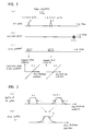
- Fig. 1 is a drawing illustrating an example of pulse sequence SQ' by a conventional spin echo (SE) method.
- a 90° RF pulse R for exciting a desired slice is applied to effect excitation, and then a 180° RF pulse P for exciting the same slice is applied to invert the slice. Then, as shown in Fig. 1(b), a spin echo signal E51 is observed.
- a slice gradient Bg1 where the magnetic field intensity with respect to the position in the slice thickness direction varies at the rate of the inclination angle G1 is added.
- a profile Ar pertaining to the aforementioned 90° RF pulse R takes on a shape relatively close to the ideal rectangular waveform indicated by dotted lines.
- a profile Ap51 pertaining to the aforementioned 180° RF pulse P takes on a shape whose two shoulders are rounded unlike the ideal rectangular form indicated by dotted lines.
- the half power width of each profile is supposed to be the excitation width ⁇ .
- the slice profile F' determined by the product of the aforementioned profile Ar and the aforementioned profile AP51 takes on a rounded shape with both shoulders gently sloped, generating a so-called "slice-leaned" state.
- An object of the present invention is to provide an MR imaging method and an MRI apparatus preventing deterioration in NMR signals due to a slice-leaned state.
- the invention provides an MR imaging method for applying a 180° RF pulse to a specimen after applying a 90° RF pulse to it, characterized in that the excitation width pertaining to the aforementioned 180° RF pulse is made broader than the excitation width pertaining to the aforementioned 90° RF pulse.
- the excitation width pertaining to the 180° RF pulse is made broader than the excitation width pertaining to the 90° RF pulse, the width of the profile pertaining to the 180° RF pulse is expanded in the slice thickness direction.
- the invention provides an MR imaging method of the above-described configuration, characterized in that the excitation width is expanded by making the inclination angle of the gradient magnetic field with respect to the position in the slice thickness direction at the time of applying the 180° RF pulse smaller than the inclination angle of the gradient magnetic field at the time of applying the 90° RF pulse.
- the excitation width is expanded by making the inclination angle of the gradient magnetic field smaller at the time of applying the 180° RF pulse. This is particularly useful where widening of the band of the RF pulse frequency component is restricted.
- the invention provides an MR imaging method of the above-described configuration, characterized in that the excitation width is expanded by reducing the width of the aforementioned 180° RF pulse in the time axis direction.
- the excitation width can be expanded even where the inclination angle of the gradient magnetic field with respect to the position in the slice thickness direction at the time of applying the 180° RF pulse is equal to the inclination angle of the gradient magnetic field at the time of applying the 90° RF pulse, because the frequency component band is made broader by reducing the width of the 180° RF pulse in the time axis direction to expand the excitation width.
- the difference from the inclination angle of the gradient magnetic field at the time of applying the 90° RF pulse, and the control of the gradient magnetic field can be made easier and more precisely.
- the invention provides an MR imaging method of the above-described configuration, characterized in that, where multi-slice imaging is to be accomplished by successively applying a plurality of 180° RF pulses, the excitation width pertaining to the aforementioned 180° RF pulse is made broader than the excitation width pertaining to the aforementioned 90° RF pulse by not smaller than a 0.4-fold multiple but not greater than a 0.6-fold multiple of the slice spacing.
- the NMR signal intensity improving performance due to expansion of the excitation width can be sufficiently achieved because the lower limit of expanding the excitation width pertaining to the 180° RF pulse is made a 0.4-fold multiple of the slice spacing. Furthermore, as the upper limit of expanding the excitation width pertaining to the 180° RF pulse is made a 0.6-fold multiple of the slice spacing, interference between adjoining slice profiles can be reduced.
- the invention provides an MR imaging method of the above-described configuration, characterized in that the excitation width pertaining to an inversion pulse to be applied first out of a pulse sequence is made broader than the excitation width pertaining to the 90° RF pulse.
- NMR signals can be prevented from deterioration by restraining the occurrence of a slice-leaned state.
- IR inversion recovery
- the invention provides an MR imaging method of the above-described configuration, characterized in that the excitation width of the aforementioned 180° RF pulse is expanded so that the whole part excited by the aforementioned 90° RF pulse be excited by the aforementioned 180° RF pulse.
- the best SNR can be obtained.
- the invention provides an MRI apparatus provided with a gradient magnetic field generating unit for generating a gradient magnetic field; an RF pulse transmitting unit for transmitting RF pulses; and an NMR signal receiving unit for receiving NMR signals; and the MRI apparatus being characterized in that it is provided with an excitation width adjusting unit for making the excitation width pertaining to a 180° RF pulse broader than the excitation width pertaining to a 90° RF pulse.
- the MRI apparatus in the aforementioned seventh aspect can appropriately implement the MR imaging method according to the aforementioned first aspect.
- the invention provides an MRI apparatus of the above-described configuration, characterized in that the aforementioned excitation width adjusting unit so controls the operation of the aforementioned gradient magnetic field generating unit as to make the inclination angle of the gradient magnetic field with respect to the position in the slice thickness direction at the time of applying the 180° RF pulse smaller than the inclination angle of the gradient magnetic field at the time of applying the 90° RF pulse.
- the MRI apparatus in the aforementioned eighth aspect can appropriately implement the MR imaging method according to the aforementioned second aspect.
- the invention provides an MRI apparatus of the above-described configuration, characterized in that the aforementioned excitation width adjusting unit so controls the operation of the aforementioned RF pulse transmitting unit as to reduce the width of the aforementioned 180° RF pulse in the time axis direction.
- the MRI apparatus in the aforementioned ninth aspect can appropriately implement the MR imaging method according to the aforementioned third aspect.
- the invention provides an MRI apparatus of the above-described configuration, characterized in that the aforementioned excitation width adjusting unit, where multi-slice imaging is to be accomplished by successively applying a plurality of 180° RF pulses, makes the excitation width pertaining to the aforementioned 180° RF pulse broader than the excitation width pertaining to the aforementioned 90° RF pulse by not smaller than a 0.4-fold multiple but not greater than a 0.6-fold multiple of the slice spacing.
- the MRI apparatus in the aforementioned 10th aspect can appropriately implement the MR imaging method according to the aforementioned fourth aspect.
- the invention provides an MRI apparatus of the above-described configuration, characterized in that the aforementioned excitation width adjusting unit makes the excitation width pertaining to an inversion pulse to be applied first out of a pulse sequence broader than the excitation width pertaining to the 90° RF pulse.
- the MRI apparatus in the aforementioned 11th aspect can appropriately implement the MR imaging method according to the aforementioned fifth aspect.
- the invention provides an MRI apparatus of the above-described configuration, characterized in that the aforementioned excitation width adjusting unit expands the excitation width of the aforementioned 180° RF pulse so that the whole part excited by the aforementioned 90° RF pulse be excited by the aforementioned 180° RF pulse.
- the MRI apparatus in the aforementioned 12th aspect can appropriately implement the MR imaging method according to the aforementioned sixth aspect.
- the MR imaging method and the MRI apparatus according to the present invention makes it possible to obtain a slice profile closed to the ideal rectangular form and to generate MR images of high picture quality by, after exciting a prescribed excitation width with a 90° RF pulse, exciting a broader range than the excitation width with a 180° RF pulse.
- Fig. 1 are diagrams for explaining a pulse sequence by a spin echo method according to the prior art.
- Fig. 2 are diagrams for explaining the principle of generation of a slice-leaned state due to the pulse sequence of Fig. 1.
- Fig. 3 is a block diagram of an MRI apparatus in one embodiment of the invention.
- Fig. 4 is a diagram for explaining a pulse sequence of a spin echo method by the MRI apparatus 100 of Fig. 3.
- Fig. 5 are diagrams for explaining the profile and the slice profile pertaining to the RF pulse of the pulse sequence of Fig. 4.
- Fig. 6 is a graph typically showing variations in signal intensity when single-slice imaging is performed.
- Fig. 7 is a graph typically showing variations in sub.SNR when single-slice imaging is performed.
- Fig. 8 are diagrams for explaining a pulse sequence SQ1 when multi-slice imaging is performed with the MRI apparatus 100 of Fig. 3.
- Fig. 9 is a graph typically showing variations in signal intensity when multi-slice imaging is performed.
- Fig. 10 are diagrams for explaining a pulse sequence by an inversion recovery method in another embodiment of the invention.
- Fig. 11 are diagrams for explaining a pulse sequence by a spin echo method in still another still another embodiment of the invention.
- Fig. 3 is a block diagram of an MRI apparatus in one mode of implementing the invention.
- a magnet assembly 1 has a space part (hole) for inserting a specimen into the inside, and surrounding this space part there are arranged a permanent magnet 1p for applying a static magnetic field of a certain intensity Ho to the specimen; a gradient magnetic field coil 1g for applying gradient pulses to a slice gradient shaft, a phase gradient shaft and a read gradient shaft; a transmission coil 1t for providing an RF pulse to excite the spinning of atomic nuclei in the specimen; and a reception coil 1r for detecting NMR signals from the specimen.
- the aforementioned gradient magnetic field coil 1g, transmission coil 1t and reception coil 1r are respectively connected to a gradient magnetic field drive circuit 3, an RF power amplifier 4 and a preamplifier 5.
- a superconducting magnet or a normally conducting magnet may be used as well.
- a sequence memory circuit 8 in accordance with an instruction a computer 7, operates the gradient magnetic field drive circuit 3 on the basis of a pulse sequence that is stored to apply a gradient pulse from the gradient magnetic field coil 1g of the aforementioned magnet assembly 1, and at the same time operates a gate modulation circuit 9 to modulate carrier output signals of an RF oscillation circuit 10 into pulse-shaped signals of a prescribed timing and a prescribed envelope shape. These signals are applied to the RF power amplifier 4 as RF pulses, and after being amplified in power by the RF power amplifier 4, applied to the transmission coil 1t of the aforementioned magnet assembly 1 to excite a desired slice area.
- the preamplifier 5 amplifies NMR signals out of the specimen detected by the reception coil 1r of the magnet assembly 1, and inputs them to a phase detector 12.
- the phase detector 12 with the carrier output signals from the RF oscillation circuit 10 as reference signals, phase-detects the NMR signals from the preamplifier 5, and provides them to an A/D converter 11.
- the A/D converter 11 converts phase-detected analog signals into digital signals, and inputs them to the computer 7.
- the computer 7 reads data from the A/D converter 11, and subjects them to computation for image reconfiguration to generate an image of the desired slide area. This image is displayed on a display unit 6.
- the computer 7 is responsible for overall control, including acceptance of information inputted from an operating unit 13.
- Fig. 4 is a diagram for explaining a pulse sequence SQ of a spin echo method by the MRI apparatus 100 of Fig. 3.
- excitation is accomplished by applying a 90° RF pulse R for exciting a desired slice, and then it is inverted by applying a 180° RF pulse P for exciting the aforementioned desired slice. Then, as shown in Fig. 4(b), a spin echo signal E is observed.
- a slice gradient Bg1 where the magnetic field intensity with respect to the position in the slice thickness direction varies at the rate of an inclination angle G1 is added.
- a slice gradient Bg2 where the magnetic field intensity with respect to the position in the slice thickness direction varies at the rate of an inclination angle G2 (G2 ⁇ G1) is added.
- a profile AP1 pertaining to the aforementioned 180° RF pulse P is broader than the profile AP51 pertaining to the conventional pulse sequence SQ' (see Fig. 2) in the slice thickness direction.
- the excitation width ⁇ 1 is broader than the excitation width ⁇ pertaining to the aforementioned profile Ap51 by an additional excitation width Sp.
- Fig. 5(b) it is made possible restrain the slice profile F from falling into a slice-leaned state and thereby prevent the spin echo signal E from dropping in intensity.
- the slice thickness SL pertaining to the slice profile F does not expand excessively as it is limited by the aforementioned profile Ap1.
- Fig. 6 is a graph typically showing variations in the intensity of the spin echo signal E (a standardized percentage with the signal intensity at an additional excitation width SP of 0 being the reference) relative to [the additional excitation width Sp/the slice thickness SL] when single-slice imaging is performed with the pulse sequence SQ of Fig. 4.
- Fig. 7 is a graph typically showing variations in sub.SNR (SNR obtained, after observing the spin echo signal E twice, from its dispersion and signal intensity) relative to the aforementioned [Sp/SL].
- the slice thickness SL is 5[mm].
- the echo time TE is the minfull (the minimum TE that can be set without fractional echo).
- the repeat time TR is 500 ms.
- Fig. 8 consists of diagrams for explaining a pulse sequence SQ1 when multi-slice imaging is with the MRI apparatus 100 of Fig. 3.
- the slice gradient Bg1 where the magnetic field intensity with respect to the position in the slice thickness direction varies at the rate of the inclination angle G1 is added.
- the slice gradient Bg2 where the magnetic field intensity with respect to the position in the slice thickness direction varies at the rate of the inclination angle G2 (G2 ⁇ G1) is added.
- the D.C. component of the slice gradient Bg2 slightly for each of the 180° RF pulses P1, P2, P3,...
- Fig. 9 is a graph typically showing variations in the intensity of echo signals relative to [the additional excitation width SP/the slice thickness SL] when multi-slice imaging is performed with the pulse sequence SQ1 of Fig. 8.
- the slice thickness SL is 5[mm].
- the slice spacing is 5[mm].
- the echo time TE is minfull.
- the repeat time TR is 500 ms.
- the quantity of width expansion of the profile pertaining to the 180° RF pulses P1, P2, P3, ... is relatively small and insufficient for restraining a slice-leaned state.
- the aforementioned [SP/SL] is greater than 0.6, interference occurs between adjoining slice profiles under the influence of the ripple component of each slice profile.
- the above-described MRI apparatus 100 may as well be modified as follows.
Landscapes
- Physics & Mathematics (AREA)
- Health & Medical Sciences (AREA)
- Life Sciences & Earth Sciences (AREA)
- High Energy & Nuclear Physics (AREA)
- Condensed Matter Physics & Semiconductors (AREA)
- General Physics & Mathematics (AREA)
- Nuclear Medicine, Radiotherapy & Molecular Imaging (AREA)
- Engineering & Computer Science (AREA)
- Molecular Biology (AREA)
- Pathology (AREA)
- Radiology & Medical Imaging (AREA)
- Biomedical Technology (AREA)
- Heart & Thoracic Surgery (AREA)
- Medical Informatics (AREA)
- Biophysics (AREA)
- Surgery (AREA)
- Animal Behavior & Ethology (AREA)
- General Health & Medical Sciences (AREA)
- Public Health (AREA)
- Veterinary Medicine (AREA)
- Magnetic Resonance Imaging Apparatus (AREA)
Abstract
Description
Claims (12)
- An MR imaging method comprising the steps of:applying a 90° RF pulse to a specimen; andapplying a 180° RF pulse to said specimen, the excitation width pertaining to the 180° RF pulse being made broader than the excitation width pertaining to the 90° RF pulse.
- The MR imaging method of claim 1, wherein the excitation width is expanded by making the inclination angle of the gradient magnetic field with respect to the position in the slice thickness direction at the time of applying the 180° RF pulse smaller than the inclination angle of the gradient magnetic field at the time of applying the 90° RF pulse.
- The MR imaging method of claim 1, wherein the excitation width is expanded by reducing the width of the 180° RF pulse in the time axis direction.
- The MR imaging method of claim 1, wherein where multi-slice imaging is to be accomplished by successively applying a plurality of 180° RF pulses, the excitation width pertaining to the 180° RF pulse is made broader than the excitation width pertaining to the 90° RF pulse by not smaller than a 0.4-fold multiple but not greater than a 0.6-fold multiple of the slice spacing.
- The MR imaging method of claim 1, wherein the excitation width pertaining to an inversion pulse to be applied first out of a pulse sequence is made broader than the excitation width pertaining to the 90° RF pulse.
- The MR imaging method of claim 1, wherein the excitation width of the 180° RF pulse is expanded so that the whole part excited by the 90° RF pulse is excited by the 180° RF pulse.
- An MRI apparatus comprising:wherein there is provided with an excitation width adjusting unit for making the excitation width pertaining to a 180° RF pulse broader than the excitation width pertaining to a 90° RF pulse.a gradient magnetic field generating unit for generating a gradient magnetic field;an RF pulse transmitting unit for transmitting RF pulses; andan NMR signal receiving unit for receiving NMR signals;
- The MRI apparatus of claim 7, wherein the excitation width adjusting unit so controls the operation of the gradient magnetic field generating unit as to make the inclination angle of the gradient magnetic field with respect to the position in the slice thickness direction at the time of applying the 180° RF pulse smaller than the inclination angle of the gradient magnetic field at the time of applying the 90° RF pulse.
- The MRI apparatus of claim 7, wherein the excitation width adjusting unit so controls the operation of the RF pulse transmitting unit as to reduce the width of the 180° RF pulse in the time axis direction.
- The MRI apparatus of claim 7, wherein the excitation width adjusting unit, where multi-slice imaging is to be accomplished by successively applying a plurality of 180° RF pulses, makes the excitation width pertaining to the 180° RF pulse broader than the excitation width pertaining to the 90° RF pulse by not smaller than a 0.4-fold multiple but not greater than a 0.6-fold multiple of the slice spacing.
- The MRI apparatus of claim 7, wherein the excitation width adjusting unit makes the excitation width pertaining to an inversion pulse to be applied first out of a pulse sequence broader than the excitation width pertaining to the 90° RF pulse.
- The MRI apparatus of claim 7, wherein the excitation width adjusting unit expands the excitation width of the 180° RF pulse so that the whole part excited by the 90° RF pulse is excited by the 180° RF pulse.
Applications Claiming Priority (2)
| Application Number | Priority Date | Filing Date | Title |
|---|---|---|---|
| JP2000067313A JP2001258863A (en) | 2000-03-10 | 2000-03-10 | Magnetic resonance imaging method and magnetic resonance imaging device |
| JP2000067313 | 2000-03-10 |
Publications (2)
| Publication Number | Publication Date |
|---|---|
| EP1132753A2 true EP1132753A2 (en) | 2001-09-12 |
| EP1132753A3 EP1132753A3 (en) | 2003-07-23 |
Family
ID=18586527
Family Applications (1)
| Application Number | Title | Priority Date | Filing Date |
|---|---|---|---|
| EP01302160A Withdrawn EP1132753A3 (en) | 2000-03-10 | 2001-03-09 | MR imaging method and MRI apparatus |
Country Status (5)
| Country | Link |
|---|---|
| US (1) | US6489764B2 (en) |
| EP (1) | EP1132753A3 (en) |
| JP (1) | JP2001258863A (en) |
| KR (1) | KR20010089239A (en) |
| CN (1) | CN1243514C (en) |
Cited By (1)
| Publication number | Priority date | Publication date | Assignee | Title |
|---|---|---|---|---|
| NL1034804C2 (en) * | 2006-12-07 | 2012-05-02 | Ge Med Sys Global Tech Co Llc | MAGNETIC RESONANCE IMAGE EQUIPMENT AND MAGNETIC RESONANCE IMAGE METHOD. |
Families Citing this family (8)
| Publication number | Priority date | Publication date | Assignee | Title |
|---|---|---|---|---|
| JP2003038456A (en) * | 2001-07-10 | 2003-02-12 | Ge Medical Systems Global Technology Co Llc | Spin excitation method, magnetic resonance photographing method and magnetic resonance photographing device |
| JP3796446B2 (en) | 2002-01-23 | 2006-07-12 | ジーイー・メディカル・システムズ・グローバル・テクノロジー・カンパニー・エルエルシー | MRI equipment |
| JP3869337B2 (en) * | 2002-08-20 | 2007-01-17 | ジーイー・メディカル・システムズ・グローバル・テクノロジー・カンパニー・エルエルシー | Magnetic resonance imaging device |
| JP2006075380A (en) * | 2004-09-10 | 2006-03-23 | Ge Medical Systems Global Technology Co Llc | Method of generating mr image and mri apparatus |
| DE102005014216B4 (en) * | 2005-03-29 | 2007-01-11 | Siemens Ag | Regional saturation pulses with location-dependent application to minimize the chemical shift artefact |
| CN107092002A (en) * | 2012-11-27 | 2017-08-25 | 朱宇东 | A kind of method of change in time and space using the real-time performance electromagnetic field with electric current carrying pathway |
| DE102014220328B3 (en) * | 2014-10-07 | 2015-08-27 | Sirona Dental Systems Gmbh | Creating an MRI scan |
| JP7610958B2 (en) | 2020-11-04 | 2025-01-09 | キヤノンメディカルシステムズ株式会社 | Magnetic resonance imaging apparatus, imaging parameter determination method, and imaging parameter determination program |
Family Cites Families (13)
| Publication number | Priority date | Publication date | Assignee | Title |
|---|---|---|---|---|
| US4471306A (en) * | 1982-02-03 | 1984-09-11 | General Electric Company | Method of NMR imaging which overcomes T2 * effects in an inhomogeneous static magnetic field |
| US4573015A (en) * | 1982-08-31 | 1986-02-25 | Asahikawa Medical College | Method of measuring internal information from a target by using nuclear magnetic resonance |
| US4746863A (en) * | 1985-11-07 | 1988-05-24 | The Regents Of The University Of California | Contiguous slices in multi-slice MRI |
| JPS62197046A (en) * | 1986-02-25 | 1987-08-31 | 三菱電機株式会社 | Nuclear magnetic resonance imaging method |
| US4803432A (en) * | 1987-08-13 | 1989-02-07 | Wisconsin Alumni Research Foundation | Short echo NMR imaging of sodium |
| JPH03103236A (en) * | 1989-09-18 | 1991-04-30 | Hitachi Ltd | Nuclear magnetic resonance multiecho photographing method |
| JPH05300895A (en) * | 1991-07-31 | 1993-11-16 | Hitachi Medical Corp | Selective excitation method of nuclear spin in mri apparatus |
| JP3174113B2 (en) * | 1991-11-26 | 2001-06-11 | ジーイー横河メディカルシステム株式会社 | MRI equipment |
| CA2226263C (en) * | 1995-07-11 | 2007-08-14 | British Technology Group Limited | Apparatus for and method of nuclear quadrupole testing of a sample |
| US6304084B1 (en) * | 1997-04-14 | 2001-10-16 | The Board Of Trustees Of The Leland Stanford Junior University | Method of improved magnetic resonance spectroscopic localization using spectral-spatial pulses |
| DE19834698C2 (en) * | 1997-08-19 | 2001-06-21 | Siemens Ag | Diffusion detection using magnetic resonance |
| JP3073183B2 (en) * | 1997-09-16 | 2000-08-07 | 技術研究組合医療福祉機器研究所 | Magnetic resonance equipment |
| US6188219B1 (en) * | 1999-01-22 | 2001-02-13 | The Johns Hopkins University | Magnetic resonance imaging method and apparatus and method of calibrating the same |
-
2000
- 2000-03-10 JP JP2000067313A patent/JP2001258863A/en active Pending
-
2001
- 2001-02-08 US US09/779,291 patent/US6489764B2/en not_active Expired - Fee Related
- 2001-03-09 KR KR1020010012219A patent/KR20010089239A/en not_active Ceased
- 2001-03-09 EP EP01302160A patent/EP1132753A3/en not_active Withdrawn
- 2001-03-10 CN CNB011173181A patent/CN1243514C/en not_active Expired - Fee Related
Cited By (1)
| Publication number | Priority date | Publication date | Assignee | Title |
|---|---|---|---|---|
| NL1034804C2 (en) * | 2006-12-07 | 2012-05-02 | Ge Med Sys Global Tech Co Llc | MAGNETIC RESONANCE IMAGE EQUIPMENT AND MAGNETIC RESONANCE IMAGE METHOD. |
Also Published As
| Publication number | Publication date |
|---|---|
| JP2001258863A (en) | 2001-09-25 |
| CN1243514C (en) | 2006-03-01 |
| KR20010089239A (en) | 2001-09-29 |
| US20010021795A1 (en) | 2001-09-13 |
| US6489764B2 (en) | 2002-12-03 |
| CN1313067A (en) | 2001-09-19 |
| EP1132753A3 (en) | 2003-07-23 |
Similar Documents
| Publication | Publication Date | Title |
|---|---|---|
| JP3117670B2 (en) | Multi-slice MR imaging method and MRI apparatus | |
| US7538550B2 (en) | Magnetic resonance imaging apparatus, magnetic resonance imaging method, scan apparatus, program and storage medium | |
| JP3796455B2 (en) | MRI equipment | |
| US8054078B2 (en) | Parallel imaging method and MRI apparatus | |
| US6489764B2 (en) | MR method and apparatus for making broader the 180° excitation width | |
| US6559643B2 (en) | Magnetic resonance method and apparatus which measures residual magnetization from two or more orderly height reduce gradient pulses, of alternately inverted polarity, applied prior to the transmitting of rf pulses | |
| JP2009160342A (en) | Magnetic resonance imaging apparatus, and rf pulse transmission method and program | |
| US6470203B2 (en) | MR imaging method, phase error measuring method and MRI system | |
| JP3028220B2 (en) | MRI equipment | |
| EP1653244B1 (en) | Ghost artifact reduction in fast spin echo MRI sequences | |
| US7405566B2 (en) | RF pulse applying method and MRI apparatus | |
| US5685304A (en) | Diffusion sensitizing imaging method and MRI apparatus | |
| JP2002143115A (en) | Mr imaging method, method for measuring phase error mri equipment | |
| JP4795565B2 (en) | MR data collection method and MRI apparatus | |
| CN101002677A (en) | RF pulse applying method and mri apparatus | |
| JP3447099B2 (en) | MRI equipment | |
| JP3884283B2 (en) | MRI equipment | |
| JPH06205754A (en) | Preparation pulse applying method for mr system | |
| JP3310751B2 (en) | Asymmetric RF pulse generation method and MRI apparatus | |
| JP3432593B2 (en) | MRI equipment | |
| JPH10277002A (en) | Mr continuous image pickup method and mri device | |
| JP2000185026A (en) | Mr imaging method and device | |
| JP4489278B2 (en) | Diffusion weighted imaging method and MRI apparatus | |
| JPH10248824A (en) | Diffusion accentuated imaging method and mri system | |
| JPH0824235A (en) | Method for collecting data in mri appparatus, and mri apparatus |
Legal Events
| Date | Code | Title | Description |
|---|---|---|---|
| PUAI | Public reference made under article 153(3) epc to a published international application that has entered the european phase |
Free format text: ORIGINAL CODE: 0009012 |
|
| AK | Designated contracting states |
Kind code of ref document: A2 Designated state(s): AT BE CH CY DE DK ES FI FR GB GR IE IT LI LU MC NL PT SE TR |
|
| AX | Request for extension of the european patent |
Free format text: AL;LT;LV;MK;RO;SI |
|
| PUAL | Search report despatched |
Free format text: ORIGINAL CODE: 0009013 |
|
| AK | Designated contracting states |
Designated state(s): AT BE CH CY DE DK ES FI FR GB GR IE IT LI LU MC NL PT SE TR |
|
| AX | Request for extension of the european patent |
Extension state: AL LT LV MK RO SI |
|
| 17P | Request for examination filed |
Effective date: 20040123 |
|
| AKX | Designation fees paid |
Designated state(s): DE FR GB |
|
| 17Q | First examination report despatched |
Effective date: 20070723 |
|
| STAA | Information on the status of an ep patent application or granted ep patent |
Free format text: STATUS: THE APPLICATION IS DEEMED TO BE WITHDRAWN |
|
| 18D | Application deemed to be withdrawn |
Effective date: 20071204 |