EP1132686A1 - Methods and apparatus for reducing heat load in combustor panels - Google Patents
Methods and apparatus for reducing heat load in combustor panels Download PDFInfo
- Publication number
- EP1132686A1 EP1132686A1 EP01301843A EP01301843A EP1132686A1 EP 1132686 A1 EP1132686 A1 EP 1132686A1 EP 01301843 A EP01301843 A EP 01301843A EP 01301843 A EP01301843 A EP 01301843A EP 1132686 A1 EP1132686 A1 EP 1132686A1
- Authority
- EP
- European Patent Office
- Prior art keywords
- panel
- panels
- liner
- thermal barrier
- barrier material
- Prior art date
- Legal status (The legal status is an assumption and is not a legal conclusion. Google has not performed a legal analysis and makes no representation as to the accuracy of the status listed.)
- Granted
Links
- 238000000034 method Methods 0.000 title claims description 13
- 239000000463 material Substances 0.000 claims abstract description 85
- 230000004888 barrier function Effects 0.000 claims abstract description 81
- 238000001816 cooling Methods 0.000 claims abstract description 24
- 238000002485 combustion reaction Methods 0.000 claims abstract description 14
- 238000011144 upstream manufacturing Methods 0.000 claims description 2
- 239000000567 combustion gas Substances 0.000 description 13
- 239000000446 fuel Substances 0.000 description 9
- 239000007789 gas Substances 0.000 description 6
- 230000001681 protective effect Effects 0.000 description 4
- 239000012720 thermal barrier coating Substances 0.000 description 4
- 239000000203 mixture Substances 0.000 description 3
- 238000010521 absorption reaction Methods 0.000 description 1
- 230000000712 assembly Effects 0.000 description 1
- 238000000429 assembly Methods 0.000 description 1
- 239000000284 extract Substances 0.000 description 1
- 239000010408 film Substances 0.000 description 1
- 238000009413 insulation Methods 0.000 description 1
- VEMKTZHHVJILDY-UHFFFAOYSA-N resmethrin Chemical compound CC1(C)C(C=C(C)C)C1C(=O)OCC1=COC(CC=2C=CC=CC=2)=C1 VEMKTZHHVJILDY-UHFFFAOYSA-N 0.000 description 1
- 239000010409 thin film Substances 0.000 description 1
Images

Classifications
-
- F—MECHANICAL ENGINEERING; LIGHTING; HEATING; WEAPONS; BLASTING
- F23—COMBUSTION APPARATUS; COMBUSTION PROCESSES
- F23R—GENERATING COMBUSTION PRODUCTS OF HIGH PRESSURE OR HIGH VELOCITY, e.g. GAS-TURBINE COMBUSTION CHAMBERS
- F23R3/00—Continuous combustion chambers using liquid or gaseous fuel
- F23R3/002—Wall structures
-
- F—MECHANICAL ENGINEERING; LIGHTING; HEATING; WEAPONS; BLASTING
- F23—COMBUSTION APPARATUS; COMBUSTION PROCESSES
- F23R—GENERATING COMBUSTION PRODUCTS OF HIGH PRESSURE OR HIGH VELOCITY, e.g. GAS-TURBINE COMBUSTION CHAMBERS
- F23R3/00—Continuous combustion chambers using liquid or gaseous fuel
- F23R3/02—Continuous combustion chambers using liquid or gaseous fuel characterised by the air-flow or gas-flow configuration
- F23R3/04—Air inlet arrangements
- F23R3/06—Arrangement of apertures along the flame tube
- F23R3/08—Arrangement of apertures along the flame tube between annular flame tube sections, e.g. flame tubes with telescopic sections
-
- F—MECHANICAL ENGINEERING; LIGHTING; HEATING; WEAPONS; BLASTING
- F23—COMBUSTION APPARATUS; COMBUSTION PROCESSES
- F23R—GENERATING COMBUSTION PRODUCTS OF HIGH PRESSURE OR HIGH VELOCITY, e.g. GAS-TURBINE COMBUSTION CHAMBERS
- F23R2900/00—Special features of, or arrangements for continuous combustion chambers; Combustion processes therefor
- F23R2900/00005—Preventing fatigue failures or reducing mechanical stress in gas turbine components
-
- Y—GENERAL TAGGING OF NEW TECHNOLOGICAL DEVELOPMENTS; GENERAL TAGGING OF CROSS-SECTIONAL TECHNOLOGIES SPANNING OVER SEVERAL SECTIONS OF THE IPC; TECHNICAL SUBJECTS COVERED BY FORMER USPC CROSS-REFERENCE ART COLLECTIONS [XRACs] AND DIGESTS
- Y02—TECHNOLOGIES OR APPLICATIONS FOR MITIGATION OR ADAPTATION AGAINST CLIMATE CHANGE
- Y02T—CLIMATE CHANGE MITIGATION TECHNOLOGIES RELATED TO TRANSPORTATION
- Y02T50/00—Aeronautics or air transport
- Y02T50/60—Efficient propulsion technologies, e.g. for aircraft
-
- Y—GENERAL TAGGING OF NEW TECHNOLOGICAL DEVELOPMENTS; GENERAL TAGGING OF CROSS-SECTIONAL TECHNOLOGIES SPANNING OVER SEVERAL SECTIONS OF THE IPC; TECHNICAL SUBJECTS COVERED BY FORMER USPC CROSS-REFERENCE ART COLLECTIONS [XRACs] AND DIGESTS
- Y10—TECHNICAL SUBJECTS COVERED BY FORMER USPC
- Y10T—TECHNICAL SUBJECTS COVERED BY FORMER US CLASSIFICATION
- Y10T29/00—Metal working
- Y10T29/49—Method of mechanical manufacture
- Y10T29/49346—Rocket or jet device making
Definitions
- This invention relates generally to turbine engines, and, more particularly, to slot cooled ring combustors for turbine engines.
- a turbine engine includes a compressor for compressing air which is mixed with a fuel and channeled to a combustor wherein the mixture is ignited for generating hot combustion gases.
- the combustion gases are channeled to a turbine, which extracts energy from the combustion gases for powering the compressor, as well as producing useful work to propel an aircraft in flight or to power a load, such as an electrical generator.
- Increased efficiency in gas turbine engines is accomplished at least in part by an increase in the operating temperature of the combustor.
- a limitation on the operating combustor temperature is a temperature limitation of combustor liner material.
- Thin film convection cooling can be used to cool a combustor liner. With such cooling, a protective film boundary of cool air flows along an inner surface of the liner. The cool air flowing along the combustor liner inner surface forms a protective boundary between the liner and the hot gases, and insulates the liner from hot combustion gases. See, for example, U.S. Patent No. 4,259,842. Even with such cooling, however, the liner materials absorb heat. Over time, thermal creep and low cycle fatigue increase in the liner.
- a thermal barrier coating also can be applied to inner surfaces of the combustor liner for providing thermal insulation against combustion gases.
- Thermal barrier coatings reduce an amount of cooling air required for a given combustion gas temperature, or allow an increase in a combustion gas temperature for increasing efficiency of the engine. See, for example, U.S. Patent No. 5,960,632.
- the thermal barrier coating is applied uniformly across the combustor liner with a thickness of 0.01 inches or less. Such a uniform thickness prevents the thermal barrier coating from undesirably building-up to potentially obstruct the flow of cooling air.
- the combustor liner materials still absorb heat, and thus, combustor assemblies are still subjected to thermal strains including creep and low cycle fatigue.
- a combustor in an exemplary embodiment of the invention, includes a combustor liner with a thermal barrier material that has a thickness selected to minimize heat absorption.
- the combustor includes a combustion zone formed by annular outer and inner supporting members and respective inner and outer liners.
- the inner and outer liners each include a series of panels and a plurality of cooling slots. The panels are arranged in steps relative to one another and form a stepped combustor liner surface.
- the plurality of cooling slots are formed by overhanging portions of the inner and outer liner panels.
- At least one portion of the combustor liner has a thermal barrier material with a thickness greater than 0.01 inches.
- at least the outer and inner liner panels adjacent an inlet of the combustor have a thermal barrier material with a thickness greater than 0.01 inches.
- the combustor liner material absorbs less heat, and therefore, at present day operating temperatures, the combustor may be operated at higher temperatures. Because the operating temperature is reduced, low cycle fatigue within the combustor is also reduced which, in turn, extends an operating life cycle of the combustor assembly.
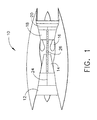
- Figure 1 is a schematic illustration of a gas turbine engine 10 including a low pressure compressor 12, a high pressure compressor 14, and a combustor assembly 16.
- Engine 10 also includes a high pressure turbine 18, and a low pressure turbine 20.
- Compressor 12 and turbine 20 are coupled by a first shaft 24, and compressor 14 and turbine 18 are coupled by a second shaft 26.
- engine 10 is a CF34-3A/-3B engine available from General Electric Aircraft Engines, Cincinnati, Ohio.
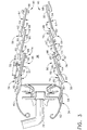
- FIG 2 is a partial cross-sectional view of combustor assembly 16 including a combustor 30 and a fuel injector 32.
- Figure 3 is an enlarged view of a portion of combustor assembly 16.
- Fuel injector 32 is attached to an inlet 34 of combustor assembly 16 and injects atomized fuel into a combustion zone 36 of combustor 30 to form an air-fuel mixture.
- An igniter or cross-fire tube (not shown) ignites the air-fuel mixture downstream of fuel injector 32, and combustion gases exit combustor assembly 16 through an outlet turbine nozzle 38 that directs high energy combustion gases towards a row of turbine blades or buckets (not shown).
- the combustion gases rotate a turbine wheel (not shown) that delivers rotational energy to a compressor (not shown), powers a load, and/or is converted into thrust.
- Combustion zone 36 is formed by annular, radially outer and radially inner supporting members (not shown) and a combustor liner 40.
- Combustor liner 40 shields the outer and inner supporting members from the heat generated within combustion zone 36 and includes an outer liner 50 and an inner liner 52.
- Outer liner 50 and inner liner 52 are annular and connect together to define combustion zone 36.
- Combustion zone 36 extends from combustor inlet 34 to outlet turbine nozzle 38.
- Outer and inner liners 50 and 52 each include a plurality of panels 54 which include a series of steps 56, each of which form a distinct portion of combustor liner 40.
- Outer liner 50 and inner liner 52 each include a cowl 60 and 62, respectively, and a first panel 64 and 66, respectively.
- Inner cowl 60 and outer cowl 62 are positioned adjacent combustor inlet 34 and extend from combustor inlet 34 to first panels 64 and 66, respectively.
- First panels 64 and 66 are connected serially downstream from cowls 60 and 62, respectively, and each are connected between cowls 60 and 62, respectively, and additional outer and inner liner panels 54.
- outer liner 50 and inner liner 52 each include nine panels 54.
- Each combustor panel 54 includes a combustor liner surface 70, an exterior surface 72, and an overhang portion 74.
- Combustor liner surface 70 is extends from combustor inlet 34 to outlet turbine nozzle 38.
- Combustor liner surface 70 and exterior surface 72 are connected together at overhang portion 74 and form a rear facing edge 76.
- a plurality of air cooling slots 78 separate adjacent combustor panels 54.
- Air cooling slots 78 include openings 80 to receive air from an air plenum (not shown) and form a thin protective boundary of air between high temperature combustion gases and combustor liner surface 70, as well as providing for convective cooling of combustor liner 40. Air flows from openings 80 through slots 78 formed between combustor liner surface 70 and a bottom surface 82 of combustor liner overhang portions 74.
- a layer 90 of thermal barrier material is applied on combustor liner surface 70 and extends from overhang portion 74 to overhang portion 74 of each step 54.
- Thermal barrier material further insulates combustor liner surface 70 from high temperature combustion gases.
- thermal barrier material is commercially available from Englehart Industries, Wilmington Massachusetts.
- Thermal barrier material is applied to combustor liner surface 70 over each combustor panel 54 disposed between combustor inlet 34 and combustor outlet turbine nozzle 38.
- Thermal barrier material is applied such that layer 90 has a thickness T 1 greater than 0.01 inches extending over at least a portion 96 of combustor liner surface 70.
- portion 96 includes only outer liner first panel 64 and inner liner first panel 66 and any remaining panels 54 have a layer 90 of thermal barrier material with a thickness T 2 of 0.01 inches or less.
- portion 96 includes outer and inner liner first panels 64 and 66, and at least one other outer liner panel 54 and inner liner panel 54, and any remaining panels 54 have thermal barrier material with thickness T 2 is 0.01 inches or less.
- combustor liner surface 70 thermal barrier material is applied such that layer 90 extends over all combustor panels 54 between combustor inlet 34 and combustor outlet turbine nozzle 38 and has thickness T 1 greater than 0.01 inches.
- Thickness T 1 is measured from combustor liner surface 70 to a top surface 98 of layer 90.
- layer 90 extends over portion 96 and has thickness T 1 approximately twice thickness T 2 of thermal barrier material extending over panels 54 not in portion 96.
- thermal barrier material thickness T 1 is between 0.20 and 0.35 inches and thickness T 2 is 0.01 inches or less. In a further embodiment, thermal barrier material thickness T 1 is approximately 0.20 inches.
- portion 96 has thermal barrier material with a thickness T 1 , less heat is absorbed into panels 54 within combustor portion 96 and an operating temperature of combustor 30 is lowered, thus reducing an amount of thermal strains within combustor assembly 16.
- the above-described combustor assembly is cost-effective and highly reliable.
- the combustor assembly includes a thermal barrier material having a thickness greater than 0.01 inches covering at least a portion of the combustor liner. As a result, the combustor liner absorbs less heat, and therefore, the combustor may be operated at higher temperatures. Because the operating temperature is reduced, low cycle fatigue within the combustor is reduced, which in turn, extends an operating life cycle for the combustor assembly.
Landscapes
- Engineering & Computer Science (AREA)
- Chemical & Material Sciences (AREA)
- Combustion & Propulsion (AREA)
- Mechanical Engineering (AREA)
- General Engineering & Computer Science (AREA)
- Turbine Rotor Nozzle Sealing (AREA)
- Gas Burners (AREA)
- Solid Fuels And Fuel-Associated Substances (AREA)
Abstract
Description
- This invention relates generally to turbine engines, and, more particularly, to slot cooled ring combustors for turbine engines.
- A turbine engine includes a compressor for compressing air which is mixed with a fuel and channeled to a combustor wherein the mixture is ignited for generating hot combustion gases. The combustion gases are channeled to a turbine, which extracts energy from the combustion gases for powering the compressor, as well as producing useful work to propel an aircraft in flight or to power a load, such as an electrical generator. Increased efficiency in gas turbine engines is accomplished at least in part by an increase in the operating temperature of the combustor. A limitation on the operating combustor temperature is a temperature limitation of combustor liner material.
- Thin film convection cooling can be used to cool a combustor liner. With such cooling, a protective film boundary of cool air flows along an inner surface of the liner. The cool air flowing along the combustor liner inner surface forms a protective boundary between the liner and the hot gases, and insulates the liner from hot combustion gases. See, for example, U.S. Patent No. 4,259,842. Even with such cooling, however, the liner materials absorb heat. Over time, thermal creep and low cycle fatigue increase in the liner.
- A thermal barrier coating also can be applied to inner surfaces of the combustor liner for providing thermal insulation against combustion gases. Thermal barrier coatings reduce an amount of cooling air required for a given combustion gas temperature, or allow an increase in a combustion gas temperature for increasing efficiency of the engine. See, for example, U.S. Patent No. 5,960,632. Typically the thermal barrier coating is applied uniformly across the combustor liner with a thickness of 0.01 inches or less. Such a uniform thickness prevents the thermal barrier coating from undesirably building-up to potentially obstruct the flow of cooling air. However, the combustor liner materials still absorb heat, and thus, combustor assemblies are still subjected to thermal strains including creep and low cycle fatigue.
- In an exemplary embodiment of the invention, a combustor includes a combustor liner with a thermal barrier material that has a thickness selected to minimize heat absorption. In the exemplary embodiment, the combustor includes a combustion zone formed by annular outer and inner supporting members and respective inner and outer liners. The inner and outer liners each include a series of panels and a plurality of cooling slots. The panels are arranged in steps relative to one another and form a stepped combustor liner surface. The plurality of cooling slots are formed by overhanging portions of the inner and outer liner panels. At least one portion of the combustor liner has a thermal barrier material with a thickness greater than 0.01 inches. In the exemplary embodiment, at least the outer and inner liner panels adjacent an inlet of the combustor have a thermal barrier material with a thickness greater than 0.01 inches.
- As a result of the additional thickness of thermal barrier material applied to at least a portion of the combustor liner, the combustor liner material absorbs less heat, and therefore, at present day operating temperatures, the combustor may be operated at higher temperatures. Because the operating temperature is reduced, low cycle fatigue within the combustor is also reduced which, in turn, extends an operating life cycle of the combustor assembly.
- An embodiment of the invention will now be described, by way of example, with reference to the accompanying drawings, in which:
- Figure 1 is a schematic illustration of a gas turbine engine;
- Figure 2 is partial cross-sectional view of a combustor assembly used with the gas turbine engine shown in Figure 1; and
- Figure 3 is an enlarged view of a portion of the combustor assembly shown in
Figure 2 taken along
area 2. -
- Figure 1 is a schematic illustration of a
gas turbine engine 10 including alow pressure compressor 12, ahigh pressure compressor 14, and acombustor assembly 16.Engine 10 also includes ahigh pressure turbine 18, and alow pressure turbine 20.Compressor 12 andturbine 20 are coupled by afirst shaft 24, andcompressor 14 andturbine 18 are coupled by asecond shaft 26. In one embodiment,engine 10 is a CF34-3A/-3B engine available from General Electric Aircraft Engines, Cincinnati, Ohio. - In operation, air flows through
low pressure compressor 12 from an inlet side 28 ofengine 10 and compressed air is supplied fromlow pressure compressor 12 tohigh pressure compressor 14. Compressed air is then delivered tocombustor assembly 16 where it is mixed with fuel an ignited. The combustion gases are channeled fromcombustor 16 to driveturbines - Figure 2 is a partial cross-sectional view of
combustor assembly 16 including acombustor 30 and afuel injector 32. Figure 3 is an enlarged view of a portion ofcombustor assembly 16.Fuel injector 32 is attached to aninlet 34 ofcombustor assembly 16 and injects atomized fuel into acombustion zone 36 ofcombustor 30 to form an air-fuel mixture. An igniter or cross-fire tube (not shown) ignites the air-fuel mixture downstream offuel injector 32, and combustion gasesexit combustor assembly 16 through anoutlet turbine nozzle 38 that directs high energy combustion gases towards a row of turbine blades or buckets (not shown). The combustion gases rotate a turbine wheel (not shown) that delivers rotational energy to a compressor (not shown), powers a load, and/or is converted into thrust. -
Combustion zone 36 is formed by annular, radially outer and radially inner supporting members (not shown) and acombustor liner 40.Combustor liner 40 shields the outer and inner supporting members from the heat generated withincombustion zone 36 and includes anouter liner 50 and aninner liner 52.Outer liner 50 andinner liner 52 are annular and connect together to definecombustion zone 36.Combustion zone 36 extends fromcombustor inlet 34 tooutlet turbine nozzle 38. Outer andinner liners panels 54 which include a series ofsteps 56, each of which form a distinct portion ofcombustor liner 40. -
Panels 54 are connected serially.Outer liner 50 andinner liner 52 each include acowl first panel Inner cowl 60 andouter cowl 62 are positionedadjacent combustor inlet 34 and extend fromcombustor inlet 34 tofirst panels First panels cowls cowls inner liner panels 54. In one embodiment,outer liner 50 andinner liner 52 each include ninepanels 54. - Each
combustor panel 54 includes acombustor liner surface 70, anexterior surface 72, and anoverhang portion 74.Combustor liner surface 70 is extends fromcombustor inlet 34 tooutlet turbine nozzle 38.Combustor liner surface 70 andexterior surface 72 are connected together atoverhang portion 74 and form a rear facingedge 76. A plurality ofair cooling slots 78 separateadjacent combustor panels 54. -
Air cooling slots 78 includeopenings 80 to receive air from an air plenum (not shown) and form a thin protective boundary of air between high temperature combustion gases andcombustor liner surface 70, as well as providing for convective cooling ofcombustor liner 40. Air flows fromopenings 80 throughslots 78 formed betweencombustor liner surface 70 and abottom surface 82 of combustor liner overhangportions 74. - A
layer 90 of thermal barrier material is applied oncombustor liner surface 70 and extends fromoverhang portion 74 to overhangportion 74 of eachstep 54. Thermal barrier material further insulatescombustor liner surface 70 from high temperature combustion gases. In an exemplary embodiment, thermal barrier material is commercially available from Englehart Industries, Wilmington Massachusetts. Thermal barrier material is applied tocombustor liner surface 70 over eachcombustor panel 54 disposed betweencombustor inlet 34 and combustoroutlet turbine nozzle 38. Thermal barrier material is applied such thatlayer 90 has a thickness T1 greater than 0.01 inches extending over at least aportion 96 ofcombustor liner surface 70. In one embodiment,portion 96 includes only outer linerfirst panel 64 and inner linerfirst panel 66 and any remainingpanels 54 have alayer 90 of thermal barrier material with a thickness T2 of 0.01 inches or less. In another embodiment,portion 96 includes outer and inner linerfirst panels outer liner panel 54 andinner liner panel 54, and any remainingpanels 54 have thermal barrier material with thickness T2 is 0.01 inches or less. In a further embodiment,combustor liner surface 70 thermal barrier material is applied such thatlayer 90 extends over allcombustor panels 54 betweencombustor inlet 34 and combustoroutlet turbine nozzle 38 and has thickness T1 greater than 0.01 inches. - Thickness T1 is measured from
combustor liner surface 70 to atop surface 98 oflayer 90. In one embodiment,layer 90 extends overportion 96 and has thickness T1 approximately twice thickness T2 of thermal barrier material extending overpanels 54 not inportion 96. In another embodiment, thermal barrier material thickness T1 is between 0.20 and 0.35 inches and thickness T2 is 0.01 inches or less. In a further embodiment, thermal barrier material thickness T1 is approximately 0.20 inches. - During operation, as atomized fuel is injecting into
combustion zone 36 and ignited, heat is generated withinzone 36. Air enterscombustion zone 36 through coolingslots 78 and forms a thin protective boundary of air alongcombustor liner surface 70. Combustor inner andouter liners gas turbine engine 10 from heat generated withincombustion zone 36. Becauseportion 96 has thermal barrier material with a thickness T1, less heat is absorbed intopanels 54 withincombustor portion 96 and an operating temperature ofcombustor 30 is lowered, thus reducing an amount of thermal strains withincombustor assembly 16. - The above-described combustor assembly is cost-effective and highly reliable. The combustor assembly includes a thermal barrier material having a thickness greater than 0.01 inches covering at least a portion of the combustor liner. As a result, the combustor liner absorbs less heat, and therefore, the combustor may be operated at higher temperatures. Because the operating temperature is reduced, low cycle fatigue within the combustor is reduced, which in turn, extends an operating life cycle for the combustor assembly.
- For completeness, various aspects of the invention are set out in the following numbered clauses:
- 1. A method for fabricating a combustor (30) for a turbine engine (10), the
combustor having a combustion zone (36) formed by annular radially outer
and radially inner supporting members and respective inner and outer liners
(52 and 50), the inner and outer liners each including a series of panels (54)
and a plurality of cooling slots (78), the cooling slots formed by overhanging
portions (74) of the inner and outer liner panels, the series of panels
separated from one another by the cooling slots and arranged in steps
relative to one another, said method comprising the steps of:
- applying thermal barrier material to the inner liner panels such that at least one inner liner panel has thermal barrier material with a thickness (T1) greater than 0.01 inches; and
- applying thermal barrier material to the outer liner panels such that at least one outer liner panel has a thermal barrier material with the a thickness (T1) greater than 0.01 inches.
- 2. A method in accordance with Clause 1 wherein the inner liner (52) includes a cowl (60) adjacent an inlet side (34) of the combustor (30) and a first panel (64) connected serially downstream from the cowl, the outer liner (50) includes a first panel (66) adjacent an inlet side of the combustor and a first panel connected serially downstream from the first panel, said step of applying thermal barrier material to the inner liner panels further comprises the step of applying thermal barrier material to the inner liner panels such that the first inner liner panel receives thermal barrier material with a thickness (T1) greater than 0.01 inches.
- 3. A method in accordance with
Clause 2 wherein said step of applying thermal barrier material to the outer liner panels (54) further comprises the step of applying thermal barrier material to the outer liner panels such that the first outer liner panel (66) receives a thermal barrier material with a thickness (T1) greater than 0.01 inches. - 4. A method in accordance with Clause 1 wherein said step of applying thermal barrier material to the inner liner panels (54) further comprises the step of applying thermal barrier material to the inner liner panels such that at least one inner liner panel receives a thermal barrier material with a thickness (T1) that is at least twice that of the thermal barrier material covering at least one other inner liner panel.
- 5. A method in accordance with Clause 4 wherein said step of applying thermal barrier material to the outer liner panels (54) further comprises the step of applying thermal barrier material to the outer liner panels such that at least one outer liner panel receives a thermal barrier material with a thickness (T1) at least twice that of the thermal barrier material covering at least one other outer liner panel.
- 6. A method in accordance with Clause 5 wherein the inner liner (52) includes a cowl (60) adjacent an inlet side (34) of the combustor (30) and a first panel (64) connected serially downstream from the first panel, said step of applying thermal barrier material to the inner panels further comprising applying thermal barrier material to the inner panels such that the first panel receives a thermal barrier material having a thickness (T1) at least twice that of the thermal barrier material covering the remaining inner liner panels.
- 7. A method in accordance with Clause 6 wherein the outer liner (50) includes a cowl (62) adjacent an inlet side (34) of the combustor (30) and a first panel (66) connected serially downstream from the first panel, said step of applying thermal barrier material to the outer liner panels further comprises the step of applying thermal barrier material to the outer liner panels such that the first outer liner panel receives a thermal barrier material having a thickness (T1) at least twice the thermal barrier material covering the remaining outer liner panels.
- 8. A liner (40) comprising a series of panels (54) arranged in steps relative to one another, said panels separated by a series of cooling slots (78) formed by overhanging portions (74) of said series of panels, said panels having a layer of thermal barrier material such that at least one of said panels has a layer (90) of thermal barrier material having a thickness (T1) of greater than 0.01 inches.
- 9. A liner (40) in accordance with Clause 8 further comprising at least one panel (54) has a layer of thermal barrier material having a thickness (T1) at least twice that of a layer of thermal barrier material of said remaining panels.
- 10. A liner (40) in accordance with Clause 8 wherein said series of panels (54) comprises a first panel (64), and a second panel said first panel upstream from said second panel, said second panel connected serially downstream from said first panel.
- 11. A liner (40) in accordance with
Clause 10 wherein said first panel (64) has a layer (90) of thermal barrier material having a thickness (T1) greater than 0.01 inches. - 12. A liner (40) in accordance with Clause 11 wherein said first panel (64) has a layer of thermal barrier material having a thickness (T1) at least twice that of a layer of thermal barrier material covering said second panel.
- 13. A combustor (30) comprising:
- an inlet (34);
- an outlet;
- an inner liner (52) extending between said inlet and said outlet, said inner liner comprising a series of panels (54) arranged in steps relative to one another, said inner liner panels separated by a series of cooling slots (78) formed by overhanging portions (74) of said inner liner panels, said inner liner panels having a layer (90) of thermal barrier material, and
- an outer liner (50) extending between said inlet and said outlet, said inner liner and said outer liner connected to form a combustion zone (36), said outer liner comprising a series of panels arranged in steps relative to one another, said outer liner panels separated by a series of cooling slots formed by overhanging portions of said outer liner panels, said outer liner panels having a layer of thermal barrier material, at least one of said inner liner panels and said outer liner panels having a layer of thermal barrier material having a thickness (T1) greater than 0.01 inches.
- 14. A combustor (30) in accordance with Clause 13 wherein said inner liner series of panels (54) comprise a first panel (64) and a second panel, said inner liner second panel serially connected downstream from said inner liner first panel, said outer liner series of panels (54) comprise a first panel (66) and a second panel, said outer liner first panel adjacent said combustor inlet (34), said outer liner second panel connected serially downstream from said outer liner first panel.
- 15. A combustor (30) in accordance with
Clause 14 wherein at least one of said inner liner first panel (64) and said outer liner first panel (66) has a layer of thermal barrier material having a thickness (T1) greater than 0.01 inches. - 16. A combustor (30) in accordance with
Clause 14 wherein at least one of said inner liner panels (54) and said outer liner panels has a layer of thermal barrier material having a thickness (T1) of approximately 0.02 inches. - 17. A combustor (30) in accordance with
Clause 16 wherein at least one of said inner liner first panel (64) and said outer liner first panel (66) has a layer of thermal barrier material having a thickness (T1) of approximately 0.02 inches. - 18. A combustor (30) in accordance with Clause 15 wherein said inner and said outer liner first panels (64, 66) have a layer (90) of thermal barrier material having a thickness (T1) greater than 0.01 inches.
- 19. A combustor (30) in accordance with
Clause 18 wherein said inner and said outer liner first panels (64, 66) have a layer (90) of thermal barrier material having a thickness (T1) of approximately 0.02 inches. -
Claims (10)
- A method for fabricating a combustor (30) for a turbine engine (10), the combustor having a combustion zone (36) formed by annular radially outer and radially inner supporting members and respective inner and outer liners (52 and 50), the inner and outer liners each including a series of panels (54) and a plurality of cooling slots (78), the cooling slots formed by overhanging portions (74) of the inner and outer liner panels, the series of panels separated from one another by the cooling slots and arranged in steps relative to one another, said method comprising the steps of:applying thermal barrier material to the inner liner panels such that at least one inner liner panel has thermal barrier material with a thickness (T1) greater than 0.01 inches; andapplying thermal barrier material to the outer liner panels such that at least one outer liner panel has a thermal barrier material with the a thickness (T1) greater than 0.01 inches.
- A method in accordance with Claim 1 wherein the inner liner (52) includes a cowl (60) adjacent an inlet side (34) of the combustor (30) and a first panel (64) connected serially downstream from the cowl, the outer liner (50) includes a first panel (66) adjacent an inlet side of the combustor and a first panel connected serially downstream from the first panel, said step of applying thermal barrier material to the inner liner panels further comprises the step of applying thermal barrier material to the inner liner panels such that the first inner liner panel receives thermal barrier material with a thickness (T1) greater than 0.01 inches.
- A method in accordance with Claim 1 wherein said step of applying thermal barrier material to the inner liner panels (54) further comprises the step of applying thermal barrier material to the inner liner panels such that at least one inner liner panel receives a thermal barrier material with a thickness (T1) that is at least twice that of the thermal barrier material covering at least one other inner liner panel.
- A liner (40) comprising a series of panels (54) arranged in steps relative to one another, said panels separated by a series of cooling slots (78) formed by overhanging portions (74) of said series of panels, said panels having a layer of thermal barrier material such that at least one of said panels has a layer (90) of thermal barrier material having a thickness (T1) of greater than 0.01 inches.
- A liner (40) in accordance with Claim 4 wherein at least one panel (54) has a layer of thermal barrier material having a thickness (T1) at least twice that of a layer of thermal barrier material of said remaining panels.
- A liner (40) in accordance with Claim 4 wherein said series of panels (54) comprises a first panel (64), and a second panel said first panel upstream from said second panel, said second panel connected serially downstream from said first panel.
- A liner (40) in accordance with Claim 6 wherein said first panel (64) has a layer (90) of thermal barrier material having a thickness (T1) greater than 0.01 inches and at least twice the thickness of a layer of thermal barrier material covering said second panel.
- A combustor (30) comprising:an inlet (34);an outlet;an inner liner (52) extending between said inlet and said outlet, said inner liner comprising a series of panels (54) arranged in steps relative to one another, said inner liner panels separated by a series of cooling slots (78) formed by overhanging portions (74) of said inner liner panels, said inner liner panels having a layer (90) of thermal barrier material, andan outer liner (50) extending between said inlet and said outlet, said inner liner and said outer liner connected to form a combustion zone (36), said outer liner comprising a series of panels arranged in steps relative to one another, said outer liner panels separated by a series of cooling slots formed by overhanging portions of said outer liner panels, said outer liner panels having a layer of thermal barrier material, at least one of said inner liner panels and said outer liner panels having a layer of thermal barrier material having a thickness (T1) greater than 0.01 inches.
- A combustor (30) in accordance with Claim 8 wherein said inner liner series of panels (54) comprise a first panel (64) and a second panel, said inner liner second panel serially connected downstream from said inner liner first panel, said outer liner series of panels (54) comprise a first panel (66) and a second panel, said outer liner first panel adjacent said combustor inlet (34), said outer liner second panel connected serially downstream from said outer liner first panel.
- A combustor (30) in accordance with Claim 9 wherein at least one of said inner liner first panel (64) and said outer liner first panel (66) has a layer of thermal barrier material having a thickness (T1) greater than 0.01 inches.
Applications Claiming Priority (2)
| Application Number | Priority Date | Filing Date | Title |
|---|---|---|---|
| US513943 | 2000-02-28 | ||
| US09/513,943 US6438958B1 (en) | 2000-02-28 | 2000-02-28 | Apparatus for reducing heat load in combustor panels |
Publications (2)
| Publication Number | Publication Date |
|---|---|
| EP1132686A1 true EP1132686A1 (en) | 2001-09-12 |
| EP1132686B1 EP1132686B1 (en) | 2006-09-13 |
Family
ID=24045194
Family Applications (1)
| Application Number | Title | Priority Date | Filing Date |
|---|---|---|---|
| EP01301843A Expired - Lifetime EP1132686B1 (en) | 2000-02-28 | 2001-02-28 | Methods and apparatus for reducing heat load in combustor panels |
Country Status (6)
| Country | Link |
|---|---|
| US (2) | US6438958B1 (en) |
| EP (1) | EP1132686B1 (en) |
| JP (1) | JP2001248839A (en) |
| BR (1) | BR0100759B1 (en) |
| CA (1) | CA2337311C (en) |
| DE (1) | DE60122954T2 (en) |
Cited By (3)
| Publication number | Priority date | Publication date | Assignee | Title |
|---|---|---|---|---|
| RU2250414C1 (en) * | 2003-09-10 | 2005-04-20 | Федеральное государственное унитарное предприятие "Центральный институт авиационного моторостроения им. П.И. Баранова" | Combustion chamber |
| RU2260156C2 (en) * | 2003-08-25 | 2005-09-10 | Федеральное государственное унитарное предприятие "Центральный институт авиационного моторостроения им. П.И. Баранова" | Combustion chamber fire tube |
| EP1426136B1 (en) * | 2002-12-04 | 2011-03-02 | General Electric Company | Methods for replacing combustor liners |
Families Citing this family (20)
| Publication number | Priority date | Publication date | Assignee | Title |
|---|---|---|---|---|
| US6557350B2 (en) * | 2001-05-17 | 2003-05-06 | General Electric Company | Method and apparatus for cooling gas turbine engine igniter tubes |
| US6655146B2 (en) * | 2001-07-31 | 2003-12-02 | General Electric Company | Hybrid film cooled combustor liner |
| EP1312865A1 (en) * | 2001-11-15 | 2003-05-21 | Siemens Aktiengesellschaft | Gas turbine annular combustion chamber |
| US6672067B2 (en) * | 2002-02-27 | 2004-01-06 | General Electric Company | Corrugated cowl for combustor of a gas turbine engine and method for configuring same |
| US6725667B2 (en) * | 2002-08-22 | 2004-04-27 | General Electric Company | Combustor dome for gas turbine engine |
| US6904676B2 (en) * | 2002-12-04 | 2005-06-14 | General Electric Company | Methods for replacing a portion of a combustor liner |
| US7007481B2 (en) * | 2003-09-10 | 2006-03-07 | General Electric Company | Thick coated combustor liner |
| US7093441B2 (en) * | 2003-10-09 | 2006-08-22 | United Technologies Corporation | Gas turbine annular combustor having a first converging volume and a second converging volume, converging less gradually than the first converging volume |
| US7690207B2 (en) * | 2004-08-24 | 2010-04-06 | Pratt & Whitney Canada Corp. | Gas turbine floating collar arrangement |
| US7802431B2 (en) * | 2006-07-27 | 2010-09-28 | Siemens Energy, Inc. | Combustor liner with reverse flow for gas turbine engine |
| FR2909748B1 (en) * | 2006-12-07 | 2009-07-10 | Snecma Sa | BOTTOM BOTTOM, METHOD OF MAKING SAME, COMBUSTION CHAMBER COMPRISING SAME, AND TURBOJET ENGINE |
| GB2444947B (en) * | 2006-12-19 | 2009-04-08 | Rolls Royce Plc | Wall elements for gas turbine engine components |
| FR2914986B1 (en) * | 2007-04-12 | 2015-04-10 | Saint Gobain Isover | INTERNAL COMBUSTION BURNER |
| US8435007B2 (en) * | 2008-12-29 | 2013-05-07 | Rolls-Royce Corporation | Hybrid turbomachinery component for a gas turbine engine |
| US9810081B2 (en) | 2010-06-11 | 2017-11-07 | Siemens Energy, Inc. | Cooled conduit for conveying combustion gases |
| US10113435B2 (en) * | 2011-07-15 | 2018-10-30 | United Technologies Corporation | Coated gas turbine components |
| EP3071884B1 (en) | 2013-11-18 | 2019-09-04 | United Technologies Corporation | Swept combustor liner panels for gas turbine engine combustor |
| JP6470135B2 (en) | 2014-07-14 | 2019-02-13 | ユナイテッド テクノロジーズ コーポレイションUnited Technologies Corporation | Additional manufactured surface finish |
| US10386067B2 (en) * | 2016-09-15 | 2019-08-20 | United Technologies Corporation | Wall panel assembly for a gas turbine engine |
| US11867402B2 (en) | 2021-03-19 | 2024-01-09 | Rtx Corporation | CMC stepped combustor liner |
Citations (6)
| Publication number | Priority date | Publication date | Assignee | Title |
|---|---|---|---|---|
| US4259842A (en) * | 1978-12-11 | 1981-04-07 | General Electric Company | Combustor liner slot with cooled props |
| JPS594824A (en) * | 1982-06-29 | 1984-01-11 | Toshiba Corp | Structure of hot gas turbine combustor unit |
| EP0136071A1 (en) * | 1983-08-26 | 1985-04-03 | Westinghouse Electric Corporation | Varying thickness thermal barrier for combustion turbine baskets |
| US4655044A (en) * | 1983-12-21 | 1987-04-07 | United Technologies Corporation | Coated high temperature combustor liner |
| EP0493304A1 (en) * | 1990-12-24 | 1992-07-01 | United Technologies Corporation | Integrated connector/airtube for a turbomachine's combustion chamber walls |
| US5960632A (en) | 1995-10-13 | 1999-10-05 | General Electric Company | Thermal spreading combustion liner |
Family Cites Families (11)
| Publication number | Priority date | Publication date | Assignee | Title |
|---|---|---|---|---|
| US4628694A (en) * | 1983-12-19 | 1986-12-16 | General Electric Company | Fabricated liner article and method |
| JPS60238619A (en) * | 1984-05-14 | 1985-11-27 | Hitachi Ltd | Heat shielding coating structure for burner |
| JPS62210329A (en) * | 1986-03-12 | 1987-09-16 | Hitachi Ltd | Ceramic coated heat resistant member and its manufacturing method |
| US5553455A (en) * | 1987-12-21 | 1996-09-10 | United Technologies Corporation | Hybrid ceramic article |
| JPH0339821A (en) * | 1989-07-04 | 1991-02-20 | Hitachi Ltd | Burner |
| US5113660A (en) * | 1990-06-27 | 1992-05-19 | The United States Of America As Represented By The Secretary Of The Air Force | High temperature combustor liner |
| JP2779260B2 (en) * | 1990-09-05 | 1998-07-23 | 株式会社次世代航空機基盤技術研究所 | Gas turbine combustor |
| US5331816A (en) * | 1992-10-13 | 1994-07-26 | United Technologies Corporation | Gas turbine engine combustor fiber reinforced glass ceramic matrix liner with embedded refractory ceramic tiles |
| US5851679A (en) * | 1996-12-17 | 1998-12-22 | General Electric Company | Multilayer dielectric stack coated part for contact with combustion gases |
| JPH11246275A (en) * | 1998-03-02 | 1999-09-14 | Senshin Zairyo Riyo Gas Generator Kenkyusho:Kk | Heat resistant fiber reinforced composite material and production thereof |
| US6047539A (en) * | 1998-04-30 | 2000-04-11 | General Electric Company | Method of protecting gas turbine combustor components against water erosion and hot corrosion |
-
2000
- 2000-02-28 US US09/513,943 patent/US6438958B1/en not_active Expired - Lifetime
-
2001
- 2001-02-15 CA CA002337311A patent/CA2337311C/en not_active Expired - Fee Related
- 2001-02-23 BR BRPI0100759-9A patent/BR0100759B1/en not_active IP Right Cessation
- 2001-02-27 JP JP2001051646A patent/JP2001248839A/en active Pending
- 2001-02-28 EP EP01301843A patent/EP1132686B1/en not_active Expired - Lifetime
- 2001-02-28 DE DE60122954T patent/DE60122954T2/en not_active Expired - Lifetime
-
2002
- 2002-07-10 US US10/192,576 patent/US6519850B2/en not_active Expired - Lifetime
Patent Citations (6)
| Publication number | Priority date | Publication date | Assignee | Title |
|---|---|---|---|---|
| US4259842A (en) * | 1978-12-11 | 1981-04-07 | General Electric Company | Combustor liner slot with cooled props |
| JPS594824A (en) * | 1982-06-29 | 1984-01-11 | Toshiba Corp | Structure of hot gas turbine combustor unit |
| EP0136071A1 (en) * | 1983-08-26 | 1985-04-03 | Westinghouse Electric Corporation | Varying thickness thermal barrier for combustion turbine baskets |
| US4655044A (en) * | 1983-12-21 | 1987-04-07 | United Technologies Corporation | Coated high temperature combustor liner |
| EP0493304A1 (en) * | 1990-12-24 | 1992-07-01 | United Technologies Corporation | Integrated connector/airtube for a turbomachine's combustion chamber walls |
| US5960632A (en) | 1995-10-13 | 1999-10-05 | General Electric Company | Thermal spreading combustion liner |
Non-Patent Citations (1)
| Title |
|---|
| PATENT ABSTRACTS OF JAPAN vol. 008, no. 087 (M - 291) 20 April 1984 (1984-04-20) * |
Cited By (3)
| Publication number | Priority date | Publication date | Assignee | Title |
|---|---|---|---|---|
| EP1426136B1 (en) * | 2002-12-04 | 2011-03-02 | General Electric Company | Methods for replacing combustor liners |
| RU2260156C2 (en) * | 2003-08-25 | 2005-09-10 | Федеральное государственное унитарное предприятие "Центральный институт авиационного моторостроения им. П.И. Баранова" | Combustion chamber fire tube |
| RU2250414C1 (en) * | 2003-09-10 | 2005-04-20 | Федеральное государственное унитарное предприятие "Центральный институт авиационного моторостроения им. П.И. Баранова" | Combustion chamber |
Also Published As
| Publication number | Publication date |
|---|---|
| CA2337311A1 (en) | 2001-08-28 |
| BR0100759A (en) | 2001-11-06 |
| JP2001248839A (en) | 2001-09-14 |
| US20020178728A1 (en) | 2002-12-05 |
| DE60122954T2 (en) | 2007-05-03 |
| EP1132686B1 (en) | 2006-09-13 |
| US6519850B2 (en) | 2003-02-18 |
| US6438958B1 (en) | 2002-08-27 |
| BR0100759B1 (en) | 2009-01-13 |
| DE60122954D1 (en) | 2006-10-26 |
| CA2337311C (en) | 2008-08-12 |
Similar Documents
| Publication | Publication Date | Title |
|---|---|---|
| CA2337311C (en) | Methods and apparatus for reducing heat load in combustor panels | |
| CA2326423C (en) | Combustor rear facing step hot side contour method and apparatus | |
| EP2549188B1 (en) | Insert for a gas turbine engine combustor | |
| US10041676B2 (en) | Sealed conical-flat dome for flight engine combustors | |
| EP3008387B1 (en) | Conductive panel surface cooling augmentation for gas turbine engine combustor | |
| EP3047128B1 (en) | Controlled variation of pressure drop through effusion cooling in a double walled combustor of a gas turbine engine | |
| EP0624757A1 (en) | Recuperative impingement cooling of jet engine components | |
| EP1267127A1 (en) | Method for replacing combustor liner panels | |
| EP3321586B1 (en) | Gas turbine engine combustor having a coated combustor panel shell and method for manufacturing the combustor | |
| EP1493971B1 (en) | Method for assembling gas turbine engine combustors | |
| EP1426136B1 (en) | Methods for replacing combustor liners | |
| WO2014100667A1 (en) | Gas turbine engine combustor with tailored temperature profile | |
| EP2573464B1 (en) | Combustion sections of gas turbine engines with convection shield assemblies | |
| EP3084307B1 (en) | Dilution passage arrangement for gas turbine engine combustor | |
| US7360364B2 (en) | Method and apparatus for assembling gas turbine engine combustors | |
| EP1132687A1 (en) | Methods and apparatus for reducing thermal stresses in an augmentor | |
| US20230366549A1 (en) | Combustor liner |
Legal Events
| Date | Code | Title | Description |
|---|---|---|---|
| PUAI | Public reference made under article 153(3) epc to a published international application that has entered the european phase |
Free format text: ORIGINAL CODE: 0009012 |
|
| AK | Designated contracting states |
Kind code of ref document: A1 Designated state(s): DE FR GB IT Kind code of ref document: A1 Designated state(s): AT BE CH CY DE DK ES FI FR GB GR IE IT LI LU MC NL PT SE TR |
|
| AX | Request for extension of the european patent |
Free format text: AL;LT;LV;MK;RO;SI |
|
| 17P | Request for examination filed |
Effective date: 20020312 |
|
| AKX | Designation fees paid |
Free format text: DE FR GB IT |
|
| GRAP | Despatch of communication of intention to grant a patent |
Free format text: ORIGINAL CODE: EPIDOSNIGR1 |
|
| GRAS | Grant fee paid |
Free format text: ORIGINAL CODE: EPIDOSNIGR3 |
|
| GRAA | (expected) grant |
Free format text: ORIGINAL CODE: 0009210 |
|
| AK | Designated contracting states |
Kind code of ref document: B1 Designated state(s): DE FR GB IT |
|
| PG25 | Lapsed in a contracting state [announced via postgrant information from national office to epo] |
Ref country code: IT Free format text: LAPSE BECAUSE OF FAILURE TO SUBMIT A TRANSLATION OF THE DESCRIPTION OR TO PAY THE FEE WITHIN THE PRESCRIBED TIME-LIMIT;WARNING: LAPSES OF ITALIAN PATENTS WITH EFFECTIVE DATE BEFORE 2007 MAY HAVE OCCURRED AT ANY TIME BEFORE 2007. THE CORRECT EFFECTIVE DATE MAY BE DIFFERENT FROM THE ONE RECORDED. Effective date: 20060913 |
|
| REG | Reference to a national code |
Ref country code: GB Ref legal event code: FG4D |
|
| REF | Corresponds to: |
Ref document number: 60122954 Country of ref document: DE Date of ref document: 20061026 Kind code of ref document: P |
|
| ET | Fr: translation filed | ||
| PLBE | No opposition filed within time limit |
Free format text: ORIGINAL CODE: 0009261 |
|
| STAA | Information on the status of an ep patent application or granted ep patent |
Free format text: STATUS: NO OPPOSITION FILED WITHIN TIME LIMIT |
|
| 26N | No opposition filed |
Effective date: 20070614 |
|
| REG | Reference to a national code |
Ref country code: FR Ref legal event code: PLFP Year of fee payment: 16 |
|
| PGFP | Annual fee paid to national office [announced via postgrant information from national office to epo] |
Ref country code: IT Payment date: 20160223 Year of fee payment: 16 Ref country code: DE Payment date: 20160226 Year of fee payment: 16 |
|
| PGFP | Annual fee paid to national office [announced via postgrant information from national office to epo] |
Ref country code: GB Payment date: 20160226 Year of fee payment: 16 Ref country code: FR Payment date: 20160217 Year of fee payment: 16 |
|
| REG | Reference to a national code |
Ref country code: DE Ref legal event code: R119 Ref document number: 60122954 Country of ref document: DE |
|
| GBPC | Gb: european patent ceased through non-payment of renewal fee |
Effective date: 20170228 |
|
| REG | Reference to a national code |
Ref country code: FR Ref legal event code: ST Effective date: 20171031 |
|
| PG25 | Lapsed in a contracting state [announced via postgrant information from national office to epo] |
Ref country code: DE Free format text: LAPSE BECAUSE OF NON-PAYMENT OF DUE FEES Effective date: 20170901 Ref country code: FR Free format text: LAPSE BECAUSE OF NON-PAYMENT OF DUE FEES Effective date: 20170228 |
|
| PG25 | Lapsed in a contracting state [announced via postgrant information from national office to epo] |
Ref country code: GB Free format text: LAPSE BECAUSE OF NON-PAYMENT OF DUE FEES Effective date: 20170228 Ref country code: IT Free format text: LAPSE BECAUSE OF NON-PAYMENT OF DUE FEES Effective date: 20170228 |