EP1132684A2 - Method and system for lancing gas into an environment with variable entrainment of non-lanced gas - Google Patents
Method and system for lancing gas into an environment with variable entrainment of non-lanced gas Download PDFInfo
- Publication number
- EP1132684A2 EP1132684A2 EP01400594A EP01400594A EP1132684A2 EP 1132684 A2 EP1132684 A2 EP 1132684A2 EP 01400594 A EP01400594 A EP 01400594A EP 01400594 A EP01400594 A EP 01400594A EP 1132684 A2 EP1132684 A2 EP 1132684A2
- Authority
- EP
- European Patent Office
- Prior art keywords
- gas
- conduit
- mass flow
- flow rate
- oxygen
- Prior art date
- Legal status (The legal status is an assumption and is not a legal conclusion. Google has not performed a legal analysis and makes no representation as to the accuracy of the status listed.)
- Withdrawn
Links
- 238000000034 method Methods 0.000 title claims abstract description 39
- 238000004891 communication Methods 0.000 claims abstract description 7
- 239000007789 gas Substances 0.000 claims description 117
- QVGXLLKOCUKJST-UHFFFAOYSA-N atomic oxygen Chemical group [O] QVGXLLKOCUKJST-UHFFFAOYSA-N 0.000 claims description 73
- 239000001301 oxygen Substances 0.000 claims description 73
- 229910052760 oxygen Inorganic materials 0.000 claims description 73
- IJGRMHOSHXDMSA-UHFFFAOYSA-N nitrogen Substances N#N IJGRMHOSHXDMSA-UHFFFAOYSA-N 0.000 claims description 20
- XKRFYHLGVUSROY-UHFFFAOYSA-N Argon Chemical group [Ar] XKRFYHLGVUSROY-UHFFFAOYSA-N 0.000 claims description 14
- 229910052757 nitrogen Inorganic materials 0.000 claims description 11
- 229910052786 argon Inorganic materials 0.000 claims description 7
- CURLTUGMZLYLDI-UHFFFAOYSA-N Carbon dioxide Chemical group O=C=O CURLTUGMZLYLDI-UHFFFAOYSA-N 0.000 claims description 6
- 239000003546 flue gas Substances 0.000 claims description 4
- UGFAIRIUMAVXCW-UHFFFAOYSA-N Carbon monoxide Chemical group [O+]#[C-] UGFAIRIUMAVXCW-UHFFFAOYSA-N 0.000 claims description 3
- 239000001569 carbon dioxide Substances 0.000 claims description 3
- 229910002092 carbon dioxide Inorganic materials 0.000 claims description 3
- QJGQUHMNIGDVPM-UHFFFAOYSA-N nitrogen group Chemical group [N] QJGQUHMNIGDVPM-UHFFFAOYSA-N 0.000 claims 2
- 230000035515 penetration Effects 0.000 description 19
- 238000009826 distribution Methods 0.000 description 12
- 230000008569 process Effects 0.000 description 11
- 238000002485 combustion reaction Methods 0.000 description 9
- 239000000446 fuel Substances 0.000 description 8
- 230000007704 transition Effects 0.000 description 6
- 238000004088 simulation Methods 0.000 description 5
- 230000032258 transport Effects 0.000 description 5
- 230000008901 benefit Effects 0.000 description 3
- 239000000428 dust Substances 0.000 description 3
- 238000001179 sorption measurement Methods 0.000 description 3
- MYMOFIZGZYHOMD-UHFFFAOYSA-N Dioxygen Chemical compound O=O MYMOFIZGZYHOMD-UHFFFAOYSA-N 0.000 description 2
- 230000000052 comparative effect Effects 0.000 description 2
- 230000007423 decrease Effects 0.000 description 2
- 238000010586 diagram Methods 0.000 description 2
- 230000006872 improvement Effects 0.000 description 2
- 239000012535 impurity Substances 0.000 description 2
- 230000003993 interaction Effects 0.000 description 2
- 239000003570 air Substances 0.000 description 1
- 230000003292 diminished effect Effects 0.000 description 1
- 230000007613 environmental effect Effects 0.000 description 1
- 239000012530 fluid Substances 0.000 description 1
- 239000007788 liquid Substances 0.000 description 1
- 238000005457 optimization Methods 0.000 description 1
- -1 particulates Substances 0.000 description 1
- 230000002028 premature Effects 0.000 description 1
- 238000000926 separation method Methods 0.000 description 1
- 239000000126 substance Substances 0.000 description 1
- 230000008016 vaporization Effects 0.000 description 1
Images




Classifications
-
- F—MECHANICAL ENGINEERING; LIGHTING; HEATING; WEAPONS; BLASTING
- F23—COMBUSTION APPARATUS; COMBUSTION PROCESSES
- F23C—METHODS OR APPARATUS FOR COMBUSTION USING FLUID FUEL OR SOLID FUEL SUSPENDED IN A CARRIER GAS OR AIR
- F23C9/00—Combustion apparatus characterised by arrangements for returning combustion products or flue gases to the combustion chamber
-
- F—MECHANICAL ENGINEERING; LIGHTING; HEATING; WEAPONS; BLASTING
- F23—COMBUSTION APPARATUS; COMBUSTION PROCESSES
- F23C—METHODS OR APPARATUS FOR COMBUSTION USING FLUID FUEL OR SOLID FUEL SUSPENDED IN A CARRIER GAS OR AIR
- F23C7/00—Combustion apparatus characterised by arrangements for air supply
- F23C7/02—Disposition of air supply not passing through burner
-
- F—MECHANICAL ENGINEERING; LIGHTING; HEATING; WEAPONS; BLASTING
- F23—COMBUSTION APPARATUS; COMBUSTION PROCESSES
- F23L—SUPPLYING AIR OR NON-COMBUSTIBLE LIQUIDS OR GASES TO COMBUSTION APPARATUS IN GENERAL ; VALVES OR DAMPERS SPECIALLY ADAPTED FOR CONTROLLING AIR SUPPLY OR DRAUGHT IN COMBUSTION APPARATUS; INDUCING DRAUGHT IN COMBUSTION APPARATUS; TOPS FOR CHIMNEYS OR VENTILATING SHAFTS; TERMINALS FOR FLUES
- F23L7/00—Supplying non-combustible liquids or gases, other than air, to the fire, e.g. oxygen, steam
-
- F—MECHANICAL ENGINEERING; LIGHTING; HEATING; WEAPONS; BLASTING
- F23—COMBUSTION APPARATUS; COMBUSTION PROCESSES
- F23C—METHODS OR APPARATUS FOR COMBUSTION USING FLUID FUEL OR SOLID FUEL SUSPENDED IN A CARRIER GAS OR AIR
- F23C2900/00—Special features of, or arrangements for combustion apparatus using fluid fuels or solid fuels suspended in air; Combustion processes therefor
- F23C2900/07021—Details of lances
-
- F—MECHANICAL ENGINEERING; LIGHTING; HEATING; WEAPONS; BLASTING
- F23—COMBUSTION APPARATUS; COMBUSTION PROCESSES
- F23C—METHODS OR APPARATUS FOR COMBUSTION USING FLUID FUEL OR SOLID FUEL SUSPENDED IN A CARRIER GAS OR AIR
- F23C2900/00—Special features of, or arrangements for combustion apparatus using fluid fuels or solid fuels suspended in air; Combustion processes therefor
- F23C2900/09002—Specific devices inducing or forcing flue gas recirculation
-
- F—MECHANICAL ENGINEERING; LIGHTING; HEATING; WEAPONS; BLASTING
- F23—COMBUSTION APPARATUS; COMBUSTION PROCESSES
- F23L—SUPPLYING AIR OR NON-COMBUSTIBLE LIQUIDS OR GASES TO COMBUSTION APPARATUS IN GENERAL ; VALVES OR DAMPERS SPECIALLY ADAPTED FOR CONTROLLING AIR SUPPLY OR DRAUGHT IN COMBUSTION APPARATUS; INDUCING DRAUGHT IN COMBUSTION APPARATUS; TOPS FOR CHIMNEYS OR VENTILATING SHAFTS; TERMINALS FOR FLUES
- F23L2900/00—Special arrangements for supplying or treating air or oxidant for combustion; Injecting inert gas, water or steam into the combustion chamber
- F23L2900/07002—Injecting inert gas, other than steam or evaporated water, into the combustion chambers
-
- F—MECHANICAL ENGINEERING; LIGHTING; HEATING; WEAPONS; BLASTING
- F23—COMBUSTION APPARATUS; COMBUSTION PROCESSES
- F23L—SUPPLYING AIR OR NON-COMBUSTIBLE LIQUIDS OR GASES TO COMBUSTION APPARATUS IN GENERAL ; VALVES OR DAMPERS SPECIALLY ADAPTED FOR CONTROLLING AIR SUPPLY OR DRAUGHT IN COMBUSTION APPARATUS; INDUCING DRAUGHT IN COMBUSTION APPARATUS; TOPS FOR CHIMNEYS OR VENTILATING SHAFTS; TERMINALS FOR FLUES
- F23L2900/00—Special arrangements for supplying or treating air or oxidant for combustion; Injecting inert gas, water or steam into the combustion chamber
- F23L2900/07005—Injecting pure oxygen or oxygen enriched air
-
- F—MECHANICAL ENGINEERING; LIGHTING; HEATING; WEAPONS; BLASTING
- F23—COMBUSTION APPARATUS; COMBUSTION PROCESSES
- F23L—SUPPLYING AIR OR NON-COMBUSTIBLE LIQUIDS OR GASES TO COMBUSTION APPARATUS IN GENERAL ; VALVES OR DAMPERS SPECIALLY ADAPTED FOR CONTROLLING AIR SUPPLY OR DRAUGHT IN COMBUSTION APPARATUS; INDUCING DRAUGHT IN COMBUSTION APPARATUS; TOPS FOR CHIMNEYS OR VENTILATING SHAFTS; TERMINALS FOR FLUES
- F23L2900/00—Special arrangements for supplying or treating air or oxidant for combustion; Injecting inert gas, water or steam into the combustion chamber
- F23L2900/07009—Injection of steam into the combustion chamber
-
- Y—GENERAL TAGGING OF NEW TECHNOLOGICAL DEVELOPMENTS; GENERAL TAGGING OF CROSS-SECTIONAL TECHNOLOGIES SPANNING OVER SEVERAL SECTIONS OF THE IPC; TECHNICAL SUBJECTS COVERED BY FORMER USPC CROSS-REFERENCE ART COLLECTIONS [XRACs] AND DIGESTS
- Y02—TECHNOLOGIES OR APPLICATIONS FOR MITIGATION OR ADAPTATION AGAINST CLIMATE CHANGE
- Y02E—REDUCTION OF GREENHOUSE GAS [GHG] EMISSIONS, RELATED TO ENERGY GENERATION, TRANSMISSION OR DISTRIBUTION
- Y02E20/00—Combustion technologies with mitigation potential
- Y02E20/34—Indirect CO2mitigation, i.e. by acting on non CO2directly related matters of the process, e.g. pre-heating or heat recovery
Definitions
- This invention relates, in general, to lancing design in industrial applications, and more particularly, to improving the combustion-enhancing characteristics of gases lanced into combustion environments.
- Lancing is a process used to improve combustion in industrial applications. Typically, lancing involves injecting gas into a primary flame or fuel stream so as to maintain flame stability and aid the fuel ignition process. This is especially true for applications such as rotary kilns, where low quality fuels are often used and dust is present in large quantities in the flame neighborhood. Oxygen is commonly used as a lancing gas in these applications.
- the exposure of the lanced gas to the primary flame or fuel stream is at a maximum.
- the lanced gas In order to obtain maximum exposure, the lanced gas must penetrate far into the fuel environment and sweep over the fuel jet over a wide area.
- high velocity lances are traditionally employed, which have the disadvantage of often entraining a large volume of the surrounding medium.
- high velocity lances can require high supply pressures and high operating costs.
- high velocity lances can create high particulate and NO x emissions, and can increase safety risks, as the high velocities at the lance exit increase the chances of premature ignition.
- the present invention provides a method and system for lancing a gas into an environment which allows variable amounts of non-lanced gas to be entrained in the lanced gas depending on the ratio of mass flow rates and the ratio of velocities of the lanced gas and the non-lanced gas.
- systems which comprise of an inner conduit and an outer conduit, said inner conduit being in communication with a gas supply and adapted to transport a gas at a first mass flow rate, said outer conduit being in communication with a gas supply and adapted to transport a gas at a second mass flow rate, the first mass flow rate being greater than the second mass flow rate.
- a method for injecting a gas at a first mass flow rate through the inner conduit, and injecting a gas at a second mass flow rate through the outer conduit, the first mass flow rate being greater than the second mass flow rate.
- the distal end of the inner conduit is recessed a distance from the distal end of the outer conduit.
- FIG. 1 is a cross-sectional schematic diagram of a lancing system according to a preferred embodiment of the present invention.
- FIG. 2 is a schematic diagram of the core, transition, and similarity zones that a lanced gas typically encounters after exiting the lance tip in a known standard lance, according to turbulent jet theory.
- FIG. 3 is a plot of the distribution of mass, axial velocity, and concentration of lanced gas as a function of normalized distance from the lance tip in a known standard lance, according to turbulent jet theory.
- FIG. 4 is a plot of oxygen mass fraction as a function of radial location, at a penetration distance of 0.3 meters from the lance tip of a preferred lancing system of the invention.
- FIG. 5 is a plot of oxygen mass fraction as a function of radial location, at a penetration distance of 0.5 meters from the lance tip of a preferred lancing system of the invention.
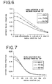
- FIG. 6 is a plot of oxygen mass fraction as a function of radial location, at a penetration distance of 1.0 meters from the lance tip of a preferred lancing system of the invention.
- FIG. 7 is a plot of oxygen mass fraction as a function of radial location, at a penetration distance of 2.0 meters from the lance tip of a preferred lancing system of the invention.
- FIG. 8 is a plot of oxygen mass fraction as a function of radial location, at a penetration distance of 3.0 meters from the lance tip of a preferred lancing system of the invention.
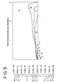
- FIG. 9 is a plot of oxygen mass fraction distribution for the 100/0 case (comparative example) simulation.
- FIG. 10 is a plot of oxygen mass fraction distribution for the 75/25 case simulation of a preferred lancing system of the invention.
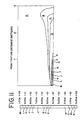
- FIG. 11 is a plot of oxygen mass fraction distribution for the 50/50 case simulation of a preferred lancing system of the invention.
- FIG. 1 Illustrated in FIG. 1, is a preferred system for lancing gas 10 in accordance with the present invention.
- This preferred system includes an inner conduit 20 and an outer conduit 30 .
- Inner conduit 20 and outer conduit 30 are concentric to each other and are in communication with the same or different gas supplies.
- Inner conduit 20 has a distal end 40 and outer conduit has a distal end 50.
- inner conduit 20 has an inner diameter d 1 and outer conduit 30 has an inner diameter d 2 .
- Diameter d 1 preferably ranges from about 1 cm to about 16 cm, and most preferably from about 2 cm to about 10 cm.
- Diameter d 2 preferably ranges from about 2 cm to about 31 cm, and is most preferably from about 5 cm to about 21 cm.
- Distal end 40 is recessed a distance Y from Distal end 50.
- This distance Y preferably ranges from about 0.5 to about 6 times diameter d 2 , or from about 1 cm to about 186 cm, and most preferably from about 1 to about 4 times diameter d 2 , or from about 5 cm to about 84 cm.
- Inner conduit 20 is adapted to transport a first gas G 1 at a first velocity u 1 .
- Outer conduit 30 is adapted to transport a second gas G 2 at a second velocity u 2 .
- First velocity u 1 is greater than second velocity u 2 to thereby create a shielded transition zone that ensures that first gas G 1 has a lower degree of entrainment of dust, particulates, and undesirable gases from the environment while it penetrates deeper into the flame neighborhood.
- the mass flow rate which is the amount of mass transported over time, of first gas G 1 is greater than the mass flow rate of second gas G 2 to create the above-described shielded transition zone.
- the mass flow rate of first gas G 1 is at least two to three times greater than the mass flow rate of second gas G 2 to minimize the above-described entrainment.
- the interaction between first gas G 1 and second gas G 2 after they exit inner conduit 20 and outer conduit 30, respectively, provides a wide lancing jet that preferably interacts more intensely with its target, either the fuel jet or the flame.
- the mass flow rate of first gas G 1 preferably ranges from about 0.1 ton per day ("t/d") to about 200 t/d, and most preferably from about 1 t/d to about 100 t/d.
- the mass flow rate of second gas G 2 preferably ranges from about 0 t/d to about 100 t/d, and most preferably from about 0 t/d to about 50 t/d.
- the supply pressure of first gas G 1 preferably ranges from about 500 Pa to about 700,000 Pa, and most preferably from about 650 Pa to about 450,000 Pa.
- the supply pressure of second gas G 2 preferably ranges from about 70 Pa to about 150,000 Pa, and most preferably from about 150 Pa to about 75,000 Pa.
- First gas G 1 and second gas G 2 can be of the same or different chemical composition.
- first gas G 1 is preferably oxygen-enriched air or, more preferably, oxygen derived from a Pressure Swing Adsorption (PSA), Volume Swing Adsorption (VSA) or Temperature Swing Adsorption (TSA) process, all of which are commonly known in the art.
- PSA Pressure Swing Adsorption
- VSA Volume Swing Adsorption
- TSA Temperature Swing Adsorption
- First gas G 1 will be lanced deep into the kiln.
- Second gas G 2 is preferably low-pressure oxygen which is more preferably derived from a PSA, VSA or TSA process. This design reduces the amount of lanced oxygen needed to maintain the combustion reaction in the kiln, and reduces the pressure necessary to supply the oxygen.
- the second gas G 2 from more preferable to less preferable, include: air, nitrogen, argon, carbon dioxide, flue gas, and steam.
- the oxygen-enriched air, or oxygen may be provided from vaporizing liquid oxygen from a cryogenic Air Separation Unit (ASU), which is commonly known in the art, and the like.
- ASU Air Separation Unit
- substantially pure (about 90%) oxygen from a PSA, VSA or TSA process is preferred.
- first gas G 1 is oxygen and second gas G 2 is nitrogen or argon
- first gas G 1 and second gas G 2 can be supplied by the same or different gas sources.
- a cryogenic ASU can supply oxygen and either nitrogen or argon.
- vaporized liquid oxygen can supply the oxygen while vaporized liquid nitrogen supplies the nitrogen or vaporized argon supplies the argon.
- a PSA, VSA, or TSA process can supply oxygen while a cryogenic ASU supplies the nitrogen.
- a cryogenic ASU typically supplies gases at higher pressures than a PSA, VSA or TSA process, it may be preferable to have a cryogenic ASU supply the oxygen while a PSA, VSA or TSA process supplies the nitrogen.
- FIG. 2 shows that immediately downstream of the jet nozzle 100 is a core zone 110 , where the mass, velocity, and concentration of the lanced gas remain unchanged. This core zone extends to a length of about 4 times the diameter d o of the jet nozzle 100.
- a transition zone 120 Downstream of the core zone 110 is a transition zone 120, where mass, velocity, and concentration of the lanced gas are transferred perpendicular to the direction of flow.
- This transition zone 120 extends to a length of about 8 times the diameter d o of the jet nozzle 100.
- a similarity zone 130 Downstream of the transition zone 120 is a similarity zone 130, where the velocity profiles in all cross-sections perpendicular to the main flow direction can be described by the same function, as can the distributions of concentration and temperature.
- FIG. 3 illustrates the performance of a standard lance.
- FIG. 3 illustrates that the mass M of the lanced gas increases by about 5 times at X/d o is equal to 15, where X is the penetration distance of the lanced gas.
- CFD Computational Fluid Dynamic
- the simulated case includes an inner conduit, with an inside diameter of 0.056 meter and an outside diameter of 0.060 meter, positioned concentrically within an outer conduit having an inside diameter of 0.092 meter.
- the penetration distance of oxygen in the 100/0 case would be the largest.
- the results below show that, using the present invention, the penetration distance of oxygen in the 75/25 and 50/50 cases can surpass that of the 100/0 case.
- FIGS. 4-8 present the oxygen mass fraction variation into the lanced environment, in a radial direction, at different axial locations into the medium.
- FIG. 4 presents the radial variation of the oxygen mass fraction at a penetration distance of 0.3 meters from the lance exit.
- the 50/50 case of the invention leads to the widest oxygen jet, while the 100/0 case (comparative example) leads to the narrowest jet, resulting in undesirable entrainment.
- the 75/25 case of the invention is situated between the two other cases, showing an improvement with respect to the single jet lance.
- the 75/25 case presents an oxygen concentration at a radial location of 0.0 meters that is 26% higher than that of the 100/0 case.
- the 50/50 case has an oxygen concentration at a radial location of 0.0 meters that is 34% higher than that of the 100/0 case.
- the jet width is significantly higher for the two jet cases.
- FIG. 5 illustrates the radial oxygen distribution at a penetration distance of 0.5 meters from the lance exit.
- the 75/25 case presents an oxygen concentration at a radial location of 0.0 meters that is 28% higher than that of the 100/0 case.
- the 50/50 case has an oxygen concentration at a radial location of 0.0 meters that is 41% higher than that of the 100/0 case.
- the jet width is significantly higher for the two jet cases.
- FIG. 6 shows the radial oxygen distribution at a penetration distance of 1.0 meter from the lance exit.
- the 75/25 case presents an oxygen concentration at a radial location of 0.0 meters that is 26% higher than that of the 100/0 case.
- the 50/50 case has an oxygen concentration at a radial location of 0.0 meters that is 53% higher than that of the 100/0 case.
- the jet width is significantly higher for the two jet cases.
- FIG. 7 shows the radial oxygen distribution at a penetration distance of 2.0 meters from the lance exit. While the 75/25 case and the 50/50 case provide a higher oxygen concentration than the 100/0 case at a radial location of 0.0 meters, the oxygen concentrations for all three cases are almost identical starting at a radial location of about 0.18 meters.
- FIG. 8 shows the radial oxygen distribution at a penetration distance of 3.0 meters from the lance exit.
- the results clearly show the advantages of the 72/25 case.
- the oxygen concentration at a radial location of 0.0 meters is 20% higher for the 75/25 case when compared to the 100/0 case, and 25% higher when compared to the 50/50 case.
- the 75/25 case presents a consistently higher oxygen concentration for a wide region into the radial direction.
- the 75/25 case is apparently preferable to both the 100/0 case and 50/50 case at a penetration distance of 3.0 meters from the lance exit.
- FIG. 9 shows the two-dimensional oxygen mass fraction distribution for the 100/0 case, which has a "neck" at a penetration distance of 1 meter.
- FIG. 10 shows the two-dimensional oxygen mass fraction distribution for the 75/25 case.
- the 75/25 case does not have the neck observed in the 100/0 case.
- the 75/25 case provides a longer jet than the 100/0 case. The longer jet is obtained by using a lower inlet velocity, which also allows for a lower inlet pressure. This aspect is presented below in Table 1.
- FIG. 11 shows the two-dimensional oxygen mass fraction distribution for the 50/50 case.
- the 50/50 case grows more continuously than the 100/0 case, resulting in a higher oxygen concentration in the jet.
- the higher oxygen concentration reduces entrainment into the jet and allows for a greater impact on the medium.
- the 50/50 case does not have the neck observed in the 100/0 case, but the jet length is lower than the two other cases. This result can be attributed to the very low inlet velocity in the inner conduit, leading to a somewhat diminished jet penetration.
- the inlet velocity in the 50/50 case is too low to maintain a longer jet.
- the longer jet achieved by the 75/25 case is preferable to the shorter jets achieved by the 100/0 case and the 50/50 case.
- Table 1 shows the average pressure of gas lanced into the combustion environment. The results show that the 100/0 case requires the highest supply pressure due to the high inlet velocity.
- the 75/25 case requires a pressure that is about 50% lower than the 100/0 case.
- the 50/50 case requires a pressure that is about 60% lower than the 100/0 case.
- the lower supply pressures permitted in the 75/25 and 50/50 cases, which use concentric conduit configurations similar to the present invention should result in significant cost savings.
- the combination of the low supply pressure and longer jet provided by the 75/25 case is preferable to the results from the 100/0 case and the 50/50 case.
- a concentric conduit lance with greater mass flow through the inner pipe than the outer pipe is an apparently preferable embodiment.
- the concentric conduit lance of the present invention constitutes a clear advantage over the traditional lancing design of a single conduit. This improvement is evident by the increased penetration distance of the lanced gas, increased width of the lanced gas, and the lower required pressure of the lanced gas. Optimizations can be performed with respect to many variables, including jet penetration distance, width, inlet pressure, choice of lanced gas, temperature, and concentration levels. Important savings in terms of the lanced gas are expected, particularly in combustion applications.
Landscapes
- Engineering & Computer Science (AREA)
- Chemical & Material Sciences (AREA)
- Combustion & Propulsion (AREA)
- Mechanical Engineering (AREA)
- General Engineering & Computer Science (AREA)
- Furnace Charging Or Discharging (AREA)
- Carbon Steel Or Casting Steel Manufacturing (AREA)
- Air Supply (AREA)
Abstract
Description
- This invention relates, in general, to lancing design in industrial applications, and more particularly, to improving the combustion-enhancing characteristics of gases lanced into combustion environments.
- Lancing is a process used to improve combustion in industrial applications. Typically, lancing involves injecting gas into a primary flame or fuel stream so as to maintain flame stability and aid the fuel ignition process. This is especially true for applications such as rotary kilns, where low quality fuels are often used and dust is present in large quantities in the flame neighborhood. Oxygen is commonly used as a lancing gas in these applications.
- Ideally, the exposure of the lanced gas to the primary flame or fuel stream is at a maximum. In order to obtain maximum exposure, the lanced gas must penetrate far into the fuel environment and sweep over the fuel jet over a wide area. Thus, high velocity lances are traditionally employed, which have the disadvantage of often entraining a large volume of the surrounding medium.
- In many combustion applications, the entrainment of flue gases, nitrogen, particulates, and dust can reduce the lanced gas concentration. Thus, it is more difficult to maintain uniform flame temperature profiles and ideal combustion conditions.
- Furthermore, high velocity lances can require high supply pressures and high operating costs. In addition, high velocity lances can create high particulate and NOx emissions, and can increase safety risks, as the high velocities at the lance exit increase the chances of premature ignition.
- Accordingly, there is a need for a lancing process that transports the lanced gas a greater distance and sweeps over the fuel jet over a wide area, while having greater injected gas concentration. Moreover, there is a need for a cost-effective lancing process that does not require high velocities or high supply pressures and that does not pose environmental or safety risks.
- The present invention provides a method and system for lancing a gas into an environment which allows variable amounts of non-lanced gas to be entrained in the lanced gas depending on the ratio of mass flow rates and the ratio of velocities of the lanced gas and the non-lanced gas. In particular, systems are provided which comprise of an inner conduit and an outer conduit, said inner conduit being in communication with a gas supply and adapted to transport a gas at a first mass flow rate, said outer conduit being in communication with a gas supply and adapted to transport a gas at a second mass flow rate, the first mass flow rate being greater than the second mass flow rate.
- In another aspect of the invention, a method is provided for injecting a gas at a first mass flow rate through the inner conduit, and injecting a gas at a second mass flow rate through the outer conduit, the first mass flow rate being greater than the second mass flow rate.
- In yet another aspect of the invention, the distal end of the inner conduit is recessed a distance from the distal end of the outer conduit.
- It is noted that, unless otherwise noted, the pressures given in Pa are intended to refer to gauge pressures.
- These and other features of the invention will become apparent upon review of the following detailed description of the presently preferred embodiments of the invention, taken into conjunction with the appended figures.
- FIG. 1 is a cross-sectional schematic diagram of a lancing system according to a preferred embodiment of the present invention.
- FIG. 2 is a schematic diagram of the core, transition, and similarity zones that a lanced gas typically encounters after exiting the lance tip in a known standard lance, according to turbulent jet theory.
- FIG. 3 is a plot of the distribution of mass, axial velocity, and concentration of lanced gas as a function of normalized distance from the lance tip in a known standard lance, according to turbulent jet theory.
- FIG. 4 is a plot of oxygen mass fraction as a function of radial location, at a penetration distance of 0.3 meters from the lance tip of a preferred lancing system of the invention.
- FIG. 5 is a plot of oxygen mass fraction as a function of radial location, at a penetration distance of 0.5 meters from the lance tip of a preferred lancing system of the invention.
- FIG. 6 is a plot of oxygen mass fraction as a function of radial location, at a penetration distance of 1.0 meters from the lance tip of a preferred lancing system of the invention.
- FIG. 7 is a plot of oxygen mass fraction as a function of radial location, at a penetration distance of 2.0 meters from the lance tip of a preferred lancing system of the invention.
- FIG. 8 is a plot of oxygen mass fraction as a function of radial location, at a penetration distance of 3.0 meters from the lance tip of a preferred lancing system of the invention.
- FIG. 9 is a plot of oxygen mass fraction distribution for the 100/0 case (comparative example) simulation.
- FIG. 10 is a plot of oxygen mass fraction distribution for the 75/25 case simulation of a preferred lancing system of the invention.
- FIG. 11 is a plot of oxygen mass fraction distribution for the 50/50 case simulation of a preferred lancing system of the invention.
- Illustrated in FIG. 1, is a preferred system for
lancing gas 10 in accordance with the present invention. This preferred system includes aninner conduit 20 and anouter conduit 30.Inner conduit 20 andouter conduit 30 are concentric to each other and are in communication with the same or different gas supplies.Inner conduit 20 has adistal end 40 and outer conduit has adistal end 50. In addition,inner conduit 20 has an inner diameter d1 andouter conduit 30 has an inner diameter d2 . Diameter d1 preferably ranges from about 1 cm to about 16 cm, and most preferably from about 2 cm to about 10 cm. Diameter d2 preferably ranges from about 2 cm to about 31 cm, and is most preferably from about 5 cm to about 21 cm. -
Distal end 40 is recessed a distance Y fromDistal end 50. This distance Y preferably ranges from about 0.5 to about 6 times diameter d2 , or from about 1 cm to about 186 cm, and most preferably from about 1 to about 4 times diameter d2 , or from about 5 cm to about 84 cm. -
Inner conduit 20 is adapted to transport a first gas G1 at a first velocity u1 .Outer conduit 30 is adapted to transport a second gas G2 at a second velocity u2 . First velocity u1 is greater than second velocity u2 to thereby create a shielded transition zone that ensures that first gas G1 has a lower degree of entrainment of dust, particulates, and undesirable gases from the environment while it penetrates deeper into the flame neighborhood. Similarly, the mass flow rate, which is the amount of mass transported over time, of first gas G1 is greater than the mass flow rate of second gas G2 to create the above-described shielded transition zone. Preferably, the mass flow rate of first gas G1 is at least two to three times greater than the mass flow rate of second gas G2 to minimize the above-described entrainment. The interaction between first gas G1 and second gas G2 after they exitinner conduit 20 andouter conduit 30, respectively, provides a wide lancing jet that preferably interacts more intensely with its target, either the fuel jet or the flame. - The mass flow rate of first gas G1 preferably ranges from about 0.1 ton per day ("t/d") to about 200 t/d, and most preferably from about 1 t/d to about 100 t/d. The mass flow rate of second gas G2 preferably ranges from about 0 t/d to about 100 t/d, and most preferably from about 0 t/d to about 50 t/d.
- The supply pressure of first gas G1 preferably ranges from about 500 Pa to about 700,000 Pa, and most preferably from about 650 Pa to about 450,000 Pa. The supply pressure of second gas G2 preferably ranges from about 70 Pa to about 150,000 Pa, and most preferably from about 150 Pa to about 75,000 Pa.
- First gas G1 and second gas G2 can be of the same or different chemical composition. In rotary kiln applications, first gas G1 is preferably oxygen-enriched air or, more preferably, oxygen derived from a Pressure Swing Adsorption (PSA), Volume Swing Adsorption (VSA) or Temperature Swing Adsorption (TSA) process, all of which are commonly known in the art. First gas G1 will be lanced deep into the kiln. Second gas G2 is preferably low-pressure oxygen which is more preferably derived from a PSA, VSA or TSA process. This design reduces the amount of lanced oxygen needed to maintain the combustion reaction in the kiln, and reduces the pressure necessary to supply the oxygen. Other possibilities for the second gas G2 , from more preferable to less preferable, include: air, nitrogen, argon, carbon dioxide, flue gas, and steam. It will be appreciated by those skilled in the art that the oxygen-enriched air, or oxygen, may be provided from vaporizing liquid oxygen from a cryogenic Air Separation Unit (ASU), which is commonly known in the art, and the like. The use of substantially pure (about 90%) oxygen from a PSA, VSA or TSA process is preferred.
- When first gas G1 is oxygen and second gas G2 is nitrogen or argon, first gas G1 and second gas G2 can be supplied by the same or different gas sources. For example, a cryogenic ASU can supply oxygen and either nitrogen or argon. Alternatively, vaporized liquid oxygen can supply the oxygen while vaporized liquid nitrogen supplies the nitrogen or vaporized argon supplies the argon. In another embodiment, a PSA, VSA, or TSA process can supply oxygen while a cryogenic ASU supplies the nitrogen. However, because a cryogenic ASU typically supplies gases at higher pressures than a PSA, VSA or TSA process, it may be preferable to have a cryogenic ASU supply the oxygen while a PSA, VSA or TSA process supplies the nitrogen.
- The fundamental characteristics of a turbulent jet, which are well-known in the art, are described by G.N. Abramovich in his Theory of Turbulent Jets (1963), and are shown in FIGS. 2 and 3. FIG. 2 shows that immediately downstream of the
jet nozzle 100 is acore zone 110, where the mass, velocity, and concentration of the lanced gas remain unchanged. This core zone extends to a length of about 4 times the diameter do of thejet nozzle 100. - Downstream of the
core zone 110 is atransition zone 120, where mass, velocity, and concentration of the lanced gas are transferred perpendicular to the direction of flow. Thistransition zone 120 extends to a length of about 8 times the diameter do of thejet nozzle 100. Downstream of thetransition zone 120 is asimilarity zone 130, where the velocity profiles in all cross-sections perpendicular to the main flow direction can be described by the same function, as can the distributions of concentration and temperature. FIG. 3 illustrates the performance of a standard lance. FIG. 3 illustrates that the mass M of the lanced gas increases by about 5 times at X/do is equal to 15, where X is the penetration distance of the lanced gas. This increase in mass M in the axial direction in a standard lance is due to the entrainment of impurities from the surrounding gas, which in this case is air or a combination of air and combustion products. In addition, the velocity U of the lanced gas decreases by about 60% and the concentration C of the lanced gas decreases by about 70% at the same distance. Mo , Uo , and Co are the initial mass, velocity, and concentration of the lanced gas, respectively. Thus, in order to make known, standard lancing processes more effective in industrial applications, penetration distance X has to be increased while minimizing the entrainment of impurities in the lanced gas. - In order to further demonstrate the advantages of the proposed device over conventional lances, the following example has been simulated by Computational Fluid Dynamic (CFD) simulation, which is commonly known in the art. A given amount of oxygen is injected into a combustion environment with both a traditional lance and a system according to the present invention. In order to evaluate the interactions between the lanced gas and the environment, the oxygen is lanced into a medium consisting of nitrogen. The simulation is performed with FLUENT UNS software, which is commonly used in the art and which is available from Fluent, Inc.
- For the present invention, the simulated case includes an inner conduit, with an inside diameter of 0.056 meter and an outside diameter of 0.060 meter, positioned concentrically within an outer conduit having an inside diameter of 0.092 meter. Three cases have been evaluated:
- 1. In a traditional, or single jet, lance, only oxygen is lanced through the inner conduit at a velocity of 277 meters/second ("m/s"). This case is represented as "100/0" in FIGS. 4-9.
- 2. Oxygen is lanced through the inner conduit at a velocity of 200 m/s and through the outer conduit at a velocity of 50 m/s. The inner conduit carries 75% of the oxygen mass flow, and the outer conduit carries the remaining 25% of the oxygen mass flow. This case is represented as "75/25" in FIGS. 4-8, 10.
- 3. Oxygen is lanced through the inner conduit at a velocity of 140 m/s and through the outer conduit at a velocity of 89 m/s. The inner conduit carries 50% of the oxygen mass flow, and the outer conduit carries the other 50% of the oxygen mass flow. This case is represented as "50/50" in FIGS. 4-8, 11.
-
- One would expected that, given the larger velocities of oxygen in the 100/0 case, the penetration distance of oxygen in the 100/0 case would be the largest. However, the results below show that, using the present invention, the penetration distance of oxygen in the 75/25 and 50/50 cases can surpass that of the 100/0 case.
- FIGS. 4-8 present the oxygen mass fraction variation into the lanced environment, in a radial direction, at different axial locations into the medium.
- FIG. 4 presents the radial variation of the oxygen mass fraction at a penetration distance of 0.3 meters from the lance exit. The 50/50 case of the invention leads to the widest oxygen jet, while the 100/0 case (comparative example) leads to the narrowest jet, resulting in undesirable entrainment.
- This suggests that the traditional lancing method of a single jet is lacking in applications where a clean, relatively pure jet is needed. The 75/25 case of the invention is situated between the two other cases, showing an improvement with respect to the single jet lance. In fact, the 75/25 case presents an oxygen concentration at a radial location of 0.0 meters that is 26% higher than that of the 100/0 case. Moreover, the 50/50 case has an oxygen concentration at a radial location of 0.0 meters that is 34% higher than that of the 100/0 case. In addition, the jet width is significantly higher for the two jet cases.
- Similar trends are evident in FIGS. 5-8. FIG. 5 illustrates the radial oxygen distribution at a penetration distance of 0.5 meters from the lance exit. Here, the 75/25 case presents an oxygen concentration at a radial location of 0.0 meters that is 28% higher than that of the 100/0 case. Meanwhile, the 50/50 case has an oxygen concentration at a radial location of 0.0 meters that is 41% higher than that of the 100/0 case. Again, the jet width is significantly higher for the two jet cases.
- FIG. 6 shows the radial oxygen distribution at a penetration distance of 1.0 meter from the lance exit. The 75/25 case presents an oxygen concentration at a radial location of 0.0 meters that is 26% higher than that of the 100/0 case. The 50/50 case has an oxygen concentration at a radial location of 0.0 meters that is 53% higher than that of the 100/0 case. And again, the jet width is significantly higher for the two jet cases.
- FIG. 7 shows the radial oxygen distribution at a penetration distance of 2.0 meters from the lance exit. While the 75/25 case and the 50/50 case provide a higher oxygen concentration than the 100/0 case at a radial location of 0.0 meters, the oxygen concentrations for all three cases are almost identical starting at a radial location of about 0.18 meters.
- FIG. 8 shows the radial oxygen distribution at a penetration distance of 3.0 meters from the lance exit. The results clearly show the advantages of the 72/25 case. The oxygen concentration at a radial location of 0.0 meters is 20% higher for the 75/25 case when compared to the 100/0 case, and 25% higher when compared to the 50/50 case. Furthermore, the 75/25 case presents a consistently higher oxygen concentration for a wide region into the radial direction. Thus, the 75/25 case is apparently preferable to both the 100/0 case and 50/50 case at a penetration distance of 3.0 meters from the lance exit.
- FIG. 9 shows the two-dimensional oxygen mass fraction distribution for the 100/0 case, which has a "neck" at a penetration distance of 1 meter. FIG. 10 shows the two-dimensional oxygen mass fraction distribution for the 75/25 case. The 75/25 case does not have the neck observed in the 100/0 case. In addition, the 75/25 case provides a longer jet than the 100/0 case. The longer jet is obtained by using a lower inlet velocity, which also allows for a lower inlet pressure. This aspect is presented below in Table 1.
- FIG. 11 shows the two-dimensional oxygen mass fraction distribution for the 50/50 case. The 50/50 case grows more continuously than the 100/0 case, resulting in a higher oxygen concentration in the jet. The higher oxygen concentration reduces entrainment into the jet and allows for a greater impact on the medium. The 50/50 case does not have the neck observed in the 100/0 case, but the jet length is lower than the two other cases. This result can be attributed to the very low inlet velocity in the inner conduit, leading to a somewhat diminished jet penetration. Thus, while the lower inlet velocity in the 75/25 case created a longer jet, the inlet velocity in the 50/50 case is too low to maintain a longer jet. The longer jet achieved by the 75/25 case is preferable to the shorter jets achieved by the 100/0 case and the 50/50 case. Table 1 shows the average pressure of gas lanced into the combustion environment. The results show that the 100/0 case requires the highest supply pressure due to the high inlet velocity. The 75/25 case requires a pressure that is about 50% lower than the 100/0 case. The 50/50 case requires a pressure that is about 60% lower than the 100/0 case. Thus, the lower supply pressures permitted in the 75/25 and 50/50 cases, which use concentric conduit configurations similar to the present invention, should result in significant cost savings. Moreover, the combination of the low supply pressure and longer jet provided by the 75/25 case is preferable to the results from the 100/0 case and the 50/50 case. Accordingly, a concentric conduit lance with greater mass flow through the inner pipe than the outer pipe is an apparently preferable embodiment.
Average inlet oxygen pressure (Pa) for the three cases. CASE PRESSURE (Pa) 100/0 2850 75/25 1450 50/50 1190 - The results above show that the concentric conduit lance of the present invention constitutes a clear advantage over the traditional lancing design of a single conduit. This improvement is evident by the increased penetration distance of the lanced gas, increased width of the lanced gas, and the lower required pressure of the lanced gas. Optimizations can be performed with respect to many variables, including jet penetration distance, width, inlet pressure, choice of lanced gas, temperature, and concentration levels. Important savings in terms of the lanced gas are expected, particularly in combustion applications.
- It is intended that the foregoing detailed description be regarded as illustrative rather than limiting and that it be understood that it is the following claims, including all equivalents, which are intended to define the scope of this invention.
Claims (48)
- A system for lancing gas into an environment, comprising:
an inner conduit and an outer conduit, said inner conduit being in communication with a gas supply and adapted to transport a gas at a first mass flow rate, said outer conduit being in communication with a gas supply and adapted to transport a gas at a second mass flow rate, the first mass flow rate being greater than the second mass flow rate. - The system of claim 1 wherein the first mass flow rate is at least two times greater than the second mass flow rate.
- The system of claim 1 wherein the first mass flow rate is at least three times greater than the second mass flow rate.
- The system of claim 1 wherein the first mass flow rate is at least 10 tons per day and the second mass flow rate is at least 5 tons per day.
- The system of claim 1 wherein the first mass flow rate is at least 50 tons per day and the second mass flow rate is at least 25 tons per day.
- The system of claim 1 wherein the first mass flow rate is at least 100 tons per day and the second mass flow rate is at least 50 tons per day.
- The system of claim 1 wherein the first mass flow rate is at least 150 tons per day and the second mass flow rate is at least 75 tons per day.
- The system of claim 1 wherein the distal end of the inner conduit is recessed a distance from the distal end of the outer conduit.
- The system of claim 8 wherein the inner diameter of the distal end of the inner conduit ranges from about 1 to about 16 cm, and the inner diameter of the distal end of the outer conduit ranges from about 2 to about 31 cm.
- The system of claim 8 wherein the inner diameter of the distal end of the inner conduit ranges from about 2 to about 10 cm, and the inner diameter of the distal end of the outer conduit ranges from about 5 to about 21 cm.
- The system of claim 8 wherein the recess distance ranges from about 0.5 to about 6 times the inner diameter of distal end of the outer conduit.
- The system of claim 8 wherein the recess distance ranges from about 1 to about 4 times the inner diameter of distal end of the outer conduit.
- The system of claim 8 wherein the recess distance ranges from about 1 to about 186 cm.
- The system of claim 8 wherein the recess distance ranges from 5 to about 84 cm.
- The system of claim 1 wherein the gas transported though the inner conduit is supplied at a pressure ranging from about 500 Pa to about 700,000 Pa and the gas transported through the outer conduit is supplied at a pressure ranging from about 70 Pa to about 150,000 Pa.
- The system of claim 1 wherein the gas transported through the inner conduit is supplied at a pressure ranging from about 650 Pa to about 450,000 Pa and the gas transported through the outer conduit is supplied at a pressure ranging from about 150 Pa to about 75,000 Pa.
- The system of claim 1 wherein the gas transported through the inner conduit is oxygen and the gas transported through the outer conduit is oxygen.
- The system of claim 1 wherein the gas transported through the inner conduit is oxygen and the gas transported through the outer conduit is air.
- The system of claim 1 wherein the gas transported through the inner conduit is oxygen and the gas transported through the outer conduit is nitrogen.
- The system of claim 1 wherein the gas transported through the inner conduit is oxygen and the gas transported through the outer conduit is carbon dioxide.
- The system of claim 1 wherein the gas transported through the inner conduit is oxygen and the gas transported through the outer conduit is flue gas.
- The system of claim 1 wherein the gas transported through the inner conduit is oxygen and the gas transported through the outer conduit is argon.
- The system of claim 1 wherein the gas transported through the inner conduit is oxygen and the gas transported through the outer conduit is steam.
- The system of claim 1 wherein the gas supply for the gas transported through the inner conduit is the same as the gas supply for the gas transported through the outer conduit.
- The system of claim 1 wherein the gas supply for the gas transported through the inner conduit is different from the gas supply for the gas transported through the outer conduit.
- A method of lancing gas into an environment, comprising the steps of:injecting a gas at a first mass flow rate through an inner conduit; andinjecting a gas at a second mass flow rate through an outer conduit, the inner and outer conduits being concentric, and the first mass flow rate being greater than the second mass flow rate.
- The method of claim 26 wherein the first mass flow rate is at least two times greater than the second mass flow rate.
- The method of claim 26 wherein the first mass flow rate is at least three times greater than the second mass flow rate.
- The method of claim 26 wherein the first mass flow rate is at least 10 tons per day and the second mass flow rate is at least 5 tons per day.
- The method of claim 26 wherein the first mass flow rate is at least 50 tons per day and the second mass flow rate is at least 25 tons per day.
- The method of claim 26 wherein the first mass flow rate is at least 100 tons per day and the second mass flow rate is at least 50 tons per day.
- The method of claim 26 wherein the first mass flow rate is at least 150 tons per day and the second mass flow rate is at least 75 tons per day.
- The method of claim 26 wherein the distal end of the inner conduit is recessed a distance from the distal end of the outer conduit.
- The method of claim 33 wherein the inner diameter of the distal end of the inner conduit ranges from about 1 to about 16 cm, and the inner diameter of the distal end of the outer conduit ranges from about 2 to about 31 cm.
- The method of claim 33 wherein the inner diameter of the distal end of the inner conduit ranges from about 2 to about 10 cm, and the inner diameter of the distal end of the outer conduit ranges from about 5 to about 21 cm.
- The method of claim 33 wherein the recess distance ranges from about 0.5 to about 6 times the inner diameter of distal end of the outer conduit.
- The method of claim 33 wherein the recess distance ranges from about 1 to about 4 times the inner diameter of distal end of the outer conduit.
- The method of claim 33 wherein the recess distance ranges from about 1 to about 186 cm.
- The method of claim 33 wherein the recess distance ranges from 5 to about 84 cm.
- The method of claim 26 wherein the gas transported through the inner conduit is supplied at a pressure ranging from about 500 Pa to about 700,000 Pa and the gas transported through the outer conduit is supplied at a pressure ranging from about 70 Pa to about 150,000 Pa.
- The method of claim 26 wherein the gas transported through the inner conduit is supplied at a pressure ranging from about 650 Pa to about 450,000 Pa and the gas transported through the outer conduit is supplied at a pressure ranging from about 150 Pa to about 75,000 Pa.
- The method of claim 26 wherein the gas transported through the inner conduit is oxygen and the gas transported through the outer conduit is oxygen.
- The method of claim 26 wherein the gas transported through the inner conduit is oxygen and the gas transported through the outer conduit is air.
- The method of claim 26 wherein the gas transported through the inner conduit is oxygen and the gas transported through the outer conduit is nitrogen.
- The method of claim 26 wherein the gas transported through the inner conduit is oxygen and the gas transported through the outer conduit is carbon dioxide.
- The method of claim 26 wherein the gas transported through the inner conduit is oxygen and the gas transported through the outer conduit is flue gas.
- The method of claim 26 wherein the gas transported through the inner conduit is oxygen and the gas transported through the outer conduit is argon.
- The method of claim 26 wherein the gas transported through the inner conduit is oxygen and the gas transported through the outer conduit is steam.
Applications Claiming Priority (2)
| Application Number | Priority Date | Filing Date | Title |
|---|---|---|---|
| US52305000A | 2000-03-10 | 2000-03-10 | |
| US523050 | 2000-03-10 |
Publications (2)
| Publication Number | Publication Date |
|---|---|
| EP1132684A2 true EP1132684A2 (en) | 2001-09-12 |
| EP1132684A3 EP1132684A3 (en) | 2002-05-02 |
Family
ID=24083467
Family Applications (1)
| Application Number | Title | Priority Date | Filing Date |
|---|---|---|---|
| EP01400594A Withdrawn EP1132684A3 (en) | 2000-03-10 | 2001-03-07 | Method and system for lancing gas into an environment with variable entrainment of non-lanced gas |
Country Status (3)
| Country | Link |
|---|---|
| US (2) | US6883721B2 (en) |
| EP (1) | EP1132684A3 (en) |
| JP (1) | JP2001296018A (en) |
Families Citing this family (7)
| Publication number | Priority date | Publication date | Assignee | Title |
|---|---|---|---|---|
| US8469295B2 (en) * | 2002-02-15 | 2013-06-25 | Implant Sciences Corporation | Trace chemical particle release nozzle |
| US20090120338A1 (en) * | 2005-10-28 | 2009-05-14 | L'air Liquide Societe Anonyme Pour L'etude Et L 'exploitation Des Procedes Georges Claude | Process and Apparatus for Low-NOx Combustion |
| US7581948B2 (en) * | 2005-12-21 | 2009-09-01 | Johns Manville | Burner apparatus and methods for making inorganic fibers |
| US7802452B2 (en) | 2005-12-21 | 2010-09-28 | Johns Manville | Processes for making inorganic fibers |
| FR2914986B1 (en) * | 2007-04-12 | 2015-04-10 | Saint Gobain Isover | INTERNAL COMBUSTION BURNER |
| US8578965B2 (en) * | 2010-08-17 | 2013-11-12 | Babcock & Wilcox Canada Ltd. | Device and method for supplying a sorbent |
| CN111274708B (en) * | 2020-02-14 | 2022-04-29 | 哈尔滨工程大学 | Method for predicting penetration distance of multiple-injection spraying of marine diesel engine |
Citations (1)
| Publication number | Priority date | Publication date | Assignee | Title |
|---|---|---|---|---|
| FR2797738A1 (en) | 1999-08-18 | 2001-02-23 | Air Liquide | Electric arc furnace supersonic gas injection process, especially for oxygen injection into a steel-making arc furnace, uses a surrounding gas jet to protect the supersonic gas jet against the ambient atmosphere |
Family Cites Families (22)
| Publication number | Priority date | Publication date | Assignee | Title |
|---|---|---|---|---|
| US1030824A (en) * | 1911-04-15 | 1912-06-25 | Edward L Adreon Jr | Burner. |
| US1279315A (en) * | 1918-03-06 | 1918-09-17 | John Foerst | Hydrocarbon-burner. |
| US2478557A (en) * | 1947-09-13 | 1949-08-09 | Walter H Bell | Sprayer and sprayer head for fluent coating materials |
| US2598787A (en) * | 1948-07-10 | 1952-06-03 | Werner H Haak | Torch with concentric gas, oxygen, and mixture outlets |
| GB1021855A (en) * | 1963-01-26 | 1966-03-09 | British Oxygen Co Ltd | Improvements in or relating to the treatment of molten metal |
| US3470061A (en) | 1967-03-03 | 1969-09-30 | Union Camp Corp | Sodium polysulfide pulping process and regeneration |
| US4024229A (en) | 1970-11-06 | 1977-05-17 | The Mead Corporation | Production of polysulfide with PTFE coated catalyst |
| US3860479A (en) | 1971-06-18 | 1975-01-14 | Union Camp Corp | Catalytic oxidation of alkaline pulping liquor |
| JPS5294641A (en) * | 1976-02-03 | 1977-08-09 | Asahi Kogyosha | Air conditioning system using jet consisting of main and auxiliary jets |
| DE2916635C3 (en) * | 1979-04-25 | 1982-08-26 | Messer Griesheim Gmbh, 6000 Frankfurt | Burner head of a fuel-oxygen burner |
| US4515553A (en) * | 1980-04-10 | 1985-05-07 | Kobe Steel, Ltd. | Combustion method for reducing the emission of nitrogen oxides |
| JPS62247812A (en) | 1986-04-18 | 1987-10-28 | Chiyoda Chem Eng & Constr Co Ltd | Pressure-type upward flow deep bed filtration method and filter used in said method |
| FI901050A7 (en) * | 1987-09-02 | 1990-03-01 | Aga Ab | Method for creating an oxidizing flame, use of a burner and burner |
| JPH01234513A (en) * | 1988-03-15 | 1989-09-19 | Sumitomo Metal Ind Ltd | Method for blowing oxygen |
| US5082526A (en) | 1989-01-23 | 1992-01-21 | Pulp And Paper Research Institute Of Canada | Process of producing kraft pulping liquor by the oxidation of white liquor in the presence of lime mud |
| US5209656A (en) * | 1991-08-29 | 1993-05-11 | Praxair Technology, Inc. | Combustion system for high velocity gas injection |
| SE9302213L (en) | 1993-06-28 | 1994-12-05 | Eka Nobel Ab | Preparation of polysulfide by electrolysis of white liquor containing sulfide |
| JPH07216430A (en) * | 1994-02-02 | 1995-08-15 | Nippon Steel Corp | Top blowing lance for molten steel manufacturing and refining molten metal |
| FR2737138B1 (en) * | 1995-07-28 | 1997-08-22 | Air Liquide | METHOD AND DEVICE FOR SPRAYING A LIQUID PRODUCT |
| AU2607297A (en) | 1996-05-03 | 1997-11-26 | Quantum Technologies, Inc. | Method and apparatus for making polysulfides by oxidizing sulfides |
| US5823762A (en) * | 1997-03-18 | 1998-10-20 | Praxair Technology, Inc. | Coherent gas jet |
| US5931654A (en) * | 1997-06-30 | 1999-08-03 | Praxair Technology, Inc. | Recessed furnace lance purge gas system |
-
2001
- 2001-03-07 EP EP01400594A patent/EP1132684A3/en not_active Withdrawn
- 2001-03-12 JP JP2001069033A patent/JP2001296018A/en active Pending
-
2002
- 2002-12-19 US US10/323,541 patent/US6883721B2/en not_active Expired - Lifetime
-
2005
- 2005-04-13 US US11/105,072 patent/US20050230500A1/en not_active Abandoned
Patent Citations (1)
| Publication number | Priority date | Publication date | Assignee | Title |
|---|---|---|---|---|
| FR2797738A1 (en) | 1999-08-18 | 2001-02-23 | Air Liquide | Electric arc furnace supersonic gas injection process, especially for oxygen injection into a steel-making arc furnace, uses a surrounding gas jet to protect the supersonic gas jet against the ambient atmosphere |
Also Published As
| Publication number | Publication date |
|---|---|
| US20050230500A1 (en) | 2005-10-20 |
| US6883721B2 (en) | 2005-04-26 |
| JP2001296018A (en) | 2001-10-26 |
| US20030230644A1 (en) | 2003-12-18 |
| EP1132684A3 (en) | 2002-05-02 |
Similar Documents
| Publication | Publication Date | Title |
|---|---|---|
| KR100538518B1 (en) | FUEL DILUTION METHODS AND APPARATUS FOR NOx REDUCTION | |
| CA2151540C (en) | Staged combustion for reducing nitrogen oxides | |
| KR100394428B1 (en) | FUEL DILUTION METHODS AND APPARATUS FOR NOx REDUCTION | |
| EP0687858A1 (en) | Narrow spray angle liquid fuel atomizers for combustion | |
| EP0601274A1 (en) | Hybrid oxidant combustion method | |
| JP2942711B2 (en) | Deep stage combustion method | |
| EP0731327A1 (en) | Oxidant lancing nozzle | |
| AU2003204347B2 (en) | Coherent jet system with single ring flame envelope | |
| US6883721B2 (en) | Method and system for lancing gas into an environment with variable entrainment of non-lanced gas | |
| EP0889286A1 (en) | Recessed furnace lance purge gas system | |
| US5545033A (en) | Asymmetric oxygen/fuel burner | |
| EP1192979B1 (en) | Reagent delivery process | |
| US7591876B2 (en) | Injection of solids into liquids by means of a shrouded supersonic gas jet | |
| US6773484B2 (en) | Extensionless coherent jet system with aligned flame envelope ports | |
| US6875398B2 (en) | Coherent jet system with outwardly angled flame envelope ports | |
| JP5074395B2 (en) | Method for baking materials with low NOx emissions | |
| US6481998B2 (en) | High velocity reburn fuel injector | |
| JP6741692B2 (en) | Sonic injection furnace | |
| US20200386403A1 (en) | Fluid injection element for a furnace or a burner of a furnace and method for operating a furnace |
Legal Events
| Date | Code | Title | Description |
|---|---|---|---|
| PUAI | Public reference made under article 153(3) epc to a published international application that has entered the european phase |
Free format text: ORIGINAL CODE: 0009012 |
|
| AK | Designated contracting states |
Kind code of ref document: A2 Designated state(s): AT BE CH CY DE DK ES FI FR GB GR IE IT LI LU MC NL PT SE TR |
|
| AX | Request for extension of the european patent |
Free format text: AL;LT;LV;MK;RO;SI |
|
| PUAL | Search report despatched |
Free format text: ORIGINAL CODE: 0009013 |
|
| RAP1 | Party data changed (applicant data changed or rights of an application transferred) |
Owner name: L'AIR LIQUIDE, S.A. A DIRECTOIRE ET CONSEIL DE SUR |
|
| AK | Designated contracting states |
Kind code of ref document: A3 Designated state(s): AT BE CH CY DE DK ES FI FR GB GR IE IT LI LU MC NL PT SE TR |
|
| AX | Request for extension of the european patent |
Free format text: AL;LT;LV;MK;RO;SI |
|
| RIC1 | Information provided on ipc code assigned before grant |
Free format text: 7F 23C 9/00 A, 7F 23L 7/00 B, 7F 23C 7/02 B |
|
| 17P | Request for examination filed |
Effective date: 20021104 |
|
| AKX | Designation fees paid |
Free format text: AT BE CH CY DE DK ES FI FR GB GR IE IT LI LU MC NL PT SE TR |
|
| 17Q | First examination report despatched |
Effective date: 20030113 |
|
| RAP1 | Party data changed (applicant data changed or rights of an application transferred) |
Owner name: L'AIR LIQUIDE, SOCIETE ANONYME POUR L'ETUDE ET L'E |
|
| RAP1 | Party data changed (applicant data changed or rights of an application transferred) |
Owner name: L'AIR LIQUIDE, SOCIETE ANONYME POUR L'ETUDE ET L'E |
|
| STAA | Information on the status of an ep patent application or granted ep patent |
Free format text: STATUS: THE APPLICATION IS DEEMED TO BE WITHDRAWN |
|
| 18D | Application deemed to be withdrawn |
Effective date: 20180515 |
|
| RIC1 | Information provided on ipc code assigned before grant |
Ipc: F23C 9/00 20060101AFI20010619BHEP Ipc: F23L 7/00 20060101ALI20020313BHEP Ipc: F23C 7/02 20060101ALI20020313BHEP |