EP1132678A1 - Leuchte mit einem um einen Mittelpunkt symmetrisch angeordneten Hohllichtleiter und symmetrischer Lichteinstrahlung, insbesondere Rundleuchte - Google Patents
Leuchte mit einem um einen Mittelpunkt symmetrisch angeordneten Hohllichtleiter und symmetrischer Lichteinstrahlung, insbesondere Rundleuchte Download PDFInfo
- Publication number
- EP1132678A1 EP1132678A1 EP01105863A EP01105863A EP1132678A1 EP 1132678 A1 EP1132678 A1 EP 1132678A1 EP 01105863 A EP01105863 A EP 01105863A EP 01105863 A EP01105863 A EP 01105863A EP 1132678 A1 EP1132678 A1 EP 1132678A1
- Authority
- EP
- European Patent Office
- Prior art keywords
- light
- cavity
- lamp
- structural elements
- lines
- Prior art date
- Legal status (The legal status is an assumption and is not a legal conclusion. Google has not performed a legal analysis and makes no representation as to the accuracy of the status listed.)
- Granted
Links
Images


Classifications
-
- G—PHYSICS
- G02—OPTICS
- G02B—OPTICAL ELEMENTS, SYSTEMS OR APPARATUS
- G02B6/00—Light guides; Structural details of arrangements comprising light guides and other optical elements, e.g. couplings
- G02B6/0001—Light guides; Structural details of arrangements comprising light guides and other optical elements, e.g. couplings specially adapted for lighting devices or systems
- G02B6/0011—Light guides; Structural details of arrangements comprising light guides and other optical elements, e.g. couplings specially adapted for lighting devices or systems the light guides being planar or of plate-like form
- G02B6/0033—Means for improving the coupling-out of light from the light guide
- G02B6/0035—Means for improving the coupling-out of light from the light guide provided on the surface of the light guide or in the bulk of it
- G02B6/0045—Means for improving the coupling-out of light from the light guide provided on the surface of the light guide or in the bulk of it by shaping at least a portion of the light guide
- G02B6/0046—Tapered light guide, e.g. wedge-shaped light guide
-
- F—MECHANICAL ENGINEERING; LIGHTING; HEATING; WEAPONS; BLASTING
- F21—LIGHTING
- F21S—NON-PORTABLE LIGHTING DEVICES; SYSTEMS THEREOF; VEHICLE LIGHTING DEVICES SPECIALLY ADAPTED FOR VEHICLE EXTERIORS
- F21S8/00—Lighting devices intended for fixed installation
- F21S8/02—Lighting devices intended for fixed installation of recess-mounted type, e.g. downlighters
-
- F—MECHANICAL ENGINEERING; LIGHTING; HEATING; WEAPONS; BLASTING
- F21—LIGHTING
- F21V—FUNCTIONAL FEATURES OR DETAILS OF LIGHTING DEVICES OR SYSTEMS THEREOF; STRUCTURAL COMBINATIONS OF LIGHTING DEVICES WITH OTHER ARTICLES, NOT OTHERWISE PROVIDED FOR
- F21V5/00—Refractors for light sources
- F21V5/02—Refractors for light sources of prismatic shape
-
- G—PHYSICS
- G02—OPTICS
- G02B—OPTICAL ELEMENTS, SYSTEMS OR APPARATUS
- G02B6/00—Light guides; Structural details of arrangements comprising light guides and other optical elements, e.g. couplings
- G02B6/0001—Light guides; Structural details of arrangements comprising light guides and other optical elements, e.g. couplings specially adapted for lighting devices or systems
- G02B6/0011—Light guides; Structural details of arrangements comprising light guides and other optical elements, e.g. couplings specially adapted for lighting devices or systems the light guides being planar or of plate-like form
- G02B6/0033—Means for improving the coupling-out of light from the light guide
- G02B6/005—Means for improving the coupling-out of light from the light guide provided by one optical element, or plurality thereof, placed on the light output side of the light guide
- G02B6/0053—Prismatic sheet or layer; Brightness enhancement element, sheet or layer
-
- G—PHYSICS
- G02—OPTICS
- G02B—OPTICAL ELEMENTS, SYSTEMS OR APPARATUS
- G02B6/00—Light guides; Structural details of arrangements comprising light guides and other optical elements, e.g. couplings
- G02B6/0001—Light guides; Structural details of arrangements comprising light guides and other optical elements, e.g. couplings specially adapted for lighting devices or systems
- G02B6/0011—Light guides; Structural details of arrangements comprising light guides and other optical elements, e.g. couplings specially adapted for lighting devices or systems the light guides being planar or of plate-like form
- G02B6/0075—Arrangements of multiple light guides
- G02B6/0078—Side-by-side arrangements, e.g. for large area displays
-
- G—PHYSICS
- G02—OPTICS
- G02B—OPTICAL ELEMENTS, SYSTEMS OR APPARATUS
- G02B6/00—Light guides; Structural details of arrangements comprising light guides and other optical elements, e.g. couplings
- G02B6/0001—Light guides; Structural details of arrangements comprising light guides and other optical elements, e.g. couplings specially adapted for lighting devices or systems
- G02B6/0096—Light guides; Structural details of arrangements comprising light guides and other optical elements, e.g. couplings specially adapted for lighting devices or systems the lights guides being of the hollow type
-
- F—MECHANICAL ENGINEERING; LIGHTING; HEATING; WEAPONS; BLASTING
- F21—LIGHTING
- F21W—INDEXING SCHEME ASSOCIATED WITH SUBCLASSES F21K, F21L, F21S and F21V, RELATING TO USES OR APPLICATIONS OF LIGHTING DEVICES OR SYSTEMS
- F21W2131/00—Use or application of lighting devices or systems not provided for in codes F21W2102/00-F21W2121/00
- F21W2131/40—Lighting for industrial, commercial, recreational or military use
- F21W2131/402—Lighting for industrial, commercial, recreational or military use for working places
-
- F—MECHANICAL ENGINEERING; LIGHTING; HEATING; WEAPONS; BLASTING
- F21—LIGHTING
- F21Y—INDEXING SCHEME ASSOCIATED WITH SUBCLASSES F21K, F21L, F21S and F21V, RELATING TO THE FORM OR THE KIND OF THE LIGHT SOURCES OR OF THE COLOUR OF THE LIGHT EMITTED
- F21Y2103/00—Elongate light sources, e.g. fluorescent tubes
- F21Y2103/30—Elongate light sources, e.g. fluorescent tubes curved
- F21Y2103/33—Elongate light sources, e.g. fluorescent tubes curved annular
-
- F—MECHANICAL ENGINEERING; LIGHTING; HEATING; WEAPONS; BLASTING
- F21—LIGHTING
- F21Y—INDEXING SCHEME ASSOCIATED WITH SUBCLASSES F21K, F21L, F21S and F21V, RELATING TO THE FORM OR THE KIND OF THE LIGHT SOURCES OR OF THE COLOUR OF THE LIGHT EMITTED
- F21Y2113/00—Combination of light sources
-
- G—PHYSICS
- G02—OPTICS
- G02B—OPTICAL ELEMENTS, SYSTEMS OR APPARATUS
- G02B6/00—Light guides; Structural details of arrangements comprising light guides and other optical elements, e.g. couplings
- G02B6/0001—Light guides; Structural details of arrangements comprising light guides and other optical elements, e.g. couplings specially adapted for lighting devices or systems
- G02B6/0011—Light guides; Structural details of arrangements comprising light guides and other optical elements, e.g. couplings specially adapted for lighting devices or systems the light guides being planar or of plate-like form
- G02B6/0081—Mechanical or electrical aspects of the light guide and light source in the lighting device peculiar to the adaptation to planar light guides, e.g. concerning packaging
Definitions
- the invention relates to a lamp according to the preamble of claim 1.
- Luminaires for interiors are often subject to the requirement of shielding the radiated Light in several levels, i.e. a decrease in the average luminance of the Light exit surface below a predetermined limit above a limit angle a perpendicular to the light exit surface. It was in the European patent application 99 110 141.1 proposed such a shield in a luminaire with a light pipe, from the light is coupled out to the light exit surface by two plates to bring about with linear prisms whose direction is perpendicular to each other.
- a luminaire for lighting interiors with a non-square housing and / or a non-square light exit surface in particular a circular lamp or a downlight, which has at least one light pipe with a Cavity and a light irradiation device, which comprises one or more light sources and from which light is radiated into the cavity of the light guide, and at least has a light decoupling device which exits light from the cavity decouples on a non-square light exit surface of the lamp, the light decoupling device consists of a translucent material and an interface between two media with different refractive index, that with a refractive Structure of linear refractive structure elements are provided, the light refractive structure at least in a surface perpendicular to the light exit surface the luminaire and the lines followed by the refractive structure elements Coupling of light above a critical angle to a perpendicular to the light exit surface essentially prevented and thereby a shield, based on this area or surfaces generated, characterized in that the light irradi
- exactly one light-refracting structure producing a shield is arranged in the beam path of the light emerging from the light exit surface.
- the lines which the structural elements follow are closed lines, which preferably have symmetry with respect to an axis perpendicular to the interface.
- This symmetry can be discrete or continuous.
- the lines follow one equilateral polygon, e.g. an equilateral triangle, pentagon, hexagon or the like, in in the second case, the lines follow a circle.
- the refractive structure elements correspond to a symmetry with respect to an axis perpendicular to the interface with the refractive structure run and a light irradiation device is arranged along this axis of symmetry, which the light predominantly or essentially in a direction perpendicular to the Lines defining structural elements radiate into the cavity.
- the structural elements are designed in the form of concentric circles are and the light irradiation device is arranged along the axis of symmetry and the light radiates essentially or predominantly radially into the cavity.
- one light source or several light sources along the axis of symmetry are arranged, which light essentially or predominantly in radial Direction radiates into the cavity.
- the light source can be in the cavity of the light guide or outside of the cavity in a central hole in the middle of an annular hollow light guide.
- the light-generating element of the light source should have the smallest possible radial extension have and have a symmetry corresponding to the symmetry of the lines, that is for example a rotational symmetry in the case of circular lines.
- the ideal case would be one point or line light source, in the latter case the line representing the light source specifies with the axis of symmetry coincides.
- you become light sources use that come as close as possible to this ideal, e.g. rod-shaped light sources, halogen bulbs, High-pressure lamps with clear bulbs or light-emitting diodes with small dimensions.
- a rod or the like With light-emitting diodes or others Light sources are occupied with a very small expansion, which light, possibly in interaction with other elements, essentially only in one direction, the LEDs are arranged symmetrically according to the symmetry of the lines.
- a light source has a focusing element, such as a lens or a mirror which essentially emits the light emitted by the light source focused on the axis of symmetry, and a deflection device are assigned, which the focused light from the light source in directions perpendicular to the lines of the Structural elements redirected.
- a focusing element such as a lens or a mirror which essentially emits the light emitted by the light source focused on the axis of symmetry
- a deflection device are assigned, which the focused light from the light source in directions perpendicular to the lines of the Structural elements redirected.
- both functions, the focusing and the deflection, can also be performed by an optical element, e.g. a suitably trained optical body attached to its The light entrance surface has a focusing effect and the light running through it through total reflection redirected, perceived at the same time.
- an optical element e.g. a suitably trained optical body attached to its The light entrance surface has a focusing effect and the light running through it through total reflection redirected, perceived at the same time.
- one or more light sources outside the light guide are arranged along a radially inner or outer edge and the light source one or more collimating elements are assigned, which are those that are radiated into the cavity Light essentially on planes perpendicular to the lines of the refractive Concentrate structural elements.
- a coupling reflector assigned to the light source can be used be provided with a collimating structure.
- a coupling reflector, the one with an elongated lamp, e.g. a rod-shaped lamp or one Ring lamp, cooperating, which extends substantially in the circumferential direction in the Circumferential direction can be formed with concave depressions, each local collecting mirror form.
- Focal point of these local mirrors is that which is reflected by the coupling reflector
- Light of the lamp is concentrated in the direction perpendicular to the circumferential direction.
- a light can be emitted directly from the lamp into the hollow light guide or an aperture can be provided.
- the radiation radiated into the cavity is collimated
- Light slats are provided which essentially direct the light incident on the direction Limit perpendicular to the lines of the prisms.
- a plurality of essentially point-shaped light sources are along of the inner and / or outer edge of the light guide are arranged, the light in the cavity is irradiated.
- each of these light sources can have an individual collimating element, e.g. a reflector, a lens or an aperture can be assigned, which the light of this Light source essentially in the direction perpendicular to the lines of the refractive Structural elements steers.
- an individual collimating element e.g. a reflector, a lens or an aperture can be assigned, which the light of this Light source essentially in the direction perpendicular to the lines of the refractive Structural elements steers.
- a reflector can be a small lamp, e.g. a halogen incandescent lamp and essentially reflect light rays in parallel.
- the lamp can also be a converging lens be connected downstream or an aperture can be connected downstream of the light source, which essentially only lets light through in the radial direction. It can also be provided be that several such lamps assigned a common collimating element is.
- the light from the light source or light sources predominantly or essentially in a radially outer area on the refractive structure comes up with.
- a cover can be provided below the light source, which the direct light from the light source onto the refractive structure near the Center prevented. Because the light from a real light source never radiates completely radially would be in this area, in which the direction of the prism structures is very short Distances changes, part of the light in a non-perpendicular direction to the lines of the refractive structural elements, in which these have no or only a minor one Have a shielding effect. This is prevented by said cover.
- This cover can on the side facing the lamp, possibly also on the refractive side Structure-facing side be designed reflective, so that it from the Lamp incident light to the reflective walls of the light pipe and from there the light decoupling device is reflected. If the light source is on a radial inner or outer edge is arranged, for example, by a suitable design of the coupling reflector and / or the reflective roof wall of the light pipe be that the majority of the light in a radially outer area on the refractive Structure comes up.
- the area of the refractive is Structures in which the direction of the lines changes relatively little, larger.
- the rays of a directed beam with a certain extent therefore have if they hit the structural elements at the outer edge, across the entire width of the Beam only a small deviation from the desired 90 ° to the line direction on, while the deviation will be larger as it approaches the center of symmetry the interface with the refractive structure is incident.
- the invention can provide that the light pipe has the shape of a polygon, with one or more, preferably all sides of this polygon, a light source for coupling light is arranged, which is preferably parallel to the sides of the polygon extends or several point light sources are arranged along the sides.
- the invention relates in particular, but not exclusively, to those lights which of Luminaires are different, which are described in German patent application 199 63 685.0 are, in particular those lights that differ from lights with at least one light guide are in the light from one or more lamps via one or more light coupling sides is coupled and the at least one of the light coupling sides has different light output side with a light output surface, via which light is coupled out, a structure being provided at least on one light outcoupling side which shields the light emerging via this light decoupling side, which is characterized in that the structure consists of light-transmitting elements exists or has this, each with respect to a line parallel to the light decoupling surface are translation invariant, such that they have a constant cross section along this line have, these elements in the direction perpendicular to this line in cross section have a width which, in relation to a direction perpendicular to the light output side, from the side facing the light guide to the side facing away from the light guide Side increases.
- the invention therefore also relates in particular to such lights where the light is not coupled in from one side or where the cross section of the Light-transmitting elements, related to a direction perpendicular to the light output side, from the side facing the light guide to the side facing away from the light guide Side does not increase.
- the housing and / or the light exit surface can in particular be round, elliptical or polygonal his. Also a lamp with a triangular housing and / or a triangular one Light exit surface are possible.
- the invention can provide that a reflecting, wall which delimits the cavity is provided, the distance from the light decoupling device, starting from the point of light coupling from a light source, at least over a section, e.g. in the radial direction, decreases,
- the light from the lamp is at least partially radiated directly into the cavity, so that the mentioned distance in the direction away from the lamp is reduced.
- the said wall of the hollow light guide opposite the light decoupling device is in accordance with one embodiment of the invention, the roof wall of the light guide or the cavity, in which case the height of the cavity from the point of light coupling in radial direction decreases.
- the invention can provide that the linear refractive structure elements of the light-refractive structure have side walls substantially parallel to the line direction, which form an angle at the free end of the structural elements which is greater than 90 °, preferably in a range from 90 ° to 130 ° and in particular according to one Embodiment of the invention can be in a range of 110 ° to 128 °.
- the previous one specified angle ranges from 90 ° to 130 ° or 110 ° to 128 ° are especially for a refractive index of approximately 1.49 is preferred, but can also be used with materials another refractive index that is not too different from 1.49 is. This applies to common materials such as polycarbonate or polyester.
- the preferred angle ranges are different be, whereby these preferred angular ranges for these refractive indices are determined leave the same shielding angles for a given limit of Luminance can be achieved as in the angular range from 90 ° to 130 ° or 110 ° to 128 ° with a refractive index of 1.49.
- this angle may be greater than 90 ° regardless of the refractive index.
- This angle is preferably the same for all structural elements, and all of the rest as well can have the same cross-sectional shape and possibly also identical dimensions.
- the line along which the structural element extends compliant and preferably parallel to the circumferential line, e.g. circular at one circular light exit surface, hexagonal with a hexagonal light exit surface etc.
- the limit value of the luminance can be 200 cd / m 2 , 500 cd / m 2 or 1000 cd / m 2 in accordance with applicable standards or proposed standards.
- the shielding angle is in common applications in the range of more than 45 °, preferably in a range from 50 ° to 75 °, in particular 50 ° to 65 °.
- the light refractive elements have according to the preferred embodiment of the invention along the line direction a constant cross section, which in particular the shape of a Triangle can assume.
- the side walls of the elements do not have to be straight but can also be curved.
- connect the side walls directly to each other at the free end of the structural elements can also be provided that the free end of the structural elements is flattened and the side walls are connected by a flat or curved surface.
- Side surfaces or side surfaces with a flat section at the free end is the then the aforementioned angle through the imaginary extension of the flat side walls or the flat portions of the side walls.
- the aforementioned angle may correspond to the angle of a triangle, the cross-section of the refractive elements is optimal, i.e. with as little as possible Area deviation between the area of the triangle and the cross-sectional area of the refractive Elements, is inscribed.
- a convex i.e. outward curved Sidewall would be this angle by the intersection of two tangents formed, which are applied to the side lines of the cross section of the refractive element, while in the case of a concave, i.e. inward curved side wall, this angle would be determined by two straight lines, each through the head point and the foot point a side line of the cross section, i.e. one corresponding to the side wall in cross section Line, are laid.
- Similar optical properties can also be achieved if only the part of the cross-section is constant at the free end of the prisms along the line direction and, for which above embodiment, an angle constant over the line at the free end Are defined.
- the basic shape of the cross-section can be retained. For example in the case of a triangular cross section with the same basic shape, the height of the triangle change along the line.
- the figure that the Cross-section represents, along the line to a partial figure, for example from one Pentagon into a triangle, which corresponds to the area at the top of the pentagon.
- the refractive elements are made from a body that is moved by moving a cross-sectional area, for example one Triangle, along a leading curve.
- this leading curve can be closed in itself so that it forms a circle, an ellipse Forms polygon or the like.
- the refractive elements then form accordingly at the interface circles, polygons, ellipses or the like.
- the said guide curve conform to the circumferential line of the light exit surface, e.g. a circular line be when the light exit surface is in a circle, etc.
- At least one structure is included circular refractive structural elements.
- the refractive structures can e.g. by making a plate or foil made of a common translucent material, such as glass, polyester, polystyrene, polycarbonate, PET or polymethyl methacrylate, processed or shaped accordingly on a surface becomes.
- a film containing the light-refractive structure can also be placed on a such plate glued or used without a carrier plate.
- the refractive The structure of the plate can point towards or from the cavity of the light guide point away.
- the plate is attached to the housing of the lamp in a conventional manner by suitable means held.
- the hollow light guide of the lamp forms a box open at the bottom, which is closed by the said plate on its underside becomes.
- the lamp is set up so that the light from one or several light sources is coupled from the radial outside of the cavity.
- the radially outer side of the light pipe is preferably open.
- the light guide from Surrounding the outside according to an embodiment of the invention a ring lamp is arranged, which radiates light radially from the outside into the cavity of the light pipe.
- a ring lamp can also have several over the circumference of the light guide distributed light sources can be provided.
- too Light-emitting diodes, photoluminescent foils or the like can be used as the light source.
- the light guide has a radially inner one Has edge and one or more light sources arranged along the radially inner edge are whose light is coupled into the light pipe.
- the invention can also provide that on an inner radial edge of a first light guide then a second, preferably concentric, hollow light guide is provided with one or more light sources between the inner radial edge of the first Hollow light guide and the outer radial edge of the second light guide are arranged.
- a light source extends through an opening in a wall of the light pipe, in particular through an opening in the roof wall, into the cavity of the Extending the light pipe.
- the lights according to the invention can be in various forms, for example as downlights, Pendant light, recessed or surface-mounted light can be realized.
- Fig. 1 is an embodiment of a lamp according to the invention in the schematic Shown as a downlight.
- This downlight has an essentially circular cylindrical shape Housing 1 and a light exit surface arranged concentrically to this housing 3.
- This light exit surface 3 is at the same time the light decoupling surface Hollow light guide 10, which is arranged in the housing 1 and in accordance with a cross section the line II-II of Fig. 1 in Fig. 2 is shown schematically.
- the hollow light guide 10 has a cavity 12 which is from a conical roof wall 14, which has flat wall sections 14a and 14b inclined in a radial cross section, and a light decoupling device 16, which consists of a prism plate 20.
- the cavity 12 is open on the radially outer side. In this opening is a bezel ring 13 used, the function of which will be explained below.
- On this open page is via a ring lamp 22 and a coupling reflector assigned to the ring lamp 22 24 coupled through the aperture ring 13 light into the cavity 12.
- the roof wall 14 is formed reflective and reflects light incident on them to the light decoupling device 16.
- the plate 20 a Some of the light from the lamp 22 or the coupling reflector 24 is directly apparent the plate 20 a. Part of this light passes through the plate 20 and on the light exit surface 3 out. Another part of this light is reflected on the plate 20. The The roof wall 14 reflects this directly on the lamp 22 or the coupling reflector 24 incident light and the light reflected back from the plate 20 down to the Prism plate 20.
- the degree of light decoupling on the prism plate 20 depends, among other things, on the angle of incidence of the incident light rays. It has been shown that there is a more uniform Luminous intensity distribution curve of the lamp can be reached when the reflective roof wall is inclined to the light decoupling device and the distance between the light decoupling device and the roof wall is reduced towards away from the lamp. In particular the light intensity distribution curve in the range of 0 ° is thereby evened out and on Avoided or reduced the minimum light intensity distribution in this area. It has it has also been shown that such a design improves the lighting efficiency leads. For this reason, the roof wall 14 is conical and has in radial cross section two straight, inclined sections 14a and 14b, so that the height of the cavity 12 is smallest in the middle and at the radially outer edge greatest is.
- the prismatic plate 20 is provided with a structure which essentially prevents coupling out of light above a critical angle to the normal to the light exit surface in certain planes and thereby shields, ie a lowering of the mean luminance of the light exit surface below a limit value, for example 200 cd / m 2 , 500 cd / m 2 or 1000 cd / m 2 .
- the prism plate 20 has a structure on its side facing away from the cavity 12 of circular prisms 30 (see FIG. 1), which are triangular in a radial cross section Have shape, as can be seen from Fig. 3.
- Fig. 3 shows that the prisms directly adjoin each other, evenly spaced ridges 32a, 32b, ... (hereinafter collectively referred to as 32) and by evenly spaced apart Wells 34a, 34b, ... hereinafter collectively designated 34, from each other are separated.
- the depressions 34 and the ridges 32 form on the cavity 12 opposite side of the plate 20 circular concentric lines, which is schematic in Fig. 1 are shown.
- the shield can e.g. generated by total reflection in the prisms.
- Light in the Prisms become an optically thinner medium, e.g. Air, fully reflected back into the prisms if the angle of incidence is greater than the angle is the total reflection. Accordingly, the exit angle is based on the interfaces of prisms, limited.
- the side walls of the prisms between the ridges 32 and the depressions 34 are inclined to the light exit surface, so that the limitation of the light exit angle due to the critical angle of the total reflection, not necessarily a shield means.
- a possible criterion for shielding can be derived by that for beam paths in the prisms up to a predetermined maximum number k (e.g.
- the exit angle with respect to a normal to the base of the refractive Structure is at most equal to the shielding angle.
- Other shielding mechanisms and shielding criteria can also be used alternatively or in addition.
- the prism angle w is at a refractive index from 1.49 in the range from 90 ° to 130 °, particularly preferably in the range from 110 ° up to 128 °.
- Light is emitted in all directions from a point of the ring lamp 22 and accordingly light falls on the prism plate 20 also in planes in which the prisms 30 have no or only a poor shielding effect.
- the aperture ring 13 is therefore designed so that the light incident from the ring lamp essentially radial, i.e. in planes perpendicular to the prisms 30 on the prism plate 20 comes up with.
- the diaphragm ring 13 has radially aligned slats 36. Because the light essentially only in planes on the prisms, in which this their maximum shielding effect possess, due to the rotational symmetry, but also light in all planes radiated perpendicularly to the light exit surface 3 onto and out of the prism plate 20 is coupled out, if the prisms are designed accordingly, e.g. corresponding the formulas (1) to (3), a given shielding condition in all planes perpendicular to the Light exit surface are observed.
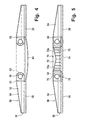
- Fig. 4 shows a second embodiment of a lamp according to the invention, which again Downlight can be, only essential elements are shown for lighting technology.
- the light pipe 50 has a circular ring shape.
- the associated one Cavity 52 is formed by a likewise annular roof wall 54, a radially outer one Side wall 56 and a light decoupling device 58 are formed, the roof wall 54 and the side wall 56 on the side of the cavity 52 are reflective.
- the Roof wall 54 is substantially straight in a radial cross section and to the light decoupling device 58 inclined so that the height of the cavity 52 to the radially outer Edge reduced.
- the Light decoupling device again consists of a prism plate 20, in the circular Prisms, as described above, are formed, which to the axis of symmetry of the Are concentric.
- a diaphragm ring 63 With radially aligned Slats arranged that the light is essentially perpendicular to the direction concentrated the prisms of the plate 20.
- the opening in the middle of the light guide 50 can be covered by a cover 64.
- the coupling reflectors 62 and the cover 64 can be partially translucent so that part of the light can also pass through the cover 64 exit. If the lamp is to have a circular ring shape overall, the cover 64 of course also fall away.
- FIG. 5 shows a modification of the embodiment according to FIG. 4, with the same elements are provided with the same reference numerals.
- this embodiment is in the inner recess of the annular hollow light guide 50, another hollow light guide 70 with a conical roof wall 72, the two reflecting inclined to each other in radial cross section Has roof wall sections 72a and 72b, opposite a light decoupling device 74 arranged.
- the design of the light guide 70 corresponds to that of the light guide 1 to 4.
- the ring lamp 60 is between the radially inner side of the light pipe 50 and the radially outer side of the light guide 70 arranged and coupled Light in both hollow light guides.
- the aperture ring 13 of the first embodiment described corresponds.
- bird-winged Reflectors 76 and 78 are provided above and below the ring lamp 60.
- the lower reflector 78 also serves to cover lamp 60 downward. Such a cover can also be omitted.
- the light decoupling devices 58 and 74 of the two light guides 50 and 70 are formed by a prism plate, the two light guides is common.
- ring lamps can also be used instead of ring lamps become.
- a collimating element emitting the light e.g. B. a collective mirror or a converging lens, in the focus of which the light source is arranged, or an aperture, radiates light essentially in the radial direction into the hollow light guide.
- 6 shows a possible embodiment of the invention for the example of a built-in lamp, the same design also being used for other types of luminaires can.
- 6 has a housing 80, which in a conventional manner with a mounting ring 82 and a fastening device 84 for fastening to a Blanket 86 is provided.
- a hollow light guide 88 is formed in the housing 80.
- the cavity 90 of this light guide 88 is through an annular roof wall 92, one of the Roof wall 92 opposite light decoupling device 94 and by part of the Sidewall of the housing 80 is formed, which has a sidewall 96 of the light guide 88 forms.
- the roof wall 92 and the side wall 96 are on the side facing the cavity 90 Reflective side.
- a lamp is through a central opening in the roof wall 92 98 inserted into the cavity 90 so that it emits its light directly into the cavity 90.
- the Lamp 98 can be, for example, a halogen incandescent lamp, a high-pressure lamp with a ceramic burner or the like. Ideally, the lamp 98 has the properties of a point Light source. Additional reflectors (not shown) can be assigned to lamp 98, to optimize the light radiation from the lamp into the cavity 90.
- the roof reflector is towards the center in this embodiment (seen from cavity 90) convexly curved so that the height of the cavity 90 and thus of the light guide 88 as a whole in the radially outward direction, i.e. away from lamp 98 decreases.
- the light decoupling device 94 as in the exemplary embodiments described above, formed by a prism plate 20, as described above.
- a prism plate 20 As described above.
- the light emitted by it becomes essentially radial, i.e. in vertical planes irradiated to the prisms 30 on the prisms, so that a in all radial planes Shielding is generated without the need for an additional element, such as an aperture.
- the lighting technology of the light guide and the light decoupling device in this embodiment otherwise corresponds essentially to that of the foregoing Embodiments and therefore will not be described again.
- the arrangement lamp 98 may vary. It can, as shown in Fig. 10, partially in the cavity 90 extend into, but also be completely received in the cavity 90 or itself are in the cavity 90 up to their end of the socket.
- Ballast 100 attached, which extends partially in an area where the height of the light guide 88 is reduced.
- the space in the housing 80 that passes through this decreasing height of the light pipe to the side facing away from the lamp 98 results, is therefore used advantageously for the ballast 100, or more generally to accommodate electrical and / or mechanical components, so that overall a lower overall height can be achieved. This concept can be taken for granted also used in the other embodiments described above become.
- a lamp can be positioned below the lamp 98 Cover (not shown) may be provided, which prevents light from the lamp 98 falls directly onto the prism plate 20 in an area in which the direction of the lines, which the prisms follow, changes relatively strongly over short distances, such as this is the case with circular prisms with a small diameter. Thereby prevents light in this area due to the non-ideality of the lamp 98 in Directions are incident on the prism plate that are not perpendicular to the lines of the prisms.
- the cover can be reflective in particular on the side facing the lamp 98 be formed and the light incident on them from the lamp 98 to the reflecting Reflect roof wall 92. If necessary, the one facing the prism plate 20 can also be used Be designed reflective so that even in the area immediately below the Lamp the light in the light pipe by reflection on the cover or on the prismatic plate 20 can spread.
- FIG. 7 shows a modification of the exemplary embodiment according to FIG. 6, this time for the example a pendant lamp.
- a roof wall 110 is provided as a boundary of the cavity 90, which, unlike in the exemplary embodiment according to FIG. 10, as seen from the cavity 90, not is convex, but concave.
- This embodiment also reduces the Height of cavity 90 in the direction from lamp 98 to the radially outer edge.
- the side walls 96 are eliminated since the roof wall 110 is directly on the Level of the side of the plate 18 facing the cavity 90 completes.
- Luminaires according to the invention can be used as circular lights, downlights, surface-mounted lights, Recessed lights or pendant lights can be carried out, to name a few examples.
- lamps instead of the lamps with reference to the previously described embodiments other types of light sources, e.g. Compact fluorescent lamps, High-pressure lamps, halogen incandescent lamps, light-emitting diodes, photoluminescent films or the like, be used.
- Compact fluorescent lamps High-pressure lamps
- halogen incandescent lamps e.g., halogen incandescent lamps, light-emitting diodes, photoluminescent films or the like.
Abstract
Description
Es kann vorgesehen sein, daß die Linien, welchen die Strukturelemente folgen, geschlossene Linien sind, welche vorzugsweise eine Symmetrie bezüglich einer Achse senkrecht zu der Grenzfläche aufweisen.
- Fig. 1
- zeigt schematisch eine Ansicht eines erfindungsgemäßen Downlights von unten,
- Fig. 2
- zeigt einen schematischen Querschnitt durch den Hohllichtleiter der Leuchte gemäß Fig. 1 entsprechend der Linie II-II in Fig. 1,
- Fig. 3
- zeigt schematisch einen vergrößerten Ausschnitt aus einem radialen Querschnitt der Prismenplatte,
- Fig. 4
- zeigt einen teilweisen Querschnitt durch eine zweite Ausführungsform einer erfindungsgemäßen Leuchte,
- Fig. 5
- zeigt einen teilweisen Querschnitt einer dritten Ausführungsform einer erfindungsgemäßen Leuchte,
- Fig. 6
- zeigt einen Querschnitt einer vierten Ausführungsform einer erfindungsgemäßen Leuchte in der Form einer Deckeneinbauleuchte,
- Fig. 7
- zeigt einen Querschnitt einer fünften Ausführungsform der erfindungsgemäßen Leuchte in der Form einer Pendelleuchte.
- 1
- Gehäuse
- 3
- Lichtaustrittsfläche
- 10
- Hohllichtleiter
- 12
- Hohlraum
- 13
- Blende
- 14
- Dachwand
- 14a, 14b
- Wandabschnitt
- 16
- Lichtauskoppeleinrichtung
- 20
- Prismenplatte
- 22
- Ringlampe
- 24
- Einkoppelreflektor
- 30
- Prisma
- 32, 32a, 32b
- Prismengrat
- 34, 34a, 34b
- Vertiefung
- 36
- Lamelle
- 50
- Hohllichtleiter
- 52
- Hohlraum
- 54
- Dachwand
- 56
- Seitenwand
- 58
- Lichtauskoppeleinrichtung
- 60
- Ringlampe
- 62
- Einkoppelreflektor
- 63
- Blendenkranz
- 64
- Abdeckung
- 70
- Hohllichtleiter
- 72
- Dachwand
- 72a, 72b
- Dachwandabschnitt
- 74
- Lichtauskoppeleinrichtung
- 75
- Blendenkranz
- 76
- oberer Reflektor
- 78
- unterer Reflektor
- 80
- Gehäuse
- 82
- Einbauring
- 84
- Befestigungseinrichtung
- 86
- Decke
- 88
- Hohllichtleiter
- 90
- Hohlraum
- 92
- Dachwand
- 94
- Lichtauskoppeleinrichtung
- 96
- Seitenwand
- 98
- Lampe
- 100
- Vorschaltgerät
- 110
- Dachwand
Claims (11)
- Leuchte zur Beleuchtung von Innenräumen mit einem nicht viereckigen Gehäuse (1; 80) und/oder einer nicht viereckigen Lichtaustrittsfläche (3), insbesondere Rundleuchte oder Downlight, welche mindestens einen Hohllichtleiter (10; 50; 70; 88) mit einem Hohlraum (12; 52; 90) sowie eine Lichteinstrahleinrichtung (13, 22; 60, 63; 98), welche eine oder mehrere Lichtquellen (22; 60; 98) umfaßt und von welcher Licht in den Hohlraum (12; 52; 90) des Hohllichtleiters eingestrahlt wird, und mindestens eine Lichtauskoppeleinrichtung (16; 58; 74; 94) aufweist, welche aus dem Hohlraum (12; 52; 90) Licht zum Austritt an einer nicht viereckigen Lichtaustrittsfläche (3) der Leuchte auskoppelt, wobei die Lichtauskoppeleinrichtung (16; 58; 74; 94) aus einem lichtdurchlässigen Material besteht und eine Grenzfläche zwischen zwei Medien mit unterschiedlichem Brechungsindex aufweist, die mit einer lichtbrechenden Struktur (30) aus linienförmigen lichtbrechenden Strukturelementen (30) versehen sind, wobei die lichtbrechende Struktur (30) zumindest in einer Fläche senkrecht zu der Lichtaustrittsfläche (3) der Leuchte und den Linien, welchen die lichtbrechenden Strukturelemente folgen, eine Lichtauskopplung oberhalb eines Grenzwinkels zu einer Senkrechten zu der Lichtaustrittsfläche (3) im wesentlichen verhindert und dadurch eine Abschirmung, bezogen auf diese Fläche bzw. Flächen, erzeugt, dadurch gekennzeichnet, daß die Lichteinstrahleinrichtung (13, 22; 60, 63; 98) so eingerichtet ist, daß das von ihr in den Hohlraum eingestrahlte und auf die Lichtauskoppeleinrichtung (16; 58; 74; 94) direkt einfallende Licht überwiegend in einer Richtung senkrecht zu den die Strukturelemente festlegenden Linien einfällt.
- Leuchte nach Anspruch 1, dadurch gekennzeichnet, daß die Linien, welchen die Strukturelemente (30) folgen, geschlossene Linien sind.
- Leuchte nach Anspruch 1 oder 2, dadurch gekennzeichnet, daß die lichtbrechenden Strukturelemente (30) entsprechend einer Symmetrie bezüglich einer Achse senkrecht zu der Grenzfläche mit der lichtbrechenden Struktur verlaufen und entlang dieser Symmetrieachse eine Lichteinstrahleinrichtung (98) angeordnet ist, welche das Licht überwiegend in einer Richtung senkrecht zu den die Strukturelemente (30) festlegenden Linien in den Hohlraum einstrahlt.
- Leuchte nach Anspruch 3, dadurch gekennzeichnet, daß die Strukturelemente (30) in der Form konzentrischer Kreise ausgebildet sind und die Lichteinstrahleinrichtung (98) entlang der Symmetrieachse angeordnet ist und das Licht überwiegend radial in den Hohlraum (90) einstrahlt.
- Leuchte nach Anspruch 4, dadurch gekennzeichnet, daß eine Lichtquelle (98) oder mehrere Lichtquellen entlang der Symmetrieachse angeordnet sind, welche Licht im wesentlichen oder überwiegend in radialer Richtung in den Hohlraum einstrahlen.
- Leuchte nach einem der Ansprüche 3 bis 5, dadurch gekennzeichnet, daß einer Lichtquelle ein fokussierendes Element, welches das von der Lichtquelle abgestrahlte Licht im wesentlichen auf die Symmetrieachse fokussiert, und eine Umlenkeinrichtung zugeordnet sind, welche das fokussierte Licht von der Lichtquelle in Richtungen senkrecht zu den Linien der Strukturelemente umlenkt.
- Leuchte nach Anspruch 1, dadurch gekennzeichnet, daß eine oder mehrere Lichtquellen (22) außerhalb des Hohllichtleiters entlang einem radial inneren oder äußeren Rand angeordnet sind und der Lichtquelle ein oder mehrere kollimierende Elemente (13) zugeordnet sind, welche das in den Hohlraum eingestrahlte Licht im wesentlichen auf Ebenen senkrecht zu den Linien der lichtbrechenden Strukturelemente (30) konzentrieren.
- Leuchte nach Anspruch 7, dadurch gekennzeichnet, daß zur Kollimierung des in den Hohlraum eingestrahlten Lichts Lamellen (13) vorgesehen sind, welche den Lichteinfall überwiegend auf die Richtung senkrecht zu den Linien der lichtbrechenden Strukturelemente (30) beschränken.
- Leuchte nach einem der Ansprüche 7 oder 8, dadurch gekennzeichnet, daß mehrere im wesentlichen punktförmige Lichtquellen entlang des inneren und/oder äußeren Rands des Hohllichtleiters (10; 50; 70) angeordnet sind, deren Licht in den Hohlraum (12; 52) eingestrahlt wird.
- Leuchte nach einem der Ansprüche 7 bis 9, dadurch gekennzeichnet, daß das Licht der Lichtquelle oder der Lichtquellen (22; 60; 98) im wesentlichen in einem radial äußeren Bereich auf die lichtbrechende Struktur (30) einfällt.
- Leuchte nach einem der Ansprüche 7 bis 10, dadurch gekennzeichnet, daß der Hohllichtleiter (10; 50; 70; 88) die Form eines Mehrecks hat, wobei an einer oder mehreren Seiten dieses Mehrecks eine Lichtquelle zur Lichteinkopplung angeordnet ist.
Applications Claiming Priority (2)
| Application Number | Priority Date | Filing Date | Title |
|---|---|---|---|
| DE10011676 | 2000-03-10 | ||
| DE10011676 | 2000-03-10 |
Publications (2)
| Publication Number | Publication Date |
|---|---|
| EP1132678A1 true EP1132678A1 (de) | 2001-09-12 |
| EP1132678B1 EP1132678B1 (de) | 2009-08-26 |
Family
ID=7634212
Family Applications (1)
| Application Number | Title | Priority Date | Filing Date |
|---|---|---|---|
| EP01105863A Expired - Lifetime EP1132678B1 (de) | 2000-03-10 | 2001-03-09 | Leuchte mit einem um einen Mittelpunkt symmetrisch angeordneten Hohllichtleiter und symmetrischer Lichteinstrahlung, insbesondere Rundleuchte |
Country Status (3)
| Country | Link |
|---|---|
| EP (1) | EP1132678B1 (de) |
| AT (1) | ATE441064T1 (de) |
| DE (1) | DE50115066D1 (de) |
Cited By (3)
| Publication number | Priority date | Publication date | Assignee | Title |
|---|---|---|---|---|
| EP2056136A3 (de) * | 2007-11-01 | 2010-10-27 | Kun Dian Photoelectric Enterprise Co. | Leuchte |
| EP2644976A1 (de) * | 2012-03-29 | 2013-10-02 | Siteco Beleuchtungstechnik GmbH | Leuchte mit Lichtabstrahlung in einen Randbereich |
| US10042113B2 (en) | 2012-11-07 | 2018-08-07 | Cooper Technologies Company | Edgelit lighting fixture and assembly |
Citations (2)
| Publication number | Priority date | Publication date | Assignee | Title |
|---|---|---|---|---|
| US5863114A (en) * | 1993-03-09 | 1999-01-26 | Fujitsu Limited | Light emissive panel unit |
| EP1055870A1 (de) * | 1999-05-25 | 2000-11-29 | Siteco Beleuchtungstechnik GmbH | Innenraumleuchte mit refraktiver Blendungsbegrenzung |
Family Cites Families (4)
| Publication number | Priority date | Publication date | Assignee | Title |
|---|---|---|---|---|
| ATE121178T1 (de) * | 1991-01-31 | 1995-04-15 | Siemens Ag | Leuchte. |
| ES2167674T3 (es) * | 1996-09-30 | 2002-05-16 | Koninkl Philips Electronics Nv | Luminaria. |
| ATE269957T1 (de) * | 1998-08-24 | 2004-07-15 | Zumtobel Staff Gmbh | Leuchte mit lichtleitelement |
| EP1130312B1 (de) * | 2000-03-03 | 2017-05-31 | Siteco Beleuchtungstechnik GmbH | Leuchte mit einer um einen Mittelpunkt symmetrisch angeordneten Lichtaustrittsfläche, insbesondere Rundleuchte |
-
2001
- 2001-03-09 DE DE50115066T patent/DE50115066D1/de not_active Expired - Lifetime
- 2001-03-09 AT AT01105863T patent/ATE441064T1/de active
- 2001-03-09 EP EP01105863A patent/EP1132678B1/de not_active Expired - Lifetime
Patent Citations (2)
| Publication number | Priority date | Publication date | Assignee | Title |
|---|---|---|---|---|
| US5863114A (en) * | 1993-03-09 | 1999-01-26 | Fujitsu Limited | Light emissive panel unit |
| EP1055870A1 (de) * | 1999-05-25 | 2000-11-29 | Siteco Beleuchtungstechnik GmbH | Innenraumleuchte mit refraktiver Blendungsbegrenzung |
Cited By (5)
| Publication number | Priority date | Publication date | Assignee | Title |
|---|---|---|---|---|
| EP2056136A3 (de) * | 2007-11-01 | 2010-10-27 | Kun Dian Photoelectric Enterprise Co. | Leuchte |
| EP2644976A1 (de) * | 2012-03-29 | 2013-10-02 | Siteco Beleuchtungstechnik GmbH | Leuchte mit Lichtabstrahlung in einen Randbereich |
| US10042113B2 (en) | 2012-11-07 | 2018-08-07 | Cooper Technologies Company | Edgelit lighting fixture and assembly |
| US10473850B2 (en) | 2012-11-07 | 2019-11-12 | Eaton Intelligent Power Limited | Edgelit lighting fixture and assembly |
| EP2917633B1 (de) * | 2012-11-07 | 2022-01-05 | Signify Holding B.V. | Kantenbeleuchteter leuchtkörper |
Also Published As
| Publication number | Publication date |
|---|---|
| EP1132678B1 (de) | 2009-08-26 |
| DE50115066D1 (de) | 2009-10-08 |
| ATE441064T1 (de) | 2009-09-15 |
Similar Documents
| Publication | Publication Date | Title |
|---|---|---|
| DE4342928C2 (de) | Relflektoranordnung mit einer darin angeordneten Lichtquelle für eine Fahrzeugleuchte | |
| DE2238589C3 (de) | Lichtstreuende ebene Abdeckplatte für Deckenleuchten | |
| EP0762515A2 (de) | Optikkörper für mindestens eine LED | |
| EP1110031B1 (de) | Leuchte mit lichtleitelement | |
| EP3037719B1 (de) | Led-linsenkörper zur erzeugung eines direkt- und indirektlichtanteils | |
| DE19961491B4 (de) | Innenraumleuchte mit Hohllichtleiter | |
| EP1059484B1 (de) | Leuchte mit breitstrahlender Lichtstärkeverteilung | |
| DE102005047746A1 (de) | Anordnung zum gezielten Entblenden von Außenleuchten in vertikaler und horizontaler Achse | |
| DE10011304B4 (de) | Leuchte mit inhomogener Lichtabstrahlung | |
| DE4312889B4 (de) | Vorwiegend direkt strahlende Leuchte mit einem abgehängten Lichtleitkörper | |
| DE10011378B4 (de) | Hohllichtleiterleuchte mit indirekter Lichtabstrahlung | |
| EP1106905B1 (de) | Leuchte | |
| EP1120600B1 (de) | Lichtleiterleuchte mit einer linearen Prismenstruktur | |
| EP1132678B1 (de) | Leuchte mit einem um einen Mittelpunkt symmetrisch angeordneten Hohllichtleiter und symmetrischer Lichteinstrahlung, insbesondere Rundleuchte | |
| DE102006030646B4 (de) | Innenraumleuchte zur Ausleuchtung einer Wand oder Decke | |
| EP1275898A2 (de) | Innenraumleuchte mit variablem, indirektem Lichtanteil | |
| DE202005011293U1 (de) | Leuchte mit einem rohrförmigen Lichtleitelement | |
| EP1132679B1 (de) | Leuchtensystem | |
| EP1130312B1 (de) | Leuchte mit einer um einen Mittelpunkt symmetrisch angeordneten Lichtaustrittsfläche, insbesondere Rundleuchte | |
| EP1106916B1 (de) | Leuchte mit einer abschirmenden lichtbrechenden Struktur und einer strahlbegrenzenden Reflektoranordnung | |
| EP1130311B1 (de) | Leuchte mit einer mehreckigen Lichtausstrittsfläche und einer geradlinigen Prismenstruktur | |
| WO1992018805A1 (de) | Leuchtenabdeckung, insbesondere für leuchtstofflampen | |
| EP1130310A2 (de) | Hohllichtleiterleuchte mit in den Hohlraum integrierter Lampe | |
| EP1055865B1 (de) | Hängeleuchte mit indirekter Lichtabstrahlung | |
| DE10353644A1 (de) | Leuchte mit einem Entblendungskörper |
Legal Events
| Date | Code | Title | Description |
|---|---|---|---|
| PUAI | Public reference made under article 153(3) epc to a published international application that has entered the european phase |
Free format text: ORIGINAL CODE: 0009012 |
|
| AK | Designated contracting states |
Kind code of ref document: A1 Designated state(s): AT BE CH CY DE DK ES FI FR GB GR IE IT LI LU MC NL PT SE TR |
|
| AX | Request for extension of the european patent |
Free format text: AL;LT;LV;MK;RO;SI |
|
| 17P | Request for examination filed |
Effective date: 20020116 |
|
| AKX | Designation fees paid |
Free format text: AT BE CH CY DE DK ES FI FR GB GR IE IT LI LU MC NL PT SE TR |
|
| GRAP | Despatch of communication of intention to grant a patent |
Free format text: ORIGINAL CODE: EPIDOSNIGR1 |
|
| GRAS | Grant fee paid |
Free format text: ORIGINAL CODE: EPIDOSNIGR3 |
|
| GRAA | (expected) grant |
Free format text: ORIGINAL CODE: 0009210 |
|
| AK | Designated contracting states |
Kind code of ref document: B1 Designated state(s): AT BE CH CY DE DK ES FI FR GB GR IE IT LI LU MC NL PT SE TR |
|
| REG | Reference to a national code |
Ref country code: GB Ref legal event code: FG4D Free format text: NOT ENGLISH |
|
| REG | Reference to a national code |
Ref country code: CH Ref legal event code: NV Representative=s name: ISLER & PEDRAZZINI AG Ref country code: CH Ref legal event code: EP |
|
| REG | Reference to a national code |
Ref country code: IE Ref legal event code: FG4D Free format text: LANGUAGE OF EP DOCUMENT: GERMAN |
|
| REF | Corresponds to: |
Ref document number: 50115066 Country of ref document: DE Date of ref document: 20091008 Kind code of ref document: P |
|
| PG25 | Lapsed in a contracting state [announced via postgrant information from national office to epo] |
Ref country code: FI Free format text: LAPSE BECAUSE OF FAILURE TO SUBMIT A TRANSLATION OF THE DESCRIPTION OR TO PAY THE FEE WITHIN THE PRESCRIBED TIME-LIMIT Effective date: 20090826 Ref country code: SE Free format text: LAPSE BECAUSE OF FAILURE TO SUBMIT A TRANSLATION OF THE DESCRIPTION OR TO PAY THE FEE WITHIN THE PRESCRIBED TIME-LIMIT Effective date: 20090826 |
|
| NLV1 | Nl: lapsed or annulled due to failure to fulfill the requirements of art. 29p and 29m of the patents act | ||
| PG25 | Lapsed in a contracting state [announced via postgrant information from national office to epo] |
Ref country code: NL Free format text: LAPSE BECAUSE OF FAILURE TO SUBMIT A TRANSLATION OF THE DESCRIPTION OR TO PAY THE FEE WITHIN THE PRESCRIBED TIME-LIMIT Effective date: 20090826 |
|
| PG25 | Lapsed in a contracting state [announced via postgrant information from national office to epo] |
Ref country code: PT Free format text: LAPSE BECAUSE OF FAILURE TO SUBMIT A TRANSLATION OF THE DESCRIPTION OR TO PAY THE FEE WITHIN THE PRESCRIBED TIME-LIMIT Effective date: 20091228 Ref country code: CY Free format text: LAPSE BECAUSE OF FAILURE TO SUBMIT A TRANSLATION OF THE DESCRIPTION OR TO PAY THE FEE WITHIN THE PRESCRIBED TIME-LIMIT Effective date: 20090826 |
|
| REG | Reference to a national code |
Ref country code: IE Ref legal event code: FD4D |
|
| PG25 | Lapsed in a contracting state [announced via postgrant information from national office to epo] |
Ref country code: ES Free format text: LAPSE BECAUSE OF FAILURE TO SUBMIT A TRANSLATION OF THE DESCRIPTION OR TO PAY THE FEE WITHIN THE PRESCRIBED TIME-LIMIT Effective date: 20091207 Ref country code: IE Free format text: LAPSE BECAUSE OF FAILURE TO SUBMIT A TRANSLATION OF THE DESCRIPTION OR TO PAY THE FEE WITHIN THE PRESCRIBED TIME-LIMIT Effective date: 20090826 Ref country code: DK Free format text: LAPSE BECAUSE OF FAILURE TO SUBMIT A TRANSLATION OF THE DESCRIPTION OR TO PAY THE FEE WITHIN THE PRESCRIBED TIME-LIMIT Effective date: 20090826 |
|
| PLBE | No opposition filed within time limit |
Free format text: ORIGINAL CODE: 0009261 |
|
| STAA | Information on the status of an ep patent application or granted ep patent |
Free format text: STATUS: NO OPPOSITION FILED WITHIN TIME LIMIT |
|
| 26N | No opposition filed |
Effective date: 20100527 |
|
| BERE | Be: lapsed |
Owner name: SITECO BELEUCHTUNGSTECHNIK G.M.B.H. Effective date: 20100331 |
|
| PG25 | Lapsed in a contracting state [announced via postgrant information from national office to epo] |
Ref country code: GR Free format text: LAPSE BECAUSE OF FAILURE TO SUBMIT A TRANSLATION OF THE DESCRIPTION OR TO PAY THE FEE WITHIN THE PRESCRIBED TIME-LIMIT Effective date: 20091127 Ref country code: MC Free format text: LAPSE BECAUSE OF NON-PAYMENT OF DUE FEES Effective date: 20100331 |
|
| REG | Reference to a national code |
Ref country code: FR Ref legal event code: ST Effective date: 20101130 |
|
| PG25 | Lapsed in a contracting state [announced via postgrant information from national office to epo] |
Ref country code: FR Free format text: LAPSE BECAUSE OF NON-PAYMENT OF DUE FEES Effective date: 20100331 |
|
| PG25 | Lapsed in a contracting state [announced via postgrant information from national office to epo] |
Ref country code: BE Free format text: LAPSE BECAUSE OF NON-PAYMENT OF DUE FEES Effective date: 20100331 |
|
| REG | Reference to a national code |
Ref country code: DE Ref legal event code: R082 Ref document number: 50115066 Country of ref document: DE Representative=s name: BOEHMERT & BOEHMERT, DE |
|
| REG | Reference to a national code |
Ref country code: DE Ref legal event code: R081 Ref document number: 50115066 Country of ref document: DE Owner name: SITECO BELEUCHTUNGSTECHNIK GMBH, DE Free format text: FORMER OWNER: SITECO BELEUCHTUNGSTECHNIK GMBH, 83301 TRAUNREUT, DE Effective date: 20111109 Ref country code: DE Ref legal event code: R082 Ref document number: 50115066 Country of ref document: DE Representative=s name: BOEHMERT & BOEHMERT, DE Effective date: 20111109 Ref country code: DE Ref legal event code: R082 Ref document number: 50115066 Country of ref document: DE Representative=s name: BOEHMERT & BOEHMERT ANWALTSPARTNERSCHAFT MBB -, DE Effective date: 20111109 |
|
| REG | Reference to a national code |
Ref country code: CH Ref legal event code: PUE Owner name: SITECO BETEILIGUNGSVERWALTUNGS GMBH Free format text: SITECO BELEUCHTUNGSTECHNIK GMBH#OHMSTRASSE 50#83301 TRAUNREUT (DE) -TRANSFER TO- SITECO BETEILIGUNGSVERWALTUNGS GMBH#GEORG-SIMON-OHM-STR. 50#83301 TRAUNREUT (DE) |
|
| REG | Reference to a national code |
Ref country code: CH Ref legal event code: PFA Owner name: SITECO BELEUCHTUNGSTECHNIK GMBH Free format text: SITECO BETEILIGUNGSVERWALTUNGS GMBH#GEORG-SIMON-OHM-STR. 50#83301 TRAUNREUT (DE) -TRANSFER TO- SITECO BELEUCHTUNGSTECHNIK GMBH#GEORG-SIMON-OHM-STR. 50#83301 TRAUNREUT (DE) |
|
| PG25 | Lapsed in a contracting state [announced via postgrant information from national office to epo] |
Ref country code: LU Free format text: LAPSE BECAUSE OF NON-PAYMENT OF DUE FEES Effective date: 20100309 |
|
| PG25 | Lapsed in a contracting state [announced via postgrant information from national office to epo] |
Ref country code: TR Free format text: LAPSE BECAUSE OF FAILURE TO SUBMIT A TRANSLATION OF THE DESCRIPTION OR TO PAY THE FEE WITHIN THE PRESCRIBED TIME-LIMIT Effective date: 20090826 |
|
| REG | Reference to a national code |
Ref country code: GB Ref legal event code: 732E Free format text: REGISTERED BETWEEN 20121004 AND 20121010 |
|
| REG | Reference to a national code |
Ref country code: AT Ref legal event code: PC Ref document number: 441064 Country of ref document: AT Kind code of ref document: T Owner name: SITECO BELEUCHTUNGSTECHNIK GMBH, DE Effective date: 20121019 |
|
| PGFP | Annual fee paid to national office [announced via postgrant information from national office to epo] |
Ref country code: DE Payment date: 20170322 Year of fee payment: 17 Ref country code: CH Payment date: 20170322 Year of fee payment: 17 |
|
| PGFP | Annual fee paid to national office [announced via postgrant information from national office to epo] |
Ref country code: GB Payment date: 20170322 Year of fee payment: 17 Ref country code: AT Payment date: 20170322 Year of fee payment: 17 |
|
| PGFP | Annual fee paid to national office [announced via postgrant information from national office to epo] |
Ref country code: IT Payment date: 20170323 Year of fee payment: 17 |
|
| REG | Reference to a national code |
Ref country code: DE Ref legal event code: R119 Ref document number: 50115066 Country of ref document: DE |
|
| REG | Reference to a national code |
Ref country code: CH Ref legal event code: PL |
|
| REG | Reference to a national code |
Ref country code: AT Ref legal event code: MM01 Ref document number: 441064 Country of ref document: AT Kind code of ref document: T Effective date: 20180309 |
|
| GBPC | Gb: european patent ceased through non-payment of renewal fee |
Effective date: 20180309 |
|
| PG25 | Lapsed in a contracting state [announced via postgrant information from national office to epo] |
Ref country code: AT Free format text: LAPSE BECAUSE OF NON-PAYMENT OF DUE FEES Effective date: 20180309 Ref country code: DE Free format text: LAPSE BECAUSE OF NON-PAYMENT OF DUE FEES Effective date: 20181002 |
|
| PG25 | Lapsed in a contracting state [announced via postgrant information from national office to epo] |
Ref country code: GB Free format text: LAPSE BECAUSE OF NON-PAYMENT OF DUE FEES Effective date: 20180309 Ref country code: IT Free format text: LAPSE BECAUSE OF NON-PAYMENT OF DUE FEES Effective date: 20180309 Ref country code: CH Free format text: LAPSE BECAUSE OF NON-PAYMENT OF DUE FEES Effective date: 20180331 Ref country code: LI Free format text: LAPSE BECAUSE OF NON-PAYMENT OF DUE FEES Effective date: 20180331 |