EP1132595A2 - Heat and electric power supply system and operation method thereof - Google Patents
Heat and electric power supply system and operation method thereof Download PDFInfo
- Publication number
- EP1132595A2 EP1132595A2 EP01105539A EP01105539A EP1132595A2 EP 1132595 A2 EP1132595 A2 EP 1132595A2 EP 01105539 A EP01105539 A EP 01105539A EP 01105539 A EP01105539 A EP 01105539A EP 1132595 A2 EP1132595 A2 EP 1132595A2
- Authority
- EP
- European Patent Office
- Prior art keywords
- heat
- equipment
- gas turbine
- electric power
- water
- Prior art date
- Legal status (The legal status is an assumption and is not a legal conclusion. Google has not performed a legal analysis and makes no representation as to the accuracy of the status listed.)
- Granted
Links
- 238000000034 method Methods 0.000 title claims description 23
- XLYOFNOQVPJJNP-UHFFFAOYSA-N water Substances O XLYOFNOQVPJJNP-UHFFFAOYSA-N 0.000 claims abstract description 164
- 230000001172 regenerating effect Effects 0.000 claims abstract description 51
- 238000001816 cooling Methods 0.000 claims abstract description 32
- 239000007921 spray Substances 0.000 claims abstract description 22
- 238000005507 spraying Methods 0.000 claims abstract description 15
- 239000007789 gas Substances 0.000 claims description 100
- 238000010521 absorption reaction Methods 0.000 claims description 64
- 238000010248 power generation Methods 0.000 claims description 52
- 239000000498 cooling water Substances 0.000 claims description 13
- 238000009825 accumulation Methods 0.000 claims description 12
- 239000008236 heating water Substances 0.000 claims description 7
- 239000000446 fuel Substances 0.000 claims description 4
- 238000011144 upstream manufacturing Methods 0.000 claims description 2
- 239000000567 combustion gas Substances 0.000 claims 1
- 238000001179 sorption measurement Methods 0.000 abstract description 4
- 238000002347 injection Methods 0.000 abstract 2
- 239000007924 injection Substances 0.000 abstract 2
- 239000003570 air Substances 0.000 description 80
- 230000007423 decrease Effects 0.000 description 20
- 238000010276 construction Methods 0.000 description 17
- 238000011084 recovery Methods 0.000 description 16
- 230000000694 effects Effects 0.000 description 14
- MWUXSHHQAYIFBG-UHFFFAOYSA-N nitrogen oxide Inorganic materials O=[N] MWUXSHHQAYIFBG-UHFFFAOYSA-N 0.000 description 10
- 238000002485 combustion reaction Methods 0.000 description 9
- 238000010586 diagram Methods 0.000 description 6
- 238000004378 air conditioning Methods 0.000 description 5
- 229920006395 saturated elastomer Polymers 0.000 description 5
- 230000003247 decreasing effect Effects 0.000 description 4
- 230000006835 compression Effects 0.000 description 3
- 238000007906 compression Methods 0.000 description 3
- 239000000428 dust Substances 0.000 description 3
- 230000005611 electricity Effects 0.000 description 3
- 239000012080 ambient air Substances 0.000 description 2
- 238000004140 cleaning Methods 0.000 description 2
- 239000000203 mixture Substances 0.000 description 2
- 238000010979 pH adjustment Methods 0.000 description 2
- 230000001603 reducing effect Effects 0.000 description 2
- 230000001105 regulatory effect Effects 0.000 description 2
- 239000002904 solvent Substances 0.000 description 2
- 239000006096 absorbing agent Substances 0.000 description 1
- 238000007796 conventional method Methods 0.000 description 1
- 238000013016 damping Methods 0.000 description 1
- 239000011521 glass Substances 0.000 description 1
- 239000007788 liquid Substances 0.000 description 1
- 230000000630 rising effect Effects 0.000 description 1
- 230000001954 sterilising effect Effects 0.000 description 1
- 238000004659 sterilization and disinfection Methods 0.000 description 1
- 230000001629 suppression Effects 0.000 description 1
Images


Classifications
-
- F—MECHANICAL ENGINEERING; LIGHTING; HEATING; WEAPONS; BLASTING
- F02—COMBUSTION ENGINES; HOT-GAS OR COMBUSTION-PRODUCT ENGINE PLANTS
- F02C—GAS-TURBINE PLANTS; AIR INTAKES FOR JET-PROPULSION PLANTS; CONTROLLING FUEL SUPPLY IN AIR-BREATHING JET-PROPULSION PLANTS
- F02C6/00—Plural gas-turbine plants; Combinations of gas-turbine plants with other apparatus; Adaptations of gas-turbine plants for special use
- F02C6/18—Plural gas-turbine plants; Combinations of gas-turbine plants with other apparatus; Adaptations of gas-turbine plants for special use using the waste heat of gas-turbine plants outside the plants themselves, e.g. gas-turbine power heat plants
-
- F—MECHANICAL ENGINEERING; LIGHTING; HEATING; WEAPONS; BLASTING
- F25—REFRIGERATION OR COOLING; COMBINED HEATING AND REFRIGERATION SYSTEMS; HEAT PUMP SYSTEMS; MANUFACTURE OR STORAGE OF ICE; LIQUEFACTION SOLIDIFICATION OF GASES
- F25B—REFRIGERATION MACHINES, PLANTS OR SYSTEMS; COMBINED HEATING AND REFRIGERATION SYSTEMS; HEAT PUMP SYSTEMS
- F25B27/00—Machines, plants or systems, using particular sources of energy
- F25B27/02—Machines, plants or systems, using particular sources of energy using waste heat, e.g. from internal-combustion engines
-
- F—MECHANICAL ENGINEERING; LIGHTING; HEATING; WEAPONS; BLASTING
- F05—INDEXING SCHEMES RELATING TO ENGINES OR PUMPS IN VARIOUS SUBCLASSES OF CLASSES F01-F04
- F05D—INDEXING SCHEME FOR ASPECTS RELATING TO NON-POSITIVE-DISPLACEMENT MACHINES OR ENGINES, GAS-TURBINES OR JET-PROPULSION PLANTS
- F05D2260/00—Function
- F05D2260/20—Heat transfer, e.g. cooling
- F05D2260/211—Heat transfer, e.g. cooling by intercooling, e.g. during a compression cycle
-
- F—MECHANICAL ENGINEERING; LIGHTING; HEATING; WEAPONS; BLASTING
- F05—INDEXING SCHEMES RELATING TO ENGINES OR PUMPS IN VARIOUS SUBCLASSES OF CLASSES F01-F04
- F05D—INDEXING SCHEME FOR ASPECTS RELATING TO NON-POSITIVE-DISPLACEMENT MACHINES OR ENGINES, GAS-TURBINES OR JET-PROPULSION PLANTS
- F05D2260/00—Function
- F05D2260/20—Heat transfer, e.g. cooling
- F05D2260/212—Heat transfer, e.g. cooling by water injection
-
- F—MECHANICAL ENGINEERING; LIGHTING; HEATING; WEAPONS; BLASTING
- F25—REFRIGERATION OR COOLING; COMBINED HEATING AND REFRIGERATION SYSTEMS; HEAT PUMP SYSTEMS; MANUFACTURE OR STORAGE OF ICE; LIQUEFACTION SOLIDIFICATION OF GASES
- F25B—REFRIGERATION MACHINES, PLANTS OR SYSTEMS; COMBINED HEATING AND REFRIGERATION SYSTEMS; HEAT PUMP SYSTEMS
- F25B15/00—Sorption machines, plants or systems, operating continuously, e.g. absorption type
- F25B15/02—Sorption machines, plants or systems, operating continuously, e.g. absorption type without inert gas
- F25B15/06—Sorption machines, plants or systems, operating continuously, e.g. absorption type without inert gas the refrigerant being water vapour evaporated from a salt solution, e.g. lithium bromide
-
- Y—GENERAL TAGGING OF NEW TECHNOLOGICAL DEVELOPMENTS; GENERAL TAGGING OF CROSS-SECTIONAL TECHNOLOGIES SPANNING OVER SEVERAL SECTIONS OF THE IPC; TECHNICAL SUBJECTS COVERED BY FORMER USPC CROSS-REFERENCE ART COLLECTIONS [XRACs] AND DIGESTS
- Y02—TECHNOLOGIES OR APPLICATIONS FOR MITIGATION OR ADAPTATION AGAINST CLIMATE CHANGE
- Y02A—TECHNOLOGIES FOR ADAPTATION TO CLIMATE CHANGE
- Y02A30/00—Adapting or protecting infrastructure or their operation
- Y02A30/27—Relating to heating, ventilation or air conditioning [HVAC] technologies
- Y02A30/274—Relating to heating, ventilation or air conditioning [HVAC] technologies using waste energy, e.g. from internal combustion engine
-
- Y—GENERAL TAGGING OF NEW TECHNOLOGICAL DEVELOPMENTS; GENERAL TAGGING OF CROSS-SECTIONAL TECHNOLOGIES SPANNING OVER SEVERAL SECTIONS OF THE IPC; TECHNICAL SUBJECTS COVERED BY FORMER USPC CROSS-REFERENCE ART COLLECTIONS [XRACs] AND DIGESTS
- Y02—TECHNOLOGIES OR APPLICATIONS FOR MITIGATION OR ADAPTATION AGAINST CLIMATE CHANGE
- Y02E—REDUCTION OF GREENHOUSE GAS [GHG] EMISSIONS, RELATED TO ENERGY GENERATION, TRANSMISSION OR DISTRIBUTION
- Y02E20/00—Combustion technologies with mitigation potential
- Y02E20/14—Combined heat and power generation [CHP]
Definitions
- the present invention relates to a heat and electric power supply system which generates and supplies heat and electric power at the same time and a method of operating the system.
- a cold/heat/electric power supply system which supplies electric power and thermal energy such as cold/heat at the same time can be realized by a combination of an absorption refrigerator which is made it possible to supply cold water/hot water at the same time by providing a change-over valve inside for example, and a generator which is driven by an internal combustion engine such as a diesel engine, gas engine, gas turbine or the like.
- a small-sized regenerative gas turbine provided with a regenerative heat exchanger is developed and a cold/heat/electric power supply system using such a turbine also is been studied.
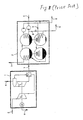
- FIG. 8 An example of a conventional cold/heat/electric power supply system is shown in Fig. 8, which employs a generator driven by a small-sized regenerative gas turbine and an absorption refrigerator.
- an exhaust gas 7 from the regenerative gas turbine 1 is led to the absorption refrigerator 2 which recovers heat from the exhaust gas in a regenerator and generates hot water 9 in a condenser and cold water 8 in an evaporator.
- the maximum power generation output is limited by the maximum output of the regenerative gas turbine and it is impossible to increase the power generation output and to increase energy effectively utilized, even in the case where a demand such as air conditioning has decreased in middle season whereby a demand of cold/heat has decreased.
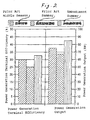
- Fig. 2 some factors representative of the performance of the conventional system is shown in prior art items of Fig. 2 in the form of comparison of power generation efficiency and output between in the case where the above-mentioned system is operated in middle season (atmospheric temperature 15°C and humidity 30%) and in the case where the system is operated in summer (atmospheric temperature 38°C and humidity 60%).
- the air density decreases as the temperature increases and a mass flow rate of the air taken in a compressor of the regenerative gas turbine decreases, so that a recovery heat amount in a regenerative heat exchanger of the regenerative gas turbine and turbine output decrease and both the power generation terminal output and power generation efficiency change greatly, as shown in Fig. 2.
- the present invention is made in view of the above-mentioned points, and an object of the present invention is to provide a heat and electric power supply system and an operation method thereof which enables the power generation output to increase.
- a heat and electric power supply system comprises gas turbine equipment generating electric power, absorption refrigerating equipment recovering exhaust heat from the gas turbine equipment and generating thermal energy, and air cooling equipment fluidly connected to the gas turbine and the absorption refrigerating equipment and cooling air for power generation in the gas turbine equipment with the thermal energy generated in the absorption refrigerating equipment.
- An example of the air cooling equipment is a spray device for spraying cold water from the absorption refrigerator onto the air to be taken in a compressor of the regenerative gas turbine or a humidifier for humidifying the air from the compressor with hot water from the absorption refrigerator.
- the system can be provided with a heat recovering device for recovering heat from exhaust gas of the adsorption refrigerator and/or an accumulation type heat exchanger for recovering accumulating heat from exhaust gas of the adsorption refrigerator.
- the operation method of a heat and electric power supply system which comprises gas turbine equipment and absorption refrigerating equipment recovering exhaust heat of the gas turbine equipment cooling or heating water, is characterized in that intake air of the gas turbine equipment is cooled by spraying or injecting the water generated in the absorption refrigerator onto the intake air.
- An example of the water used for cooling the intake water is at least one of cold water and hot water.
- a heat and electric power supply system that is, a system or equipment which is able to jointly supply thermal energy (cold and heat) and electric power, of each embodiment of the present invention relates to a so-called co-generation system.
- the co-generation system is provided with an electric power generating function to supply electric power to a demandant such as a house, glass culture farm house, small-sized factory, each section of collective houses, hospital, hotel, combined sport facilities, or the like, and supplies cold energy and heat energy to facilities such as air conditioning equipment.
- a demandant such as a house, glass culture farm house, small-sized factory, each section of collective houses, hospital, hotel, combined sport facilities, or the like
- a system which employs a regenerative gas turbine as a motor will be described hereunder.
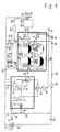
- FIG. 1 shows the cold/heat/electric power supply system provided with a regenerative gas turbine 1 driving a generator 16, and an absorption refrigerator 2 supplied with water through a feed water treating apparatus 30 and supplying a demandant such as an air conditioning apparatus or the like with cold water 8 and hot water 9. Further, the system and its operation will be described in detail, referring to Fig. 1.
- a spray device 31 for intake air is provided at an inlet of the regenerative gas turbine 1.
- the spray device 31 sprays cold water onto the air 3 taken in the gas turbine 1 to humidify and cool the air according to the circumference and operation conditions.
- the air taken in, that is, intake air is compressed by a compressor 11 and led to a humidifier 12.
- a humidifier 12 hot water of necessary quantity is sprayed according to operation conditions such as power demand or the like and able to humidify the intake air.
- the intake air exiting from the humidifier 12 is led into a regenerative heat exchanger 13 in which the intake air recovers the heat of exhaust gas from a turbine 15 and is preheated thereby.
- the preheated intake air is mixed with fuel 4 in a combustor 14 and the mixture is burnt therein and flows into the turbine 15 as a high temperature gas.
- the turbine 15 the high temperature gas expands to work, whereby output is obtained.
- the output drives the compressor 11 and the generator 16.
- the exhaust gas exiting from the turbine 15 is led into a regenerator 21 of the absorption refrigerator 2 as gas turbine exhaust gas 70 after the heat of the exhaust gas has been recovered in the regenerative heat exchanger 13.
- the heat of the turbine exhaust gas 70 is recovered and finally exhausted out of the system as absorption refrigerator exhaust gas 71.
- the regenerator 21 recovers heat from the gas turbine exhaust gas 70 and evaporates a solvent from a dilute solution 29 to generate vapor 28.
- the vapor 28 generated in the regenerator is led to a condenser 22.
- the absorption refrigerator 2 has equipments for supplying feed water 50 from outside the equipment as treatment-finished feed water 51 by a feed pump 25 after treatment such as dust removal, water softening or the like is effected in the eed water treating apparatus 30, and is constructed so that water can be compensated by the amount of water consumed by the demandant or in the regenerative gas turbine 1.
- the feed water treating apparatus 30 is constructed so that the condensate 52 exhausted and recovered from a demandant such as air conditioning apparatus or the like also can be jointly supplied in addition to the feed water 50 from outside.
- the supplemented treatment-finished water 51 and the water which is circulated by a recirculation pump 24 inside the absorption refrigerator 2 cool the vapor 28 in the condenser 22 and receive thereby heat from the vapor to turn into hot water 9.
- the generated hot water 9 is led to an evaporator 23 after the hot water of a quantity necessary for a demandant and the regenerative gas turbine 1 is branched by a hot water bypass valve 26 provided inside the absorption refrigerator 2.
- the inside pressure of the evaporator 23 is reduced to be about vacuum and the solvent condensed in the condenser 22 evaporates due to reduced pressure and is turned into vapor 28 again. In this case, latent heat is taken out from the hot water 9, whereby water exiting from the evaporator 23 becomes cold water 8.
- the vapor generated in the evaporator 23 is led to an absorber 20 and absorbed in a solution concentrated in the regenerator 21 thereby to become a dilute solution 29.
- the dilute solution 29 is sent to the regenerator 21.
- the cold water 8 generated in the evaporator 23 is recirculated by an optimum quantity regulated by a cold water bypass valve 27 according to the operation conditions inside the absorption refrigerator 2, and then the remaining cold water is taken out of the absorption refrigerator 2 and supplied to a demandant such as an air conditioning apparatus or the like or to the regenerative gas turbine 1 through a branch valve 33.
- a supply ratio of cold water/hot water can be set freely by regulating the opening of each of the hot water bypass valve 26 and cold water bypass valve 27, so that in the case where any of cold water and hot water is generated in excess, the excess heat can be taken in any form such as cold water or hot water.
- the excess heat is taken out as cold water, and the cold water branch valve 33 is opened and gas turbine supply cold water 80 is supplied to the spray device 31 for intake air through a cold water feed pump 34 to humidify and cool the intake air by spray water 81 for intake air, whereby it is effective to reduce power necessary for the compressor by reducing a thermal drop in the compressor of the regenerative gas turbine and improve the power generation terminal output and power generation efficiency. Further, since a mass flow increases by the humidification, the effect become large without greatly decreasing the intake air temperature, as a result, there is an advantage that only very small amount of cold water is consumed.
- the spray water 81 for intake air can attain a reducing effect of the compressor power through a change in specific heat ratio due to humidification even if the spray water 81 is sprayed at a very small flow rate such as about 0.01 wt% of the air mass flow rate.
- a very small flow rate such as about 0.01 wt% of the air mass flow rate.
- the intake air of the regenerative gas turbine 1 is humidified to an extent that the intake air reaches the saturated steam pressure.
- a temperature decrease in the intake air by this humidification is about 0.2°C or so, however, the compressor efficiency is improved 0.4 to 0.5% at relative value by decrease in specific heat ratio, and about 1.2% of the compressor power can be reduced.
- a flow rate of water of about 0.2 wt% of the air mass flow rate is optimum.
- large diameter droplets are discharged out and recovered as drain, and fine droplets are delivered through the compressor 11 together with the intake air and evaporate at the delivery port, whereby the same effect as water of a very small quantity has been humidified by the humidifier 12 can be attained.
- Table 1 there is shown an operation example in which the excess heat is taken out as cold water and hot water, intake air is spray-cooled and humidified at the compressor delivery port, whereby the power generation output and power generation efficiency are improved.
- a cold/heat/electric power supply system which employs a regenerative gas turbine-driven generator of rated revolution of 65,000 rpm having a generation output of 75 kW under the condition that the surrounding air temperature is 15°C and the relative humidity is 30%.
- a row of a prior art shows results in the case where the operation method of improving electricity output and power generation efficiency according to the present embodiment is not taken.
- a row of the present embodiment shows results in the case where the operation method of improving electricity output and power generation efficiency according to the present embodiment is taken.
- a row of effects shows, by relative values (%) to the prior art, the results in the case where the operation method of the present embodiment is applied.
- cold water of 7°C is supplied at a flow rate 0.2 wt% of an air flow rate as spray water for intake air
- hot water of 80°C is supplied at flow rate of 3 wt% of the air flow rate as humidification water. 50% of the spray water for intake air is discharged as drain and recovered.
- the turbine inlet temperature combustion temperature
- the humidifier 12 for injecting hot water generated in the absorption regenerator 2 onto the air delivered from the compressor 11 of the regenerative gas turbine 1 and humidifying greatly the air to be supplied to the regenerative heat exchanger 13, combustor 14 and turbine 15.
- humidification of the air also can be effected by the above-mentioned spray device 31 for intake air
- an atmospheric temperature is about 40°C at highest and atmospheric pressure also is about 100 kPa and low in the case of use of the spray device 31, so that saturated steam pressure is low and it can not be desired to humidify greatly by the spray device 31.
- the air delivered from the compressor 11 has been raised in temperature and pressure by compression of the air in the compressor 11, so that it is possible to humidify greatly.
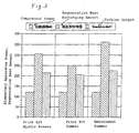
- Fig. 2 shows, in a cold/heat/electric power supply system using a regenerative gas turbine-driven generator of rated revolutions of 65,000 rpm and power generation output of 75 kW taken as an example in Table 1, comparison between the power generation terminal efficiency and power generation output (prior art in middle season) under the operation condition of ambient air temperature 15°C and relative humidity 30%, power generation terminal efficiency and power generation output under the operation condition of ambient air temperature 38°C and relative humidity 60% as a representative operation condition (prior art in summer), and power generation terminal efficiency and power generation output (present embodiment in summer) in the case where the humidification and cooling by cold water and the humidification by hot water according to the operation method of the present embodiment are used.
- Fig. 3 shows compressor power, regenerative heat exchanging amount and turbine output under each operation condition shown in Fig. 2.
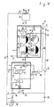
- Fig. 4 shows a cold/heat/electric power supply system of another embodiment of the present invention.
- the same constructions as in Fig. 1 are omitted to explain here, again.
- an intake air cooling device 32 for cooling the inlet air by heat exchange between cold water and the intake air is provided upstream of the spraying device 31 for intake air.
- the intake air cooling device 32 can supply inlet air cooling water 82 through an inlet air cooling device flow adjusting valve 36 in such a cases that excess cooling water is generated, an ambient temperature is particularly high in summer, and so on.
- Intake air cooling water 53 from the intake air cooling device 32 is recovered in an inlet of the feed water treating device 30 and circulates inside the cold/heat/electric power supply system.
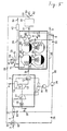
- Fig. 5 shows a cold/heat/electric power supply system of another embodiment of the present invention.
- a water recovery device 40 is added to the construction of the embodiment shown in Fig. 4. That is, in the present embodiment, the water recovery device 40 for recovering water in the absorption refrigerator exhaust gas 71 exhausted from the absorption refrigerator 2 (regenerator 21) is provided.
- the water recovery device 40 for recovering water in the absorption refrigerator exhaust gas 71 exhausted from the absorption refrigerator 2 (regenerator 21) is provided.
- water of several % of the intake air mass flow rate is consumed, so that in some cases a lot of water is included in the absorption refrigerator exhaust gas 71.
- the water recovery device 40 is provided for recovering the water from the absorption refrigerator exhaust gas 71 and effectively using the water as cleaning water or the like.
- a part of the intake air cooling water 53 led from the intake air cooling device 32 is branched by a water recovering flow adjusting valve 41 and sprayed as a water recovery device spray water 54 into the water recovery device 40, whereby direct heat exchange is effected and the water in the exhaust gas 71 is recovered.
- this recovering method it is possible to recover most of the water in the exhaust gas 71 without greatly increasing exhaust gas pressure loss, however, it also is possible to provide a water recovery device of heat exchanger type which uses the intake air cooling water 53 as a cooling water.
- the recovery water 55 recovered in the water recovery device 40 is subjected to dust removal or pH adjustment by a recovery water treatment device 42 and used as treatment-finished recovery water 56.
- the treatment-finished recovery water is suitable for use as cleaning water in various equipments.
- Fig. 6 shows a cold/heat/electric power supply system of another embodiment of the present invention.
- a heat accumulation type heat exchanger 39 is added to the construction of the embodiment shown in Fig. 5. That is, in the present embodiment, the heat accumulation type heat exchanger 39 is provided for causing the absorption refrigerator exhaust gas 71 exhausted from the absorption refrigerator 2 (regenerator 21) to heat-exchange with feed water 50.
- the heat exchanger exhaust gas 72 cooled in the heat accumulation type heat exchanger 39 is led to the water recovery device 40 to recover water in the exhaust gas. Further, the feed water heated through heat exchange with the absorption refrigerator exhaust gas 71 in the heat accumulation type heat exchanger 39 is supplied to hot water-utilizing apparatuses not shown as hot water 9.
- the absorption refrigerator exhaust gas 71 is still kept hot 120°C or more even after exhaust heat is recovered, and the heat of the exhaust gas 71 is wasted out of the system.
- the heat accumulation type heat exchanger 39 is provided in an exhaust path of the absorption refrigerator 2, the heat from exhaust heat of the absorption refrigerator exhaust gas 71 is recovered and accumulated, and hot water is generated by supplying the feed water 50 to the heat accumulation type heat exchanger 39 when a demand of hot water becomes large.
- recovery water 55 from the water recovering device 40 is subjected to dust removal or pH adjustment in the recovery water treatment device 42, and returned into a supply port of the feed water treatment device 30 as treatment-finished water 56, whereby an recirculation amount of water within the cold/heat/electric power supply equipment is increased and a feed water amount to the equipments is reduced.
- Fig. 7 shows a cold/heat/electric power supply system of another embodiment of the present invention.
- water is not supplied to the heat accumulation type heat exchanger as feed water 50 as in the construction of the embodiment shown in Fig. 6, but steam 10 is generated by using the hot water 9 generated in the absorption refrigerator 2.
- steam 10 is generated by using the hot water 9 generated in the absorption refrigerator 2.
- a heat/electricity ratio-variable operation which could not be effected by a conventional cold/heat/electric power supply system, that is, an operation which supplies excess heat to the regenerative gas turbine and improves the power generation output and power generation efficiency when excess cold/heat is generated in the absorption refrigerator can be carried out. Further, in the present embodiment, it is possible to improve, by using a part of the cold/heat generated in the absorption refrigerator, the characteristics that the power generation terminal output and power generation efficiency decreases due to an decrease in air density caused by rising in ambient temperature in summer.
Landscapes
- Engineering & Computer Science (AREA)
- Chemical & Material Sciences (AREA)
- Combustion & Propulsion (AREA)
- Mechanical Engineering (AREA)
- General Engineering & Computer Science (AREA)
- Physics & Mathematics (AREA)
- Thermal Sciences (AREA)
- Engine Equipment That Uses Special Cycles (AREA)
- Sorption Type Refrigeration Machines (AREA)
- Air Humidification (AREA)
Abstract
Description
| Items | Prior art | Embodiment | Effect(rel.%) | |
| Power generation output | (kW) | 75 | 90 | +20.2% |
| Power generation terminal efficiency | (%) | 29.9% | 32.8% | +9.6% |
| R.P.M. | (rpm) | 65000 | - | |
| Compression ratio | (-) | 4.0 | - | |
| Compressor efficiency | (%) | 79.0% | 79.5% | +0.5% |
| Turbine efficiency | (%) | 82.1% | 81.8% | -0.3% |
| Inlet air temp. | °C | 15.0 | 14.8 | - |
| Regenerator inlet temp. | °C | 191 | 144 | - |
| Combustor inlet temp. | °C | 616 | 610 | - |
| Turbine inlet temp. | °C | 930 | 950 | - |
| Exhaust gas temp. | °C | 256 | 204 | - |
| Compressor power | (kW) | 120 | 118 | -1.2% |
| Turbine output | (kW) | 214 | 232 | +8.2% |
| Regenerative heat exchanging amount | (kW) | 306 | 382 | +24.9% |
Claims (17)
- A heat and electric power supply system comprising:gas turbine equipment generating electric power;absorption refrigerating equipment recovering exhaust heat from said gas turbine equipment and generating thermal energy; andair cooling equipment, fluidly connected to said gas turbine and said absorption refrigerating equipment and cooling air for power generation in said gas turbine equipment with the thermal energy generated in said absorption refrigerating equipment.
- A heat and electric power supply system according to claim 1, wherein said thermal energy is used for cooling the air in the form of cold water and/or hot water.
- A heat and electric power supply system according to claim 2, wherein said cooling equipment comprises at least one of a spray device for spraying cold water from said absorption regenerating equipment onto air to be taken in a compressor of said gas turbine equipment, a humidifier for humidifying air at a delivery side of said compressor with hot water from said absorption regenerating equipment and an air cooling device disposed upstream of said spray device for cooling air to be taken in said compressor.
- A heat and electric power supply system according to claim 2, wherein a water recovering device is provided for recovering water contained in the exhaust gas having passed through said absorption refrigerating equipment.
- A heat and electric power supply system according to claim 2, wherein a heat accumulation type heat exchanger is provided for recovering and accumulating exhaust heat from exhaust gas having passed through said absorption refrigerating equipment.
- A heat and electric power supply system comprising:gas turbine equipment;absorption refrigerating equipment recovering exhaust heat from said gas turbine equipment and cooling or heating water; andan air cooling device leading water cooled in said absorption refrigerating equipment and cooling intake air of said gas turbine equipment.
- A heat and electric power supply system comprising:gas turbine equipment,absorption refrigerating equipment recovering exhaust heat of said gas turbine equipment and cooling or heating water, anda spraying device for intake air, spraying water cooled in said absorption refrigerating equipment onto intake air of said gas turbine equipment.
- A heat and electric power supply system comprising:gas turbine equipment having a compressor for compressing air, a combustor for burning compressed air and fuel, a turbine driven by combustion gas generated in said combustor, and a regenerative heat exchanger for heat-exchanging exhaust gas from said turbine and compressed air led to said combustor;absorption refrigerating equipment for recovering exhaust heat of said gas turbine equipment and cooling or heating water; anda humidifier spraying water heated in said absorption regenerating equipment onto the compressed air in said compressor.
- A heat and electric power supply system comprising:gas turbine equipment generating electric power by driving a generator;absorption refrigerating equipment recovering exhaust heat of said gas turbine equipment and generating cold water or hot water;an air cooling device cooling intake air of said gas turbine by using water generated in said absorption refrigerating equipment; anda humidifier spraying hot water generated in said absorption regenerating equipment and humidifying turbine intake air.
- A heat and electric power supply system according to claim 6, wherein said heat and electric power supply equipment is provided with a water recovering device for recovering water contained in the exhaust gas having passed through said absorption refrigerating equipment.
- A heat and electric power supply system according to claim 6, wherein said heat and electric power supply equipment is provided with a heat accumulation type heat exchanger for recovering and accumulating exhaust heat from exhaust gas having passed through said absorption refrigerating equipment.
- An operation method of a heat and electric power supply system comprising gas turbine equipment and absorption refrigerating equipment recovering exhaust heat of said gas turbine equipment and cooling or heating water, wherein in the case where cold or heat generated in said absorption refrigerating equipment have been excess, the excess heat is supplied to said gas turbine equipment.
- An operation method of a heat and electric power supply system comprising gas turbine equipment and absorption refrigerating equipment recovering exhaust heat of said gas turbine equipment and cooling or heating water, wherein intake air is cooled by spraying water cooled in said absorption refrigerating equipment onto the intake air of said gas turbine equipment.
- An operation method of a heat and electric power supply system comprising gas turbine equipment and absorption refrigerating equipment recovering exhaust heat of said gas turbine equipment and cooling or heating water, characterized in that compressed air of said gas turbine equipment is humidified by spraying thereon water heated in said absorption refrigerating equipment.
- An operation method of a heat and electric power supply system comprising gas turbine equipment driving a generator and generating electric power and absorption refrigerating equipment recovering exhaust heat of said gas turbine equipment and generating cold water or hot water, wherein gas turbine intake air is cooled by using cold water generated in said absorption refrigerating equipment and humidified by spraying thereon hot water generated in said absorption refrigerating equipment.
- An operation method of a heat and electric power supply system according to claim 12, wherein said operation method of heat and electric power supply equipment recovers and accumulates exhaust heat form exhaust gas passed through said absorption refrigerating equipment, and hot water is generated from the accumulated exhaust heat when the hot water is required.
- An operation method of a heat and electric power supply system according to claim 14, characterized in that said operation method of heat and electric power supply equipment a fuel flow rate to be supplied into a combustor of said gas turbine equipment is increased when humidification is effected.
Applications Claiming Priority (2)
| Application Number | Priority Date | Filing Date | Title |
|---|---|---|---|
| JP2000068612 | 2000-03-08 | ||
| JP2000068612A JP3750474B2 (en) | 2000-03-08 | 2000-03-08 | Cogeneration facility and operation method thereof |
Publications (3)
| Publication Number | Publication Date |
|---|---|
| EP1132595A2 true EP1132595A2 (en) | 2001-09-12 |
| EP1132595A3 EP1132595A3 (en) | 2005-03-02 |
| EP1132595B1 EP1132595B1 (en) | 2008-08-20 |
Family
ID=18587643
Family Applications (1)
| Application Number | Title | Priority Date | Filing Date |
|---|---|---|---|
| EP01105539A Expired - Lifetime EP1132595B1 (en) | 2000-03-08 | 2001-03-06 | Heat and electric power supply system and operation method thereof |
Country Status (5)
| Country | Link |
|---|---|
| US (2) | US6477852B2 (en) |
| EP (1) | EP1132595B1 (en) |
| JP (1) | JP3750474B2 (en) |
| CN (2) | CN1236202C (en) |
| DE (1) | DE60135403D1 (en) |
Cited By (3)
| Publication number | Priority date | Publication date | Assignee | Title |
|---|---|---|---|---|
| EP1191204A3 (en) * | 2000-09-26 | 2004-12-15 | Seibu Giken Co., Ltd. | A co-generation system and a dehumidification air-conditioner |
| WO2007054507A1 (en) * | 2005-11-08 | 2007-05-18 | Officine Termotecniche Fraccaro - O.T.F. S.R.L. | Device for heating, generating electric power, and cooling enclosed spaces |
| AT503533B1 (en) * | 2006-04-24 | 2009-02-15 | Falkinger Walter Ing | INCREASE IN USE BY HUMIDITY GAS FLOWS IN GAS TURBINES |
Families Citing this family (67)
| Publication number | Priority date | Publication date | Assignee | Title |
|---|---|---|---|---|
| US6981360B2 (en) * | 2001-04-09 | 2006-01-03 | Hitachi, Ltd. | Gas turbine power generator having humidifying and cooling means |
| GB2382848A (en) | 2001-12-06 | 2003-06-11 | Alstom | Gas turbine wet compression |
| GB2382847A (en) | 2001-12-06 | 2003-06-11 | Alstom | Gas turbine wet compression |
| EP1474595B1 (en) * | 2002-01-07 | 2007-03-14 | ALSTOM Technology Ltd | Method for operating a gas turbine group |
| AU2003266614A1 (en) * | 2002-09-26 | 2004-06-15 | Ebara Corporation | Absorption refrigerating machine |
| DE10256193A1 (en) | 2002-12-02 | 2004-06-09 | Alstom Technology Ltd | Method for controlling the liquid injection into an inflow channel of an engine or machine |
| JP4521855B2 (en) * | 2003-05-14 | 2010-08-11 | 荏原冷熱システム株式会社 | Absorption refrigerator |
| US7730633B2 (en) * | 2004-10-12 | 2010-06-08 | Pesco Inc. | Agricultural-product production with heat and moisture recovery and control |
| CN100402814C (en) * | 2005-01-20 | 2008-07-16 | 华南理工大学 | A flue gas low-temperature end heat utilization system for combined cooling, heating and power supply of natural gas |
| JP4648152B2 (en) * | 2005-10-14 | 2011-03-09 | 株式会社日立製作所 | Gas turbine system and method of operating gas turbine system |
| US8020397B2 (en) * | 2008-10-30 | 2011-09-20 | General Electric Company | Reduction of diluent nitrogen compressor power using vapor absorption chiller |
| US8370044B2 (en) * | 2009-06-26 | 2013-02-05 | General Electric Company | NOX compliant peak for gas turbine |
| WO2011011831A1 (en) * | 2009-07-31 | 2011-02-03 | The University Of Queensland | Thermal power plants |
| CN102278205A (en) * | 2010-06-13 | 2011-12-14 | 中国科学院工程热物理研究所 | Combined cycle method capable of being used for distributed air and fuel humidified gas turbine |
| US8544284B2 (en) * | 2010-06-25 | 2013-10-01 | Petrochina North China Petrochemical Company | Method and apparatus for waste heat recovery and absorption gases used as working fluid therein |
| US8474277B2 (en) * | 2010-07-13 | 2013-07-02 | General Electric Company | Compressor waste heat driven cooling system |
| CN101979129B (en) * | 2010-10-20 | 2012-10-17 | 南京大学 | Tail gas green management process for use in oxidization of benzene homologues in air |
| US20120102987A1 (en) * | 2010-10-29 | 2012-05-03 | Nuovo Pignone S.P.A. | Inlet Air Cooling and Moisture Removal Methods and Devices in Advance Adiabatic Compressed Air Energy Storage Systems |
| US20120102996A1 (en) * | 2010-10-29 | 2012-05-03 | General Electric Company | Rankine cycle integrated with absorption chiller |
| US8739522B2 (en) | 2010-10-29 | 2014-06-03 | Nuovo Pignone S.P.A. | Systems and methods for pre-heating compressed air in advanced adiabatic compressed air energy storage systems |
| DE102011118873A1 (en) * | 2011-11-18 | 2013-05-23 | Airbus Operations Gmbh | Vehicle with a cooling system for cooling and method for cooling in a vehicle |
| US9181876B2 (en) * | 2012-01-04 | 2015-11-10 | General Electric Company | Method and apparatus for operating a gas turbine engine |
| CN103256119A (en) * | 2012-06-19 | 2013-08-21 | 湖南大学 | Integration system for religion architecture |
| US9995218B2 (en) * | 2012-11-16 | 2018-06-12 | U.S. Well Services, LLC | Turbine chilling for oil field power generation |
| US11959371B2 (en) | 2012-11-16 | 2024-04-16 | Us Well Services, Llc | Suction and discharge lines for a dual hydraulic fracturing unit |
| US11476781B2 (en) | 2012-11-16 | 2022-10-18 | U.S. Well Services, LLC | Wireline power supply during electric powered fracturing operations |
| US10036238B2 (en) | 2012-11-16 | 2018-07-31 | U.S. Well Services, LLC | Cable management of electric powered hydraulic fracturing pump unit |
| US10526882B2 (en) | 2012-11-16 | 2020-01-07 | U.S. Well Services, LLC | Modular remote power generation and transmission for hydraulic fracturing system |
| US10407990B2 (en) | 2012-11-16 | 2019-09-10 | U.S. Well Services, LLC | Slide out pump stand for hydraulic fracturing equipment |
| US11449018B2 (en) | 2012-11-16 | 2022-09-20 | U.S. Well Services, LLC | System and method for parallel power and blackout protection for electric powered hydraulic fracturing |
| US9893500B2 (en) | 2012-11-16 | 2018-02-13 | U.S. Well Services, LLC | Switchgear load sharing for oil field equipment |
| US9745840B2 (en) | 2012-11-16 | 2017-08-29 | Us Well Services Llc | Electric powered pump down |
| US9650879B2 (en) | 2012-11-16 | 2017-05-16 | Us Well Services Llc | Torsional coupling for electric hydraulic fracturing fluid pumps |
| US9410410B2 (en) | 2012-11-16 | 2016-08-09 | Us Well Services Llc | System for pumping hydraulic fracturing fluid using electric pumps |
| US10119381B2 (en) | 2012-11-16 | 2018-11-06 | U.S. Well Services, LLC | System for reducing vibrations in a pressure pumping fleet |
| US9840901B2 (en) | 2012-11-16 | 2017-12-12 | U.S. Well Services, LLC | Remote monitoring for hydraulic fracturing equipment |
| US10232332B2 (en) | 2012-11-16 | 2019-03-19 | U.S. Well Services, Inc. | Independent control of auger and hopper assembly in electric blender system |
| US10020711B2 (en) | 2012-11-16 | 2018-07-10 | U.S. Well Services, LLC | System for fueling electric powered hydraulic fracturing equipment with multiple fuel sources |
| US9970278B2 (en) | 2012-11-16 | 2018-05-15 | U.S. Well Services, LLC | System for centralized monitoring and control of electric powered hydraulic fracturing fleet |
| US10254732B2 (en) | 2012-11-16 | 2019-04-09 | U.S. Well Services, Inc. | Monitoring and control of proppant storage from a datavan |
| DE102013215083A1 (en) * | 2013-08-01 | 2015-02-05 | Siemens Aktiengesellschaft | Flexible gas turbine power plant |
| CN103574982A (en) * | 2013-10-29 | 2014-02-12 | 清华大学 | Efficient cleaning and refrigerating system based on miniature gas turbine |
| US10808923B2 (en) * | 2014-06-16 | 2020-10-20 | Chevron U.S.A. Inc. | Multi-stage duct fired heat recovery steam generator and methods of use |
| US20150362173A1 (en) * | 2014-06-16 | 2015-12-17 | Chevron U.S.A. Inc. | Multi-Stage Duct Fired Heat Recovery Steam Generator and Methods of Use |
| CA2908276C (en) | 2014-10-14 | 2022-11-01 | Us Well Services Llc | Parallel power and blackout protection for electric hydraulic fracturing |
| CN107250511B (en) * | 2015-03-17 | 2020-01-07 | 三菱重工业株式会社 | Suction air cooling method, suction air cooling device implementing the method, waste heat recovery equipment and gas turbine plant equipped with the same |
| US12078110B2 (en) | 2015-11-20 | 2024-09-03 | Us Well Services, Llc | System for gas compression on electric hydraulic fracturing fleets |
| CN105715382B (en) * | 2016-01-21 | 2019-04-16 | 西安工程大学 | Evaporate the cooling reutilization system of gas turbine that cooling-absorption refrigeration combines |
| US12027831B2 (en) | 2016-04-15 | 2024-07-02 | U.S. Well Services, LLC | Switchgear load sharing for oil field equipment |
| US11181107B2 (en) | 2016-12-02 | 2021-11-23 | U.S. Well Services, LLC | Constant voltage power distribution system for use with an electric hydraulic fracturing system |
| US10280724B2 (en) | 2017-07-07 | 2019-05-07 | U.S. Well Services, Inc. | Hydraulic fracturing equipment with non-hydraulic power |
| US11067481B2 (en) | 2017-10-05 | 2021-07-20 | U.S. Well Services, LLC | Instrumented fracturing slurry flow system and method |
| CA3078879A1 (en) | 2017-10-13 | 2019-04-18 | U.S. Well Services, LLC | Automated fracturing system and method |
| AR114805A1 (en) | 2017-10-25 | 2020-10-21 | U S Well Services Llc | INTELLIGENT FRACTURING METHOD AND SYSTEM |
| WO2019113147A1 (en) | 2017-12-05 | 2019-06-13 | U.S. Well Services, Inc. | Multi-plunger pumps and associated drive systems |
| WO2019113153A1 (en) | 2017-12-05 | 2019-06-13 | U.S. Well Services, Inc. | High horsepower pumping configuration for an electric hydraulic fracturing system |
| AR114091A1 (en) | 2018-02-05 | 2020-07-22 | Us Well Services Inc | ELECTRICAL CHARGE MANAGEMENT IN MICROGRID |
| CA3097051A1 (en) | 2018-04-16 | 2019-10-24 | U.S. Well Services, LLC | Hybrid hydraulic fracturing fleet |
| CA3103490A1 (en) | 2018-06-15 | 2019-12-19 | U.S. Well Services, LLC | Integrated mobile power unit for hydraulic fracturing |
| CN109269149A (en) * | 2018-07-23 | 2019-01-25 | 南京航空航天大学 | Heat pump solution concentration cogeneration system and method |
| WO2020056258A1 (en) | 2018-09-14 | 2020-03-19 | U.S. Well Services, LLC | Riser assist for wellsites |
| CA3115669A1 (en) | 2018-10-09 | 2020-04-16 | U.S. Well Services, LLC | Modular switchgear system and power distribution for electric oilfield equipment |
| US11578577B2 (en) | 2019-03-20 | 2023-02-14 | U.S. Well Services, LLC | Oversized switchgear trailer for electric hydraulic fracturing |
| WO2020231483A1 (en) | 2019-05-13 | 2020-11-19 | U.S. Well Services, LLC | Encoderless vector control for vfd in hydraulic fracturing applications |
| WO2021022048A1 (en) | 2019-08-01 | 2021-02-04 | U.S. Well Services, LLC | High capacity power storage system for electric hydraulic fracturing |
| US11009162B1 (en) | 2019-12-27 | 2021-05-18 | U.S. Well Services, LLC | System and method for integrated flow supply line |
| US12601512B2 (en) * | 2023-09-06 | 2026-04-14 | Linyi university | Humidifying device and humidifying method for air-conditioning unit |
Family Cites Families (13)
| Publication number | Priority date | Publication date | Assignee | Title |
|---|---|---|---|---|
| US2548508A (en) * | 1946-03-05 | 1951-04-10 | Alfred S Wolfner | Thermal system |
| US3978661A (en) * | 1974-12-19 | 1976-09-07 | International Power Technology | Parallel-compound dual-fluid heat engine |
| US4380909A (en) * | 1981-07-17 | 1983-04-26 | Chevron Research Company | Method and apparatus for co-generation of electrical power and absorption-type heat pump air conditioning |
| US4773846A (en) * | 1985-07-30 | 1988-09-27 | Michael Munk | Combustion system and method with fog injection and heat exchange |
| US4987750A (en) * | 1986-07-08 | 1991-01-29 | Gershon Meckler | Air conditioning apparatus |
| US4942734A (en) * | 1989-03-20 | 1990-07-24 | Kryos Energy Inc. | Cogeneration of electricity and liquid carbon dioxide by combustion of methane-rich gas |
| US5203161A (en) * | 1990-10-30 | 1993-04-20 | Lehto John M | Method and arrangement for cooling air to gas turbine inlet |
| US5353585A (en) * | 1992-03-03 | 1994-10-11 | Michael Munk | Controlled fog injection for internal combustion system |
| JP2877098B2 (en) * | 1995-12-28 | 1999-03-31 | 株式会社日立製作所 | Gas turbines, combined cycle plants and compressors |
| JP3769347B2 (en) * | 1997-03-19 | 2006-04-26 | 株式会社 日立インダストリイズ | Gas turbine intake air cooling system |
| US6389799B1 (en) * | 1997-04-22 | 2002-05-21 | Hitachi, Ltd. | Gas turbine Installation |
| US6107693A (en) * | 1997-09-19 | 2000-08-22 | Solo Energy Corporation | Self-contained energy center for producing mechanical, electrical, and heat energy |
| JPH11324710A (en) * | 1998-05-20 | 1999-11-26 | Hitachi Ltd | Gas turbine power plant |
-
2000
- 2000-03-08 JP JP2000068612A patent/JP3750474B2/en not_active Expired - Fee Related
-
2001
- 2001-03-06 US US09/799,056 patent/US6477852B2/en not_active Expired - Lifetime
- 2001-03-06 DE DE60135403T patent/DE60135403D1/en not_active Expired - Fee Related
- 2001-03-06 EP EP01105539A patent/EP1132595B1/en not_active Expired - Lifetime
- 2001-03-08 CN CNB011170611A patent/CN1236202C/en not_active Expired - Fee Related
- 2001-03-08 CN CNB2005100648617A patent/CN100429387C/en not_active Expired - Fee Related
-
2002
- 2002-09-20 US US10/247,344 patent/US6769266B2/en not_active Expired - Fee Related
Non-Patent Citations (1)
| Title |
|---|
| "CLEAN ENERGY", vol. 6, JAPAN INDUSTRY, pages: 1 - 36 |
Cited By (4)
| Publication number | Priority date | Publication date | Assignee | Title |
|---|---|---|---|---|
| EP1191204A3 (en) * | 2000-09-26 | 2004-12-15 | Seibu Giken Co., Ltd. | A co-generation system and a dehumidification air-conditioner |
| WO2007054507A1 (en) * | 2005-11-08 | 2007-05-18 | Officine Termotecniche Fraccaro - O.T.F. S.R.L. | Device for heating, generating electric power, and cooling enclosed spaces |
| US8132738B2 (en) * | 2005-11-08 | 2012-03-13 | Officine Termotecniche Fraccaro -O.T.F. S.R.L. | Device for heating, generating electric power, and cooling enclosed spaces |
| AT503533B1 (en) * | 2006-04-24 | 2009-02-15 | Falkinger Walter Ing | INCREASE IN USE BY HUMIDITY GAS FLOWS IN GAS TURBINES |
Also Published As
| Publication number | Publication date |
|---|---|
| US6477852B2 (en) | 2002-11-12 |
| CN100429387C (en) | 2008-10-29 |
| EP1132595A3 (en) | 2005-03-02 |
| CN1236202C (en) | 2006-01-11 |
| CN1693686A (en) | 2005-11-09 |
| CN1312430A (en) | 2001-09-12 |
| US20010042381A1 (en) | 2001-11-22 |
| DE60135403D1 (en) | 2008-10-02 |
| US6769266B2 (en) | 2004-08-03 |
| EP1132595B1 (en) | 2008-08-20 |
| JP2001254632A (en) | 2001-09-21 |
| US20030019229A1 (en) | 2003-01-30 |
| JP3750474B2 (en) | 2006-03-01 |
Similar Documents
| Publication | Publication Date | Title |
|---|---|---|
| US6477852B2 (en) | Heat and electric power supply system and operation method thereof | |
| EP0959235B1 (en) | Gas turbine power plant | |
| JP2851794B2 (en) | Combustion air precooling system for gas turbine | |
| US6718771B1 (en) | Gas turbine operative at high ambient temperatures | |
| US7007453B2 (en) | Power system and method | |
| CA1331522C (en) | Apparatus and method for optimizing the air inlet temperature of gas turbines | |
| CN101663473B (en) | Cooling, heating and power integrated system | |
| US5758511A (en) | Desiccant multi-duel hot air/water air conditioning system | |
| US4936109A (en) | System and method for reducing gas compressor energy requirements | |
| US6422019B1 (en) | Apparatus for augmenting power produced from gas turbines | |
| JPH05133244A (en) | Air precooling method and air precooling device | |
| JPH07166888A (en) | Method and equipment for increasing power generated from gas turbine | |
| US20110173947A1 (en) | System and method for gas turbine power augmentation | |
| US6708517B1 (en) | Heat pump | |
| JP2003161164A (en) | Combined cycle power plant | |
| JP2005315127A (en) | Gas turbine | |
| CN102278205A (en) | Combined cycle method capable of being used for distributed air and fuel humidified gas turbine | |
| JPH06235332A (en) | Method for evaporating liquefied natural gas fuel for gas turbine and method for improving gas turbine performance | |
| CN116539320A (en) | Humidification gas turbine circulation test system | |
| EP0535106B1 (en) | Method of transferring heat from a low to a higher temperature | |
| JP3924489B2 (en) | Thermoelectric supply system | |
| JP2001115855A (en) | Gas turbine system | |
| WO2001018372A1 (en) | Gas turbine operative at high ambient temperatures | |
| JP2002267276A (en) | Solar cooling system | |
| HK1141854B (en) | Integrated cooling, heating, and power systems |
Legal Events
| Date | Code | Title | Description |
|---|---|---|---|
| PUAI | Public reference made under article 153(3) epc to a published international application that has entered the european phase |
Free format text: ORIGINAL CODE: 0009012 |
|
| AK | Designated contracting states |
Kind code of ref document: A2 Designated state(s): AT BE CH CY DE DK ES FI FR GB GR IE IT LI LU MC NL PT SE TR |
|
| AX | Request for extension of the european patent |
Free format text: AL;LT;LV;MK;RO;SI |
|
| PUAL | Search report despatched |
Free format text: ORIGINAL CODE: 0009013 |
|
| AK | Designated contracting states |
Kind code of ref document: A3 Designated state(s): AT BE CH CY DE DK ES FI FR GB GR IE IT LI LU MC NL PT SE TR |
|
| AX | Request for extension of the european patent |
Extension state: AL LT LV MK RO SI |
|
| 17P | Request for examination filed |
Effective date: 20050831 |
|
| AKX | Designation fees paid |
Designated state(s): DE FR GB |
|
| GRAP | Despatch of communication of intention to grant a patent |
Free format text: ORIGINAL CODE: EPIDOSNIGR1 |
|
| GRAS | Grant fee paid |
Free format text: ORIGINAL CODE: EPIDOSNIGR3 |
|
| GRAA | (expected) grant |
Free format text: ORIGINAL CODE: 0009210 |
|
| AK | Designated contracting states |
Kind code of ref document: B1 Designated state(s): DE FR GB |
|
| REG | Reference to a national code |
Ref country code: GB Ref legal event code: FG4D |
|
| REF | Corresponds to: |
Ref document number: 60135403 Country of ref document: DE Date of ref document: 20081002 Kind code of ref document: P |
|
| PLBE | No opposition filed within time limit |
Free format text: ORIGINAL CODE: 0009261 |
|
| STAA | Information on the status of an ep patent application or granted ep patent |
Free format text: STATUS: NO OPPOSITION FILED WITHIN TIME LIMIT |
|
| PGFP | Annual fee paid to national office [announced via postgrant information from national office to epo] |
Ref country code: GB Payment date: 20090220 Year of fee payment: 9 |
|
| 26N | No opposition filed |
Effective date: 20090525 |
|
| PGFP | Annual fee paid to national office [announced via postgrant information from national office to epo] |
Ref country code: DE Payment date: 20090519 Year of fee payment: 9 |
|
| PGFP | Annual fee paid to national office [announced via postgrant information from national office to epo] |
Ref country code: FR Payment date: 20090128 Year of fee payment: 9 |
|
| GBPC | Gb: european patent ceased through non-payment of renewal fee |
Effective date: 20100306 |
|
| REG | Reference to a national code |
Ref country code: FR Ref legal event code: ST Effective date: 20101130 |
|
| PG25 | Lapsed in a contracting state [announced via postgrant information from national office to epo] |
Ref country code: FR Free format text: LAPSE BECAUSE OF NON-PAYMENT OF DUE FEES Effective date: 20100331 |
|
| PG25 | Lapsed in a contracting state [announced via postgrant information from national office to epo] |
Ref country code: DE Free format text: LAPSE BECAUSE OF NON-PAYMENT OF DUE FEES Effective date: 20101001 |
|
| PG25 | Lapsed in a contracting state [announced via postgrant information from national office to epo] |
Ref country code: GB Free format text: LAPSE BECAUSE OF NON-PAYMENT OF DUE FEES Effective date: 20100306 |