EP1132282A2 - Improved structure of rear portion of automotive vehicle body - Google Patents
Improved structure of rear portion of automotive vehicle body Download PDFInfo
- Publication number
- EP1132282A2 EP1132282A2 EP01302159A EP01302159A EP1132282A2 EP 1132282 A2 EP1132282 A2 EP 1132282A2 EP 01302159 A EP01302159 A EP 01302159A EP 01302159 A EP01302159 A EP 01302159A EP 1132282 A2 EP1132282 A2 EP 1132282A2
- Authority
- EP
- European Patent Office
- Prior art keywords
- structural
- rear body
- structural element
- body structural
- inners
- Prior art date
- Legal status (The legal status is an assumption and is not a legal conclusion. Google has not performed a legal analysis and makes no representation as to the accuracy of the status listed.)
- Granted
Links
- 238000005266 casting Methods 0.000 claims abstract description 3
- 230000001681 protective effect Effects 0.000 abstract description 3
- 230000007423 decrease Effects 0.000 description 3
- 230000002787 reinforcement Effects 0.000 description 3
- 239000011324 bead Substances 0.000 description 2
- 230000002708 enhancing effect Effects 0.000 description 2
- 238000005304 joining Methods 0.000 description 2
- 238000004519 manufacturing process Methods 0.000 description 2
- 230000004048 modification Effects 0.000 description 2
- 238000012986 modification Methods 0.000 description 2
- 229910000838 Al alloy Inorganic materials 0.000 description 1
- 238000010521 absorption reaction Methods 0.000 description 1
- 230000005540 biological transmission Effects 0.000 description 1
- 239000012141 concentrate Substances 0.000 description 1
- 230000003247 decreasing effect Effects 0.000 description 1
- 230000001939 inductive effect Effects 0.000 description 1
- 239000007769 metal material Substances 0.000 description 1
- 238000003466 welding Methods 0.000 description 1
Images




Classifications
-
- B—PERFORMING OPERATIONS; TRANSPORTING
- B62—LAND VEHICLES FOR TRAVELLING OTHERWISE THAN ON RAILS
- B62D—MOTOR VEHICLES; TRAILERS
- B62D25/00—Superstructure or monocoque structure sub-units; Parts or details thereof not otherwise provided for
- B62D25/08—Front or rear portions
Definitions
- the present invention relates generally to the structure of a rear portion of a vehicle body for an automotive vehicle.
- Japanese Patent First Publication No. 10-129533 shows a rear body of a vehicle in which a reinforcement member is installed diagonally to connect an end portion of each rear side-member to an end portion of a rear cross-member across a joint of them to increase the torsional rigidity of the rear portion of the vehicle body, thereby distributing the energy of an impact force upon occurrence of a rear-end collision of the vehicle to the rear side-members, the rear cross-member, and rear wheel housing so as to define an impact absorbing structural portion occupying a portion of the vehicle body in front of the reinforcement members and a vehicle body deformable portion occupying the remaining portion of the vehicle body on the rear side of the reinforcement members.
- the above vehicle body structure is designed to absorb the energy of an impact force produced by a rear-end collision of the vehicle through structural members such as the rear side-members arranged at a lower portion of the vehicle body and thus encounters the drawback that it is very difficult to distribute the energy of the impact force up to an upper portion of the vehicle body effectively. Further, since the lower portion of the vehicle body absorbs the energy of the impact force as a whole, the need may arise for reconditioning or replacing the whole rear portion of the vehicle body.
- a rear body for an automotive vehicle which comprises: a front body structural element defining a front portion of the rear body; and a rear body structural element.
- the rear body structural element is joined to the front body structural element to define a rear portion of the rear body and has a rigidity smaller than that of the front body structural element.
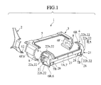
- FIG. 1 there is shown an improved structure of a rear portion of an automotive vehicle body according to the invention.
- a rear body 1 is made of a lightweight metallic material such as aluminum alloy and has three parts: a front body structural element 2, an intermediate body structural element 3, and a rear body structural element 4 which are arrayed longitudinally of a vehicle body.
- the front body structural element 2 forms body side inners.
- the intermediate body structural element 3 includes a rear parcel shelf or cross-member 5 and a front portion 6F of each of two rear fender inners 6.
- the rear body structural element 4 includes a rear portion 6R of each of the rear fender inners 6 and a rear end panel 7.
- the front portions 6F and the rear portions 6R of the rear fender inners 6 will be referred to as a rear fender inner of the intermediate body structural element 3 and a rear fender inner of the rear body structural element 4, respectively.
- the rear body structural element 4 is lower in rigidity than the intermediate body structural element 3.
- the rear body structural element 4 is smaller in lateral cross-section than the intermediate body structural element 3.
- the rear body structural element 3 decreases gradually in lateral cross-section toward the rear end panel 7.
- the wall thickness of the rear body 1 increases from the rear body structural element 4 to the intermediate body structural element 3 and to the front body structural element 2, thereby increasing the rigidity of the rear body 1 gradually from the rear body structural element 4 to the front body structural element 2.
- the intermediate body structural element 3 has flanges 8 formed on the rear fender inners 6F.
- the rear body structural element 4 has flanges 9 formed on the rear fender inner 6R.
- the intermediate body structural element 3 and the rear body structural element 4 are joined to each other, as clearly shown in Fig. 3, by connecting the flanges 8 and 9 together through fastening members 10 such as rivets.
- the rear body structural element 4 is, as discussed above, smaller in lateral cross-section thereof than the intermediate body structural element 3.
- the flange 9 of the rear body structural element 4 is bent outward, while the flange 8 of the intermediate body structural element 3 is bent inward so that the flanges 8 and 9 may be brought into surface-to-surface contact.
- the intermediate body structural element 3 has ribs 11 formed on an inner wall of each of the rear fender inners 6F in contact with the flange 8 for transferring the impact acting on the rear body structural element 4 upon occurrence of a rear-end collision of the vehicle into an in-plane pressure exerted on the rear fender inner 6F.
- the intermediate body structural element 3 is, as clearly shown in Fig. 3, lapped partially in the front body structural element 2 and welded as indicated at W.
- the intermediate body structural element 3 is, as described above, smaller in wall thickness than the front body structural element 2 as a whole, but it has a thick end portion welded to the front body structural element 2 whose thickness is substantially equal to that of the front body structural element 2 for increasing the strength of connection between the intermediate body structural element 3 and the front body structural element 2.
- the front body structural element 2 has a plurality of ribs 12 formed integrally on an inner wall thereof which are in contact with the end of the intermediate body structural element 3 when the front body structural element 2 and the intermediate body structural element 3 are joined together, thereby transferring the collision impact transmitted from the intermediate body structural element 3 into an in-plane pressure acting on the front body structural element 2.
- the ribs 12 also work as stops which assist in positioning the front body structural element 2 longitudinally when joined to the intermediate body structural element 3.
- the rear body structural element 4 has formed in each of the rear fender inners 6R an easy-to-deform portion 21 which serves to facilitate collapse of the rear fender inner 6R in response to input of the impact produced by the rear-end collision of the vehicle.
- Each of the easy-to-deform portions 21 has V-shaped grooves 22 formed at given vertical intervals in an outer wall of one of the rear fender inner 6R bulging outward along a vertical car line.
- the grooves 22 extend longitudinally of the vehicle body and define ridges 23 on an inner wall of each of the rear fender inners6R.
- Each of the ridges 23 has a notch 24 formed in the longitudinal center thereof which serves to induce a corresponding one of the rear fender inners 6R to be collapsed easily so that the grooves 22 may be opened vertically when the vehicle is involved in a rear-end collision.
- the grooves 22 extend from the flange 9 of each of the rear fender inners 6R to the rear end of the rear fender inner 6R.
- Each of the notches 24 also serves as a step with which an end of an ejector pin (not shown) engages when the rear body structural element 4 is withdrawn (in a longitudinal direction of the vehicle body in the drawing) from a mold in a casting process.
- Two of the notches 24 which are, as indicated at 24a in Fig. 3, formed in the ridges 23 of each of the rear fender inners 6R located outward in a widthwise direction of the vehicle body are offset rearward of two of the notches 24, as indicated at 24b, located inward in the widthwise direction of the vehicle body.
- the rear end panel 7 has an upper half which extends in the widthwise direction of the vehicle body and bulges outward to define a trunk lid receiver 7A and a lower half which bulges inward and has side member mounts 7B formed on ends thereof.
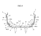
- the trunk lid receiver 7A has, as clearly shown in Fig. 2, a load transmitting means 25 formed over a length thereof which works to transmit a rear-end collision impact force to the rear fender inners 6.
- the load transmitting means 25 is made up of diagonal ribs 25a and vertical ribs 25b provided within a recess formed in an inner wall of the trunk lid receiver 7A.
- the diagonal ribs 25a extend in a wave form within the trunk lid receiver 7A between the side member mounts 7B.
- the vertical ribs 25b are arranged outside the diagonal ribs 25a.
- the trunk lid receiver 7A has formed in a central portion of an upper surface thereof a striker receiver 26 into which a striker of a lock mechanism of a trunk (not shown) is fitted.
- the trunk lid receiver 7A also has an upright bead 27 (which is formed by bulging a central portion of a rear wall thereof inward, serving as a fragile portion).
- each of the side member mounts 7B has, as shown in Fig. 1, a vertical rib 28 which is formed on the outside wall thereof and extends up to an outer bottom wall of the trunk lid receiver 7A for increasing the rigidity thereof.
- the rear body 1 is made up of three cast parts: the front body structural element 2, the intermediate body structural element 3, and the rear body structural element 4 which are arrayed longitudinally of the vehicle body.
- the wall thickness of the rear body 1 increases from the rear body structural element 4 to the intermediate body structural element 3 and to the front body structural element 2, and the rear body structural element 4 decreases in lateral cross-section gradually, thereby increasing the rigidity of the rear body 1 from the rear body structural element 4 to the front body structural element 2.
- the rear body 1 absorbs the energy of collision impact as a whole as well as the absorption by lower portions of the rear side members.
- the rigidity of the rear body 1, as described above, increases from the rear body structural element 4 to the intermediate body structural element 3 and to the front body structural element 2, that is, as approaching the vehicle cabin.
- the rear body 1 is so designed as to have the greatest resistance to the collapse caused by a rear-end collision in the front body structural element 2 and induce the rear body structural element 4 to be collapsed easily, thereby minimizing the amount of collapse of the front body structural element 2 and the intermediate body structural element 3 to provide a protective structural area as great as possible to the front of the rear body 1 close to the vehicle cabin.
- the joining of the rear body structural element 4 and the intermediate body structural element 3 using the flanges 9 and 8 increases the degree of transmission of the rear-end collision impact force from the rear body structural element 4 to the front body structural element 2 through the intermediate body structural element 3 and also ensures a higher resistance of the rear body structural element 4 to the collapse.
- the rear body structural element 4, as described above, has formed in each of the rear fender inners 6R the easy-to-deform portion 21 serving to facilitate a collapse of the rear fender inner 6R in response to an impact force produced by the rear-end collision of the vehicle.
- the trunk lid receiver 7A of the rear end panel 7 has the load transmitting means 25 which works to transmit the rear-end collision impact force to the rear fender inners 6.
- the rear-end collision impact force is, thus, transmitted to the right and left rear fender inners 6R effectively to induce the collapse of the rear fender inners 6R from the easy-to-deform portions 21, thereby resulting in collapse of the rear body structural element 4 in an optimum deformation mode.
- Each of the easy-to-deform portions 21 has the V-shaped grooves 22 extending in parallel at a given vertical interval and the notches 24 formed in the central portions of the ridges 23 defined by the grooves 22 so that the rear fender inners 6R may be bent inward at the notches 24 upon input of the rear-end collision impact force, causing the grooves 23 to be opened vertically.
- the collapse of each of the rear fender inners 6R includes, as shown in Fig. 4, the vertical deformation of the grooves 22 and an outward bulge thereof, thereby absorbing the energy of the rear-end collision impact effectively.
- the notches 24a which are formed in the ridges 23 defined by the grooves 22a located outward of the vehicle body are, as described above, offset rearward of the notches 24b formed on the ridges 23 defined by the grooves 22b located inward of the vehicle body, thereby causing an outward bulging portion of each of the rear fender inners 6R which is difficult to deform to be collapsed earlier so that the rear fender inners 6R are collapsed in a desired mode.
- the longitudinal offset of the notches 24a and 24b avoids the interference of the vertical deformation of the grooves 22a with that of the grooves 22b, thereby enhancing the efficiency in absorbing the energy of collision impact.
- Fig. 6 shows a collapse of the rear end panel 7 when the vehicle is involved in the so-called offset rear-end collision in which the impact force F is applied to a half of the rear end panel 7 from a perpendicular direction.
- the impact force F acts only on one of the rear fender inners 6R located on the collision side, but the bead 27 extending vertically in the central portion of the rear end panel 7 works as a fragile portion to induce the rear end panel 7 to be bent at the center thereof, so that the impact force F is transmitted as the moment of force to the other rear fender inner 6R on the non-collision side.
- Fig. 8 shows the rear body 1 according to a second embodiment of the invention, which is different from the first embodiment in a connection of the front body structural element 2 and the intermediate body structural element 3. Other arrangement are identical, and explanation thereof in detail will be omitted here.
- the front body structural element 2 has a flange 14 bent inward.
- the intermediate body structural element 3 has a flange 15 bent outward.
- the front body structural element 2 and the intermediate body structural element 3 are jointed by welding the flange 15 on the flange 14, as indicated at W.
- a plurality of ribs 16 are formed on an inner comer of the flange 14 to transfer an impact force produced by a rear-end collision of the vehicle into an in-plane pressure acting on the front body structural element 2.
- Fig. 9 shows the rear body 1 according to a third embodiment of the invention, which is different from the first embodiment in a connection of the intermediate body structural element 3 and the rear body structural element 4. Other arrangement are identical, and explanation thereof in detail will be omitted here.
- the rear body structural element 4 is lapped at an end portion thereof over the intermediate body structural element 3 and joined together by fastening members 10 such as rivets.
- a plurality of ribs 17 are formed integrally on an inner wall of the intermediate body structural element 3 which are in contact with an end of the rear body structural element 4 when the intermediate body structural element 3 is joined to the rear body structural element 4 for transferring a rear-end collision impact force exerted on the rear body structural element 4 into an in-plane pressure acting on the intermediate body structural element 3.
- the ribs 17 also serve as stops for positioning the rear body structural element 4 when fitted into the intermediate body structural element 3.
- Figs. 10 and 11 show a modification of the easy-to-deform portion 21 of each of the rear fender inners 6R of the rear body structural element 4.
- the easy-to-deform portion 21 is made of a wall which is corrugated to define V-shaped troughs 22 and peaks 32 extending horizontally and which bulges, like the first embodiment, outward as a whole along a vertical car line of the rear fender inner 6R.
- the V-shaped troughs 22 have substantially the same length as that of the grooves 22 in the first embodiment.
- Each of the peaks 32 has a notch 34 formed in a central portion of the ridge 33 for inducing the rear fender inner 6R to be collapsed easily at the notches 34 when a rear-end collision impact force F, as shown in Fig. 11, is applied to the rear end panel 7.
- Two of the notches 34, as indicated at 34a, which are formed in the peaks 32a located outward in the widthwise direction of the vehicle body are offset, like the first embodiment, rearward of two of the notches 34, as indicated at 34b, located inward in the widthwise direction of the vehicle body, thereby causing an outmost portion of each of the rear fender inners 6R to be collapsed earlier so that the rear fender inner 6R is collapsed in a desired mode.
- the longitudinal offset of the notches 34a and 34b also serves to avoid the interference of inward bends of the outer peaks 32a at the notches 34a with those of the inner peaks 32b at the notches 34b, thereby enhancing the efficiency in absorbing the energy of collision impact.
- Notches may also be formed in the inner wall (i.e., the troughs 22) of the rear fender inners 6R.
- the structure of the rear body 1 is so designed as to facilitate the ease of collapse of a rear portion thereof (i.e., the rear body structural element 4) for absorbing the energy of a collision impact force acting on the rear of the vehicle body in an ideal mode to provide an occupant protective area on the front side of the rear body 1.
- the rear body 1 is fabricated from three cast parts: the front body structural element 2, the intermediate body structural element 3, and the rear body structural element 4, thus decreasing the number of parts and production processes greatly as compared with a conventional structure of a rear body made by assembling many panel members.
- the assembly of the vehicle body may be accomplished by preparing a subassembly made up of the body structural elements 2, 3, and 4 and then joining it to a front body, thereby facilitating the ease of automatic assembly of the vehicle body and resulting in a decrease in manufacturing cost.
- the rear body 1 may alternatively be made up of two separate cast parts: one being an one-piece structural member including the front body structural element 2 and the intermediate body structural element 3 integrally and the other being the rear body structural element 4.
Landscapes
- Engineering & Computer Science (AREA)
- Chemical & Material Sciences (AREA)
- Combustion & Propulsion (AREA)
- Transportation (AREA)
- Mechanical Engineering (AREA)
- Body Structure For Vehicles (AREA)
Abstract
Description
The rear body
Claims (17)
- A rear body for an automotive vehicle comprising:a front cast body-structural-element (2) constituting a front portion of the rear body; anda rear cast body-structural-element (4) constituting a rear portion of the rear body, the rear body-structural-element (4) being joined to the front body-structural-element (2) and having a rigidity smaller than that of the front body-structural-element (2).
- A rear body as claimed in claim 1, including an intermediate body-structural-element (3) joined between the front body-structural-element (2) and the rear body-structural-element (4), and wherein the front body-structural-element (2) defines body side inners, the intermediate body-structural-element (3) includes a rear parcel cross-member (5) and front portions (6F) of rear fender inners (6), and the rear body-structural-element (4) includes rear portions (6R) of the rear fender inners (6) and a rear end panel (7), and wherein the rigidity of the rear body increases gradually from the rear body-structural-element (4) to the front body-structural-element (2) through the intermediate body-structural-element (3).
- A rear body as claimed in claim 2, wherein the intermediate body-structural-element (3) has flanges (8) on the front portions (6F) of the rear fender inners (6), the rear body-structural-element (4) has flanges (9) on the rear portions (6R) of the rear fender inners (6), and the intermediate body-structural-element (3) and the rear body-structural-element (4) are joined together by connecting the flanges (8,9) using fastening means (10).
- A rear body as claimed in claim 2 or 3, wherein the rear body-structural-element (4) has provided in the front portions (6F) of the rear fender inners (6) easy-to-deform portions (21) which serve to facilitate collapse of the front portions (6F) of the rear fender inners (6) in response to input of an impact force produced by a rear-end collision of the vehicle.
- A rear body as claimed in claim 4, wherein each easy-to-deform portion (21) has a wall of the front portion (6F) of a rear fender inner (6) which bulges outward along a vertical line and is waved to define troughs (22) and ridges (23) extending longitudinally of the rear body, each ridge (23) having in a middle region of its length a fragile portion (24) which serves to induce the front portion (6F) of the rear fender inner to be bent thereat in an inward or outward direction in response to input of an impact force produced by a rear-end collision of the vehicle.
- A rear body as claimed in claim 5, wherein at least one fragile portion (24a) located outward of the rear body is offset rearward of at least one fragile portion (24b) located inward of the rear body.
- A rear body as claimed in any of claims 4 to 6, wherein the rear end panel (7) has a load transmitting portion extending in a widthwise direction of the rear body for transmitting an impact force produced by a rear-end collision of the vehicle to the rear fender inners (6).
- A rear body as claimed in claim 7, wherein the rear end panel (7) has a vertically extending fragile portion (27) formed in a middle region thereof in a widthwise direction of the rear body.
- A rear body as claimed in claim 1, wherein the rear body-structural-element (4) has an energy absorbing portion for absorbing energy of a collision impact.
- A rear body as claimed in claim 9, wherein the energy absorbing portion comprises an easy-to-deform portion.
- A rear body as claimed in claim 10, wherein the easy-to-deform portion comprises a fragile portion between rigid portions.
- A rear body as claimed in claim 10, wherein fragile portions are disposed on a rear fender inner and a rear end panel.
- A rear body as claimed in claim 11, wherein the fragile portion comprises a notch and the rigid portion comprises a ridge.
- A rear body as claimed in claim 11, wherein the fragile portion is capable of serving as a pin engage portion when the rear body-structural-element (4) is withdrawn from a mold in a casting process.
- A rear body as claimed in claim 1, wherein the rigidity is changed by changing wall thickness.
- A rear body as claimed in claim 3, further comprising ridges connecting with at least one of the flanges (8,9).
- A rear body for an automotive vehicle, comprising:front body structural element means for defining a front portion of the rear body, andrear body structural element means for defining a rear portion of the rear body,said rear body structural element means being joined to said front body structural element means and having a rigidity smaller than that of said front body structural element means.
Applications Claiming Priority (2)
| Application Number | Priority Date | Filing Date | Title |
|---|---|---|---|
| JP2000066534 | 2000-03-10 | ||
| JP2000066534A JP3436232B2 (en) | 2000-03-10 | 2000-03-10 | Car body rear structure |
Publications (3)
| Publication Number | Publication Date |
|---|---|
| EP1132282A2 true EP1132282A2 (en) | 2001-09-12 |
| EP1132282A3 EP1132282A3 (en) | 2002-11-20 |
| EP1132282B1 EP1132282B1 (en) | 2004-09-15 |
Family
ID=18585883
Family Applications (1)
| Application Number | Title | Priority Date | Filing Date |
|---|---|---|---|
| EP01302159A Expired - Lifetime EP1132282B1 (en) | 2000-03-10 | 2001-03-09 | Improved structure of rear portion of automotive vehicle body |
Country Status (4)
| Country | Link |
|---|---|
| US (1) | US6450567B2 (en) |
| EP (1) | EP1132282B1 (en) |
| JP (1) | JP3436232B2 (en) |
| DE (1) | DE60105465T2 (en) |
Cited By (5)
| Publication number | Priority date | Publication date | Assignee | Title |
|---|---|---|---|---|
| EP1134148A3 (en) * | 2000-03-15 | 2003-01-22 | Nissan Motor Company, Limited | Frame structure for vehicle |
| FR2922182A1 (en) * | 2007-10-12 | 2009-04-17 | Peugeot Citroen Automobiles Sa | Motor vehicle, has lower plate to close latching tab passage opening, and to form support surface for sealing ring when sealing ring is applied in opening, where latching tab is connected to rear panel lining by electric welding point |
| WO2013082261A1 (en) * | 2011-12-02 | 2013-06-06 | Shape Corp. | Vehicle with body-mounted energy absorber apparatus |
| CN105966246A (en) * | 2016-06-22 | 2016-09-28 | 安徽岳塑汽车工业股份有限公司 | Wide left-arranged instrument desk |
| US9994272B2 (en) | 2016-08-29 | 2018-06-12 | Shinji Marui | Bicycle saddle |
Families Citing this family (26)
| Publication number | Priority date | Publication date | Assignee | Title |
|---|---|---|---|---|
| FR2805514B1 (en) * | 2000-02-24 | 2002-05-31 | Plastic Omnium Cie | REAR MODULE FOR MOTOR VEHICLE |
| DE10060784B4 (en) * | 2000-12-07 | 2006-03-16 | Ise Innomotive Systems Europe Gmbh | Rear module for passenger vehicles |
| US6883858B2 (en) * | 2002-09-10 | 2005-04-26 | L & L Products, Inc. | Structural reinforcement member and method of use therefor |
| JP5092323B2 (en) * | 2006-09-08 | 2012-12-05 | 株式会社日立製作所 | Rail vehicle |
| US7677649B2 (en) * | 2007-01-11 | 2010-03-16 | Ford Motor Company | Vehicle having an interlocking floor assembly |
| US7849601B2 (en) * | 2007-01-11 | 2010-12-14 | Ford Motor Company | Method of manufacturing a vehicle |
| US8038205B2 (en) * | 2007-01-11 | 2011-10-18 | Ford Motor Company | Vehicle having a passenger compartment body structure |
| US8177277B2 (en) * | 2007-01-11 | 2012-05-15 | Ford Motor Company | Vehicle having a body panel |
| US7703841B2 (en) * | 2007-01-11 | 2010-04-27 | Ford Motor Company | Vehicle body assembly |
| US7850226B2 (en) * | 2007-01-11 | 2010-12-14 | Ford Motor Company | Vehicle having a passenger compartment body structure |
| US7594690B2 (en) * | 2007-01-11 | 2009-09-29 | Ford Motor Company | Vehicle having a closure system |
| US7591502B2 (en) * | 2007-01-11 | 2009-09-22 | Ford Motor Company | Tunable inner fender structure |
| US8123284B2 (en) * | 2007-01-11 | 2012-02-28 | Ford Motor Company | Vehicle body component and mating feature |
| US7571954B2 (en) * | 2007-01-11 | 2009-08-11 | Ford Motor Company | Inner fender structure |
| US7798560B2 (en) * | 2007-01-11 | 2010-09-21 | Ford Motor Company | Vehicle body structure |
| US7717465B2 (en) * | 2007-01-11 | 2010-05-18 | Ford Motor Company | Vehicle having an engine support structure |
| US7810876B2 (en) * | 2007-01-11 | 2010-10-12 | Ford Motor Company | Vehicle having a rear end body structure |
| US8317964B2 (en) * | 2007-01-11 | 2012-11-27 | Ford Motor Company | Method of manufacturing a vehicle |
| US7618087B2 (en) * | 2007-01-11 | 2009-11-17 | Ford Motor Company | Vehicle having a front end body structure |
| US7621590B2 (en) * | 2007-04-23 | 2009-11-24 | Honda Motor Co., Ltd. | Load-carrying bed system and construction |
| DE102008062009A1 (en) * | 2008-12-12 | 2010-06-17 | Dr. Ing. H.C. F. Porsche Aktiengesellschaft | Body structure of a back car |
| DE102010006502B4 (en) * | 2010-01-28 | 2023-08-03 | Dr. Ing. H.C. F. Porsche Aktiengesellschaft | vehicle body |
| US8585131B2 (en) | 2011-01-05 | 2013-11-19 | Tesla Motors, Inc. | Rear vehicle torque box |
| KR101724897B1 (en) * | 2015-09-10 | 2017-04-07 | 현대자동차주식회사 | Rear side member |
| US9828037B2 (en) | 2015-09-16 | 2017-11-28 | Tesla, Inc. | Structural beam member with dual side reinforcement ribbing |
| US10800470B2 (en) | 2018-07-13 | 2020-10-13 | Honda Motor Co., Ltd. | Modular frame assembly for a vehicle and vehicle having same |
Family Cites Families (21)
| Publication number | Priority date | Publication date | Assignee | Title |
|---|---|---|---|---|
| FR1048875A (en) * | 1950-10-21 | 1953-12-24 | Henschel & Sohn Gmbh | construction element for motor vehicle superstructures |
| JPS4881510U (en) * | 1971-12-30 | 1973-10-05 | ||
| DE2253603C2 (en) * | 1972-11-02 | 1983-10-20 | Daimler-Benz Ag, 7000 Stuttgart | Motor vehicle, in particular passenger car |
| DE2336929A1 (en) * | 1973-07-20 | 1975-02-06 | Daimler Benz Ag | VEHICLE WITH A STRUCTURE DIVIDED INTO SECTIONS OF DIFFERENT STRENGTH |
| DE2845548A1 (en) * | 1978-10-19 | 1980-04-30 | Daimler Benz Ag | VEHICLE, ESPECIALLY CAR |
| JPS58106281U (en) * | 1982-01-18 | 1983-07-19 | 日産自動車株式会社 | Rear structure of vehicle body |
| JPS58188269U (en) * | 1982-06-04 | 1983-12-14 | トヨタ自動車株式会社 | Rear structure of passenger car body |
| JPS60255U (en) * | 1983-08-15 | 1985-01-05 | 藁谷 幹男 | car |
| US4533172A (en) * | 1984-02-06 | 1985-08-06 | Oliver Gary R | Disconnectable automotive vehicle frame |
| JPS6159435U (en) * | 1984-09-26 | 1986-04-22 | ||
| JP2501818B2 (en) * | 1987-03-31 | 1996-05-29 | 日産自動車株式会社 | How to assemble a car body |
| JPH0467577U (en) * | 1990-10-19 | 1992-06-16 | ||
| JP3140511B2 (en) * | 1991-01-18 | 2001-03-05 | マツダ株式会社 | Car rear body structure |
| JPH0571084U (en) * | 1991-05-16 | 1993-09-24 | 日野自動車工業株式会社 | Vehicle rear structure |
| JP3112978B2 (en) * | 1991-05-29 | 2000-11-27 | マツダ株式会社 | Car rear body structure |
| JPH06286651A (en) * | 1993-03-31 | 1994-10-11 | Mazda Motor Corp | Car body structure of automobile |
| JPH07267146A (en) * | 1994-03-29 | 1995-10-17 | Kasai Kogyo Co Ltd | Joining structure of trunk side |
| JPH08188174A (en) * | 1995-01-11 | 1996-07-23 | Nissan Diesel Motor Co Ltd | Collision shock absorber for vehicle |
| ZA973413B (en) * | 1996-04-30 | 1998-10-21 | Autokinetics Inc | Modular vehicle frame |
| JPH10129525A (en) * | 1996-10-29 | 1998-05-19 | Nissan Motor Co Ltd | Car body rear structure |
| JPH10129533A (en) | 1996-11-06 | 1998-05-19 | Nissan Motor Co Ltd | Car body rear structure |
-
2000
- 2000-03-10 JP JP2000066534A patent/JP3436232B2/en not_active Expired - Fee Related
-
2001
- 2001-03-05 US US09/797,736 patent/US6450567B2/en not_active Expired - Fee Related
- 2001-03-09 DE DE60105465T patent/DE60105465T2/en not_active Expired - Fee Related
- 2001-03-09 EP EP01302159A patent/EP1132282B1/en not_active Expired - Lifetime
Cited By (5)
| Publication number | Priority date | Publication date | Assignee | Title |
|---|---|---|---|---|
| EP1134148A3 (en) * | 2000-03-15 | 2003-01-22 | Nissan Motor Company, Limited | Frame structure for vehicle |
| FR2922182A1 (en) * | 2007-10-12 | 2009-04-17 | Peugeot Citroen Automobiles Sa | Motor vehicle, has lower plate to close latching tab passage opening, and to form support surface for sealing ring when sealing ring is applied in opening, where latching tab is connected to rear panel lining by electric welding point |
| WO2013082261A1 (en) * | 2011-12-02 | 2013-06-06 | Shape Corp. | Vehicle with body-mounted energy absorber apparatus |
| CN105966246A (en) * | 2016-06-22 | 2016-09-28 | 安徽岳塑汽车工业股份有限公司 | Wide left-arranged instrument desk |
| US9994272B2 (en) | 2016-08-29 | 2018-06-12 | Shinji Marui | Bicycle saddle |
Also Published As
| Publication number | Publication date |
|---|---|
| EP1132282A3 (en) | 2002-11-20 |
| JP3436232B2 (en) | 2003-08-11 |
| DE60105465D1 (en) | 2004-10-21 |
| US6450567B2 (en) | 2002-09-17 |
| US20010020795A1 (en) | 2001-09-13 |
| DE60105465T2 (en) | 2005-09-29 |
| EP1132282B1 (en) | 2004-09-15 |
| JP2001253370A (en) | 2001-09-18 |
Similar Documents
| Publication | Publication Date | Title |
|---|---|---|
| EP1132282B1 (en) | Improved structure of rear portion of automotive vehicle body | |
| JP6624526B2 (en) | Body structure | |
| EP1332949B1 (en) | Vehicle front structure | |
| EP2006191B1 (en) | Vehicle body floor structure | |
| US7828330B2 (en) | Vehicle front body structure | |
| JP3681945B2 (en) | Bumper reinforcement with shock absorbing mechanism | |
| EP1302389B1 (en) | Rear vehicle body structure | |
| US11066104B2 (en) | Vehicle body structure and vehicle including the same | |
| US20080238150A1 (en) | Vehicle body structure | |
| JP4301269B2 (en) | Member member for vehicle | |
| US20160280272A1 (en) | Vehicle front structure | |
| EP2415643B1 (en) | Front vehicle body structure | |
| JP6618211B2 (en) | Body structure | |
| JP6517558B2 (en) | Bumper structure | |
| CN111186495B (en) | Front structure of vehicle | |
| JP4394032B2 (en) | Body front structure | |
| JP3796834B2 (en) | Side member reinforcement structure | |
| JPH06135355A (en) | Frame and automobile body structure | |
| JP5668583B2 (en) | Lower body structure | |
| JPH0365475A (en) | Structure for coupling vehicle side member | |
| JP3591508B2 (en) | Body front structure | |
| JP7040381B2 (en) | Rear body structure | |
| JPH07132856A (en) | Car body structure | |
| JP2000072030A (en) | Automobile floor reinforcing structure | |
| CN113498395A (en) | Vehicle body lower structure |
Legal Events
| Date | Code | Title | Description |
|---|---|---|---|
| PUAI | Public reference made under article 153(3) epc to a published international application that has entered the european phase |
Free format text: ORIGINAL CODE: 0009012 |
|
| 17P | Request for examination filed |
Effective date: 20010328 |
|
| AK | Designated contracting states |
Kind code of ref document: A2 Designated state(s): AT BE CH CY DE DK ES FI FR GB GR IE IT LI LU MC NL PT SE TR |
|
| AX | Request for extension of the european patent |
Free format text: AL;LT;LV;MK;RO;SI |
|
| PUAL | Search report despatched |
Free format text: ORIGINAL CODE: 0009013 |
|
| AK | Designated contracting states |
Kind code of ref document: A3 Designated state(s): AT BE CH CY DE DK ES FI FR GB GR IE IT LI LU MC NL PT SE TR |
|
| AX | Request for extension of the european patent |
Free format text: AL;LT;LV;MK;RO;SI |
|
| RIC1 | Information provided on ipc code assigned before grant |
Free format text: 7B 62D 25/08 A, 7B 62D 21/00 B |
|
| AKX | Designation fees paid |
Designated state(s): DE FR GB |
|
| 17Q | First examination report despatched |
Effective date: 20030806 |
|
| GRAP | Despatch of communication of intention to grant a patent |
Free format text: ORIGINAL CODE: EPIDOSNIGR1 |
|
| GRAS | Grant fee paid |
Free format text: ORIGINAL CODE: EPIDOSNIGR3 |
|
| GRAA | (expected) grant |
Free format text: ORIGINAL CODE: 0009210 |
|
| AK | Designated contracting states |
Kind code of ref document: B1 Designated state(s): DE FR GB |
|
| REG | Reference to a national code |
Ref country code: GB Ref legal event code: FG4D |
|
| REG | Reference to a national code |
Ref country code: IE Ref legal event code: FG4D |
|
| REF | Corresponds to: |
Ref document number: 60105465 Country of ref document: DE Date of ref document: 20041021 Kind code of ref document: P |
|
| PLBE | No opposition filed within time limit |
Free format text: ORIGINAL CODE: 0009261 |
|
| STAA | Information on the status of an ep patent application or granted ep patent |
Free format text: STATUS: NO OPPOSITION FILED WITHIN TIME LIMIT |
|
| ET | Fr: translation filed | ||
| 26N | No opposition filed |
Effective date: 20050616 |
|
| PGFP | Annual fee paid to national office [announced via postgrant information from national office to epo] |
Ref country code: GB Payment date: 20080305 Year of fee payment: 8 |
|
| PGFP | Annual fee paid to national office [announced via postgrant information from national office to epo] |
Ref country code: FR Payment date: 20080311 Year of fee payment: 8 Ref country code: DE Payment date: 20080313 Year of fee payment: 8 |
|
| GBPC | Gb: european patent ceased through non-payment of renewal fee |
Effective date: 20090309 |
|
| REG | Reference to a national code |
Ref country code: FR Ref legal event code: ST Effective date: 20091130 |
|
| PG25 | Lapsed in a contracting state [announced via postgrant information from national office to epo] |
Ref country code: DE Free format text: LAPSE BECAUSE OF NON-PAYMENT OF DUE FEES Effective date: 20091001 |
|
| PG25 | Lapsed in a contracting state [announced via postgrant information from national office to epo] |
Ref country code: FR Free format text: LAPSE BECAUSE OF NON-PAYMENT OF DUE FEES Effective date: 20091123 Ref country code: GB Free format text: LAPSE BECAUSE OF NON-PAYMENT OF DUE FEES Effective date: 20090309 |