EP1132181A1 - Mechanic's creeper - Google Patents
Mechanic's creeper Download PDFInfo
- Publication number
- EP1132181A1 EP1132181A1 EP01200538A EP01200538A EP1132181A1 EP 1132181 A1 EP1132181 A1 EP 1132181A1 EP 01200538 A EP01200538 A EP 01200538A EP 01200538 A EP01200538 A EP 01200538A EP 1132181 A1 EP1132181 A1 EP 1132181A1
- Authority
- EP
- European Patent Office
- Prior art keywords
- side rails
- creeper
- bearing bracket
- race
- caster
- Prior art date
- Legal status (The legal status is an assumption and is not a legal conclusion. Google has not performed a legal analysis and makes no representation as to the accuracy of the status listed.)
- Withdrawn
Links
Images

Classifications
-
- B—PERFORMING OPERATIONS; TRANSPORTING
- B60—VEHICLES IN GENERAL
- B60B—VEHICLE WHEELS; CASTORS; AXLES FOR WHEELS OR CASTORS; INCREASING WHEEL ADHESION
- B60B33/00—Castors in general; Anti-clogging castors
- B60B33/0002—Castors in general; Anti-clogging castors assembling to the object, e.g. furniture
- B60B33/0005—Castors in general; Anti-clogging castors assembling to the object, e.g. furniture characterised by mounting method
-
- B—PERFORMING OPERATIONS; TRANSPORTING
- B25—HAND TOOLS; PORTABLE POWER-DRIVEN TOOLS; MANIPULATORS
- B25H—WORKSHOP EQUIPMENT, e.g. FOR MARKING-OUT WORK; STORAGE MEANS FOR WORKSHOPS
- B25H5/00—Tool, instrument or work supports or storage means used in association with vehicles; Workers' supports, e.g. mechanics' creepers
-
- B—PERFORMING OPERATIONS; TRANSPORTING
- B60—VEHICLES IN GENERAL
- B60B—VEHICLE WHEELS; CASTORS; AXLES FOR WHEELS OR CASTORS; INCREASING WHEEL ADHESION
- B60B33/00—Castors in general; Anti-clogging castors
- B60B33/0002—Castors in general; Anti-clogging castors assembling to the object, e.g. furniture
- B60B33/0015—Castors in general; Anti-clogging castors assembling to the object, e.g. furniture characterised by adaptations made to castor
- B60B33/0018—Castors in general; Anti-clogging castors assembling to the object, e.g. furniture characterised by adaptations made to castor in the form of a flat mounting plate
-
- B—PERFORMING OPERATIONS; TRANSPORTING
- B60—VEHICLES IN GENERAL
- B60B—VEHICLE WHEELS; CASTORS; AXLES FOR WHEELS OR CASTORS; INCREASING WHEEL ADHESION
- B60B33/00—Castors in general; Anti-clogging castors
- B60B33/0028—Construction of wheels; methods of assembling on axle
-
- B—PERFORMING OPERATIONS; TRANSPORTING
- B60—VEHICLES IN GENERAL
- B60B—VEHICLE WHEELS; CASTORS; AXLES FOR WHEELS OR CASTORS; INCREASING WHEEL ADHESION
- B60B33/00—Castors in general; Anti-clogging castors
- B60B33/0036—Castors in general; Anti-clogging castors characterised by type of wheels
- B60B33/0039—Single wheels
-
- B—PERFORMING OPERATIONS; TRANSPORTING
- B60—VEHICLES IN GENERAL
- B60B—VEHICLE WHEELS; CASTORS; AXLES FOR WHEELS OR CASTORS; INCREASING WHEEL ADHESION
- B60B33/00—Castors in general; Anti-clogging castors
- B60B33/0047—Castors in general; Anti-clogging castors characterised by details of the rolling axle
- B60B33/0049—Castors in general; Anti-clogging castors characterised by details of the rolling axle the rolling axle being horizontal
-
- B—PERFORMING OPERATIONS; TRANSPORTING
- B60—VEHICLES IN GENERAL
- B60B—VEHICLE WHEELS; CASTORS; AXLES FOR WHEELS OR CASTORS; INCREASING WHEEL ADHESION
- B60B33/00—Castors in general; Anti-clogging castors
- B60B33/0047—Castors in general; Anti-clogging castors characterised by details of the rolling axle
- B60B33/0057—Castors in general; Anti-clogging castors characterised by details of the rolling axle the rolling axle being offset from swivel axis
-
- B—PERFORMING OPERATIONS; TRANSPORTING
- B60—VEHICLES IN GENERAL
- B60B—VEHICLE WHEELS; CASTORS; AXLES FOR WHEELS OR CASTORS; INCREASING WHEEL ADHESION
- B60B33/00—Castors in general; Anti-clogging castors
- B60B33/006—Castors in general; Anti-clogging castors characterised by details of the swivel mechanism
- B60B33/0065—Castors in general; Anti-clogging castors characterised by details of the swivel mechanism characterised by details of the swivel axis
- B60B33/0068—Castors in general; Anti-clogging castors characterised by details of the swivel mechanism characterised by details of the swivel axis the swivel axis being vertical
-
- B—PERFORMING OPERATIONS; TRANSPORTING
- B60—VEHICLES IN GENERAL
- B60B—VEHICLE WHEELS; CASTORS; AXLES FOR WHEELS OR CASTORS; INCREASING WHEEL ADHESION
- B60B33/00—Castors in general; Anti-clogging castors
- B60B33/006—Castors in general; Anti-clogging castors characterised by details of the swivel mechanism
- B60B33/0065—Castors in general; Anti-clogging castors characterised by details of the swivel mechanism characterised by details of the swivel axis
- B60B33/0073—Castors in general; Anti-clogging castors characterised by details of the swivel mechanism characterised by details of the swivel axis the swivel axis being symmetrical to wheel or wheels
Definitions
- the present invention relates to mechanic's creepers and, more particularly, to a mechanic's creeper having an improved side rail and caster assembly providing a more contoured fit for the user, improved resistance to wear and tear, and a lack of protrusions on the side rails so as to avoid the snagging and tearing of clothes and possible scratches to the user's body.
- mechanic's creepers are in wide-spread use, however, it has been found that the common, prior art mechanic's creeper design can be improved in a number of ways.
- mechanic's creepers are designed with side rails usually of rectangular or square cross section. The side rails thus provide sharp edges that lie adjacent to the padding held between the side rails. Because the padding sections provided between the side rails are not normally as wide as the breadth of the shoulders of the typical user, the sharp edges can often present a discomfort to the user.
- the casters on the typical mechanic's creeper are attached to the side rails in such a way as to provide protrusions on the top surface of the side rails. These protrusions can be an additional source of discomfort to the user because they are likely to snag and tear the user's clothing and scratch the user's body. More specifically, in mechanic's creepers of the prior art, the casters are attached to the side rails by means of a caster-carrying stud that is inserted through both the top and bottom walls of the side rail and secured by a nut threaded thereon. The remainder of the caster assembly is thereby positioned below the side rail and a bolt-head protrusion is undesirably located on the top surface of the side rail.
- the nuts securing the bolts through the side rails tend to loosen due to the torque placed upon the stem of the bolt as the creeper is moved and the caster assemblies roll and change directions.
- adverse forces on the caster stems may well cause a shearing of these stems.
- the weight placed upon the mechanic's creeper i.e., the weight of the user's body
- a creeper made in accordance with the present invention includes a pad supported between opposed side rails.
- a plurality of caster assemblies attach to and support the side rails.
- the top surface of the side rails tapers toward the bottom surface of the side rails to define a decreased cross section of the rails, that decreased cross section being positioned adjacent to the pad.
- the caster assemblies include top and bottom bearing brackets providing, respectively, top and bottom races, and the caster assemblies are attached to the side rails such that the top race of the top bearing bracket lies wholly within the vertical profile of the side rail.
- the caster assemblies are attached to the side rails so as not to create a protrusion on the top surface of the side rails.
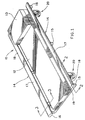
- Fig. 1 is a perspective view of the mechanic's creeper made in accordance with the concepts of the present invention.
- Fig. 2 is a fragmented, sectional view taken substantially along line 2-2 of Fig. 1.
- Fig. 3 is a sectional view taken substantially along line 3-3 of Fig. 1.
- a mechanic's creeper made in accordance with the concepts of the present invention is generally indicated by the numeral 10 and includes padding 12 and, optionally, a headrest 13 held between opposed side rails, generally indicated by the numeral 14, on a plurality of crossbars 15.
- side rails of the prior art are normally of square or rectangular cross section and therefore provide sharp edges adjacent to the padding held between the side rails.
- side rails 14 of the present invention are generally tear-shaped so as to eliminate the discomfort encountered when utilizing mechanic's creepers of the prior art.
- each side rail 14 is hollow and includes a generally horizontal bottom surface 16, which thus lies substantially parallel to the surface upon which creeper 10 is placed, and an opposed top surface 17 which is angled in relation to bottom surface 16 so as to provide a generally tapered cross section.
- the lateral outer ends of surfaces 16 and 17 are connected by an outer arcuate surface 18 and the laterally inner ends of surfaces 16 and 17 are connected by an inner arcuate surface 19.
- the radius of curvature of surface 18 is greater than that of surface 19.
- the lateral edges of surfaces 18 and 19 define the vertical profile of each rail 14.
- side rails 14 taper in the direction of padding 12 such that the surface 19 of side rails 14 is positioned adjacent to padding 12, side rails 14 and padding 12 cooperate to cradle an individual using creeper 10 to minimize any discomfort.
- the preferred shape disclosed herein for side rails 14 is a tear shape, the present invention should not be limited specifically thereto or thereby. Indeed, the basic improvement achieved sharp edges adjacent to padding 12 and, therefore, this aspect of the present invention should be understood to encompass all tapered side rail designs eliminating such sharp edges.
- Caster assemblies 20 each include a wheel assembly 22 that rotates on a vertical axis on a set of top and bottom rolling elements 24, 26, respectively, that are retained within top and bottom bearing brackets 28, 30, respectively. More specifically, top rolling elements 24 are maintained between top race 32 of top bearing bracket 28 and a horn 36 of wheel assembly 22, while bottom rolling elements 26 are maintained between a bottom race 34 of bottom bearing bracket 30 and horn 36 of wheel assembly 22.
- Horn 36 via axle 38, carries a wheel 40 such that wheel 40 may revolve on axle 38 as creeper 10 is being moved. Moreover, wheel 40 may rotate to allow for movement of creeper 10 in any direction because horn 36 is held between top and bottom rolling elements 24, 26 so as to pivot around the vertical axis defined by a kingpin or rivet 42.
- Kingpin 42 extends through apertures 44, 46 and 48 in top bearing bracket 28, bottom bearing bracket 30 and horn 36, respectively, such that horn 36 is securely retained between rolling elements 24, 26 and capable of rotating thereon. It should be noted that apertures 44 and 46 in top and bottom bearing brackets 28 and 30 abut and intimately contact kingpin 42 while aperture 48 in horn 36 provides a gap between kingpin 42 and horn 36 so as to facilitate the rotation of horn 36 and associated wheel 40 around the axis of kingpin 42.
- horn 36 is provided with top and bottom raceways 50, 52, respectively, which receive top and bottom rolling elements 24, 26, respectively.
- top and bottom raceways 50, 52 are not as defined as top and bottom races 32, 34, the position as shown in Figs. 2 and 3, wherein horn 36 rotates on rolling elements 24, 26 and is free from contact with kingpin 42.
- Kingpin 42 is substantially different from kingpins (stems) utilized in mechanic's creepers of the prior art.
- the prior art utilizes caster stems which, in addition to providing an axis for rotation of the caster assemblies, also provide the main means for attachment of the caster assemblies to the side rails.
- the stems of the prior art are basically bolts extending fully through the side rails and secured by nuts threaded thereon.
- kingpins of the prior art create protrusions on the top surface of the side rails. These protrusions inevitably cause discomfort to the individual using the mechanic's creeper -- snagging and tearing the individual's clothing and scratching the individual's body.
- kingpin 42 does not extend to or through the top surface of side rails 14. Moreover, kingpin 42, unlike kingpins (stems) of the prior art, serves only to hold the various elements of caster assembly 20 ( i . e ., top and bottom bearing brackets 28, 30, and wheel assembly 22) together, and does not attach caster assembly 20 to side rails 14.
- caster assemblies 20 of the present invention are attached to side rails 14 by two or more fasteners that will be referred to herein as rivet nuts generally indicated by the numeral 54.
- Rivet nuts 54 removably attach top bearing bracket 28 and the associated remainder of each caster assembly 20 to bottom surface 16 of each side rail 14.
- Rivet nuts 54 include rivets 56 that have a threaded bore into which bolts 58 fasten to secure top bearing bracket 28 to the bottom surface 16 of side rail 14.
- Rivet 56 of rivet nut 54 is substantially, permanently attached to bottom surface 16 of side rail 14, through apertures 60 in bottom surface 16, and provides a threaded bore for bolt 58 of rivet nut 54.
- Top bearing bracket 28 includes apertures 62 that align with rivets 56 which are secured to side rail 14, and therefore top bearing bracket 28 and the associated remainder of caster assembly 30 can be removably secured to bottom surface 16 of side rail 14 by the bolts 58 of the rivet nuts 54.
- This method of attaching caster assemblies 20 to side rails 14, results in a top surface 17 of side rails 14, without any protrusions,which is another novel aspect of the present invention
- side rails 14 are not only tear shaped, but also have a vertical profile, as previously described, which is sufficiently wide so as to fully contact and cover the entire circumference of top race 32.
- Top race 32 therefore lies wholly within the vertical profile of side rails 14.
- the bearing races are of larger diameter than the width of the side rails to which they attach which renders the caster assemblies susceptible to damage and creates weaknesses in the nuts securing the bolts used to secure the caster assemblies to the side rails.
- this prior art design increases the wear and tear to the bearings because the weight placed on the prior art mechanic's creeper is not evenly distributed to the bearing race.
- the preferred embodiment of the present invention solves this problem by ensuring that top race 32 fully engages and is fully encompassed within the profile of side rails 14.
Abstract
Description
- The present invention relates to mechanic's creepers and, more particularly, to a mechanic's creeper having an improved side rail and caster assembly providing a more contoured fit for the user, improved resistance to wear and tear, and a lack of protrusions on the side rails so as to avoid the snagging and tearing of clothes and possible scratches to the user's body.
- Mechanic's creepers are in wide-spread use, however, it has been found that the common, prior art mechanic's creeper design can be improved in a number of ways. Currently, mechanic's creepers are designed with side rails usually of rectangular or square cross section. The side rails thus provide sharp edges that lie adjacent to the padding held between the side rails. Because the padding sections provided between the side rails are not normally as wide as the breadth of the shoulders of the typical user, the sharp edges can often present a discomfort to the user.
- Also, the casters on the typical mechanic's creeper are attached to the side rails in such a way as to provide protrusions on the top surface of the side rails. These protrusions can be an additional source of discomfort to the user because they are likely to snag and tear the user's clothing and scratch the user's body. More specifically, in mechanic's creepers of the prior art, the casters are attached to the side rails by means of a caster-carrying stud that is inserted through both the top and bottom walls of the side rail and secured by a nut threaded thereon. The remainder of the caster assembly is thereby positioned below the side rail and a bolt-head protrusion is undesirably located on the top surface of the side rail.
- The width of the side rails in mechanic's creepers of the prior art relative to the diameter of the caster raceways needed to support the creeper also presents problems. Prior art mechanic's creeper designs incorporate caster assemblies having bearing races that are of larger diameter than the width of the side rails such that a portion of the bearing race extends beyond the sides of the side rails. As such, the portion of the bearing race which extends beyond the side rails is susceptible to being bumped or otherwise contacted which could readily loosen or otherwise damage the caster assembly. Moreover, since the bearing race does not fully engage the side rail all the way around the race, the rocking forces born by the caster assemblies as the mechanic's creeper is utilized creates weaknesses in the caster assemblies. For instance, the nuts securing the bolts through the side rails tend to loosen due to the torque placed upon the stem of the bolt as the creeper is moved and the caster assemblies roll and change directions. Moreover, adverse forces on the caster stems may well cause a shearing of these stems. In addition, because the bearing races do not completely engage the side rails, the weight placed upon the mechanic's creeper (i.e., the weight of the user's body) is not evenly distributed to the bearing race and the bearings therein. This increases the wearing of the bearings and therefore shortens the useful life of the caster assemblies and the mechanic's creeper as a whole.
- Thus, there exists a need in the art for a mechanic's creeper design that provides a more comfortable, contoured fit for the user when lying down on the pads held between the side rails. Additionally, there exists a need in the art for a mechanic's creeper in which the caster assemblies are attached to the side rails without creating any protrusions on the top surface of the side rails and which also attach in a manner that prevents wear and tear to the bearings and the bearing races such as encountered with current mechanic's creeper designs.
- In general, a creeper made in accordance with the present invention includes a pad supported between opposed side rails. A plurality of caster assemblies attach to and support the side rails.
- In accordance with one aspect of the present invention, the top surface of the side rails tapers toward the bottom surface of the side rails to define a decreased cross section of the rails, that decreased cross section being positioned adjacent to the pad.
- In accordance with another aspect of the present invention, the caster assemblies include top and bottom bearing brackets providing, respectively, top and bottom races, and the caster assemblies are attached to the side rails such that the top race of the top bearing bracket lies wholly within the vertical profile of the side rail.
- In accordance with yet another aspect of the present invention, the caster assemblies are attached to the side rails so as not to create a protrusion on the top surface of the side rails.
- A preferred exemplary mechanic's creeper incorporating the concepts of the present invention is shown by way of example in the accompanying drawings without attempting to show all the various forms and modifications in which the invention might be embodied, the invention being measured by the appended claims and not by the details of the specification.
- Fig. 1 is a perspective view of the mechanic's creeper made in accordance with the concepts of the present invention.
- Fig. 2 is a fragmented, sectional view taken substantially along line 2-2 of Fig. 1.
- Fig. 3 is a sectional view taken substantially along line 3-3 of Fig. 1.
- A mechanic's creeper made in accordance with the concepts of the present invention is generally indicated by the
numeral 10 and includes padding 12 and, optionally, aheadrest 13 held between opposed side rails, generally indicated by thenumeral 14, on a plurality ofcrossbars 15. As hereinabove discussed, side rails of the prior art are normally of square or rectangular cross section and therefore provide sharp edges adjacent to the padding held between the side rails. However, as seen in Figs. 1 and 3,side rails 14 of the present invention are generally tear-shaped so as to eliminate the discomfort encountered when utilizing mechanic's creepers of the prior art. As such, eachside rail 14 is hollow and includes a generallyhorizontal bottom surface 16, which thus lies substantially parallel to the surface upon whichcreeper 10 is placed, and an opposedtop surface 17 which is angled in relation tobottom surface 16 so as to provide a generally tapered cross section. The lateral outer ends ofsurfaces arcuate surface 18 and the laterally inner ends ofsurfaces arcuate surface 19. Of course, because of the taper, just described, the radius of curvature ofsurface 18 is greater than that ofsurface 19. The lateral edges ofsurfaces rail 14. - Since
side walls 14 taper in the direction ofpadding 12 such that thesurface 19 ofside rails 14 is positioned adjacent to padding 12,side rails 14 and padding 12 cooperate to cradle anindividual using creeper 10 to minimize any discomfort. It should be readily understood that, while the preferred shape disclosed herein forside rails 14 is a tear shape, the present invention should not be limited specifically thereto or thereby. Indeed, the basic improvement achieved sharp edges adjacent to padding 12 and, therefore, this aspect of the present invention should be understood to encompass all tapered side rail designs eliminating such sharp edges. -
Padding 12,side rails 14 andcrossbars 15 are held off the ground and made mobile by a plurality of caster assemblies generally indicated by thenumeral 20 and attached to thebottom surface 16 ofside rails 14 in a manner as will be hereinafter described. Caster assemblies 20 each include awheel assembly 22 that rotates on a vertical axis on a set of top and bottomrolling elements brackets rolling elements 24 are maintained betweentop race 32 of top bearingbracket 28 and ahorn 36 ofwheel assembly 22, whilebottom rolling elements 26 are maintained between abottom race 34 of bottom bearingbracket 30 andhorn 36 ofwheel assembly 22. Horn 36, viaaxle 38, carries awheel 40 such thatwheel 40 may revolve onaxle 38 ascreeper 10 is being moved. Moreover,wheel 40 may rotate to allow for movement ofcreeper 10 in any direction becausehorn 36 is held between top and bottomrolling elements rivet 42. - Kingpin 42 extends through
apertures bracket 28,bottom bearing bracket 30 andhorn 36, respectively, such thathorn 36 is securely retained betweenrolling elements apertures brackets kingpin 42 whileaperture 48 inhorn 36 provides a gap betweenkingpin 42 andhorn 36 so as to facilitate the rotation ofhorn 36 and associatedwheel 40 around the axis ofkingpin 42. To ensure that the gap provided byaperture 48 is not easily compromised by a shifting ofhorn 36, and also to facilitate the rotation ofhorn 36 around the axis ofkingpin 42,horn 36 is provided with top andbottom raceways bottom rolling elements bottom raceways bottom races horn 36 rotates onrolling elements kingpin 42. - Kingpin 42 is substantially different from kingpins (stems) utilized in mechanic's creepers of the prior art. The prior art utilizes caster stems which, in addition to providing an axis for rotation of the caster assemblies, also provide the main means for attachment of the caster assemblies to the side rails. Unlike
kingpin 42 of the present invention, the stems of the prior art are basically bolts extending fully through the side rails and secured by nuts threaded thereon. Thus, kingpins of the prior art create protrusions on the top surface of the side rails. These protrusions inevitably cause discomfort to the individual using the mechanic's creeper -- snagging and tearing the individual's clothing and scratching the individual's body. As is clearly shown herein,kingpin 42 does not extend to or through the top surface ofside rails 14. Moreover,kingpin 42, unlike kingpins (stems) of the prior art, serves only to hold the various elements of caster assembly 20 (i.e., top and bottom bearingbrackets caster assembly 20 toside rails 14. - Rather, caster assemblies 20 of the present invention are attached to
side rails 14 by two or more fasteners that will be referred to herein as rivet nuts generally indicated by thenumeral 54.Rivet nuts 54 removably attach top bearingbracket 28 and the associated remainder of eachcaster assembly 20 tobottom surface 16 of eachside rail 14.Rivet nuts 54 include rivets 56 that have a threaded bore into whichbolts 58 fasten to secure top bearingbracket 28 to thebottom surface 16 ofside rail 14. Rivet 56 ofrivet nut 54 is substantially, permanently attached tobottom surface 16 ofside rail 14, throughapertures 60 inbottom surface 16, and provides a threaded bore forbolt 58 ofrivet nut 54. Top bearingbracket 28 includesapertures 62 that align with rivets 56 which are secured toside rail 14, and therefore top bearingbracket 28 and the associated remainder ofcaster assembly 30 can be removably secured tobottom surface 16 ofside rail 14 by thebolts 58 of therivet nuts 54. This method of attaching caster assemblies 20 toside rails 14, results in atop surface 17 ofside rails 14, without any protrusions,which is another novel aspect of the present invention - Finally, in the preferred embodiment of the present invention, side rails 14 are not only tear shaped, but also have a vertical profile, as previously described, which is sufficiently wide so as to fully contact and cover the entire circumference of
top race 32.Top race 32 therefore lies wholly within the vertical profile of side rails 14. As previously described, in the prior art, the bearing races are of larger diameter than the width of the side rails to which they attach which renders the caster assemblies susceptible to damage and creates weaknesses in the nuts securing the bolts used to secure the caster assemblies to the side rails. Also, this prior art design increases the wear and tear to the bearings because the weight placed on the prior art mechanic's creeper is not evenly distributed to the bearing race. The preferred embodiment of the present invention solves this problem by ensuring thattop race 32 fully engages and is fully encompassed within the profile of side rails 14. - In light of the foregoing, it should thus be evident that a mechanic's creeper constructed as described herein substantially improves the art and otherwise accomplishes the objects of the present invention. While only the best mode and preferred embodiment of the invention has been presented and described in detail, it is to be understood that the invention is not limited thereto or thereby. It will be appreciated, therefore, that the invention includes subject matter defined in the following paragraphs:
- 1. A creeper comprising opposed side rails; a pad supported between said side rails; and a plurality of caster assemblies attached to and supporting said side rails; said side rails having a top and bottom surface, said top surface tapering toward said bottom surface to define a decreased cross section of said side rails, the decreased cross section of said side rails being positioned adjacent said pad.
- 2. A creeper according to paragraph 1 wherein said bottom surface of said side rails lies substantially parallel to the surface upon which the creeper is placed, and said top surface of said side rails is angled in relation to said bottom surface.
- 3. A creeper according to
paragraph 2 wherein said side rails are substantially tear shaped such that no sharp or abrupt edges are provided by side rails. - 4. A creeper according to paragraph 1 wherein each of said plurality of caster assemblies each include a top bearing bracket having a top race, each said top bearing bracket being attached to one of said side rails such that each said top race of each said top bearing bracket lies wholly within the vertical profile of said side rail.
- 5. A creeper according to paragraph 4 wherein each of said plurality of caster assemblies further include a bottom bearing bracket having a bottom race; a wheel assembly connected to said caster assembly between said top and bottom bearing brackets; top rolling elements retained within said top race between said top bearing bracket and a portion of said wheel assembly; and bottom rolling elements retained within said bottom race between said bottom bearing bracket and a portion of said wheel assembly.
- 6. A creeper according to paragraph 5 wherein said wheel assembly includes a horn connected to said caster assembly between said top and bottom bearing brackets; an axle carried by said horn; and a wheel retained on said axle.
- 7. A creeper according to paragraph 6 wherein said horn forms top and bottom raceways to respectively receive said top and bottom rolling elements.
- 8. A creeper according to paragraph 1 wherein said plurality of caster assemblies are attached to said side rails without creating a protrusion on said top surface of said side rails.
- 9. A creeper according to paragraph 8 wherein said plurality of caster assemblies each include a top bearing bracket that is attached to said bottom surface of said side rails, said top bearing bracket providing a top race.
- 10. A creeper according to paragraph 9 wherein each of said plurality of caster assemblies further include a bottom bearing bracket having a bottom race; a wheel assembly connected to said caster assembly between said top and bottom bearing brackets; top rolling elements retained within said top race between said top bearing bracket and a portion of said wheel assembly; bottom rolling elements retained within said bottom race between said bottom bearing bracket and said wheel assembly; and a kingpin, said top and bottom bearing brackets and said wheel assembly being held in operative position by said kingpin.
- 11. A creeper according to
paragraph 10 wherein said top bearing bracket is secured to said bottom surface of said side rails by rivet nuts. - 12. A creeper according to paragraph 8 wherein each of said plurality of caster assemblies include a top bearing bracket having a top race, each said top bearing bracket being attached to one of said side rails such that each said top race of each said top bearing bracket lies wholly within the vertical profile of said side rail.
- 13. A creeper comprising opposed side rails, each having a top and bottom surface; a pad supported between said side rails; and a plurality of caster assemblies each including a top bearing bracket having a top race, said top bearing bracket being attached to one of said side rails such that said top race of said top bearing bracket lies wholly within the vertical profile of said side rail.
- 14. A creeper according to
paragraph 13 wherein each of said plurality of caster assemblies further include a bottom bearing bracket having a bottom race; a wheel assembly connected to said caster assembly between said top and bottom bearing brackets; top rolling elements retained within said top race between said top bearing bracket and a portion of said wheel assembly; bottom rolling elements retained within said bottom race between said bottom bearing bracket and a portion of said wheel assembly. - 15. A creeper according to
paragraph 14 wherein said wheel assembly includes a horn connected to said caster assembly between said top and bottom bearing brackets; an axle carried by said horn; and a wheel retained on said axle. - 16. A creeper according to
paragraph 15 wherein said horn forms top and bottom raceways to respectively receive said top and bottom rolling elements. - 17. A creeper according to
paragraph 13 wherein said plurality of caster assemblies are attached to said side rails without creating a protrusion on said top surface of said side rails. - 18. A creeper according to
paragraph 17 wherein each of said plurality of caster assemblies include a top bearing bracket that is attached to said bottom surface of said side rails, said top bearing bracket providing said top race. - 19. A creeper according to
paragraph 18 wherein each said plurality of caster assemblies further include a bottom bearing bracket having a bottom race; a wheel assembly connected to said caster assembly between said top and bottom bearing brackets; top rolling elements retained within said top race between said top bearing bracket and a portion of said wheel assembly; bottom rolling elements retained within said bottom race between said bottom bearing bracket and said wheel assembly; and a kingpin, said top and bottom bearing brackets and said wheel assembly being held in operative position by said kingpin. - 20. A creeper according to
paragraph 19 wherein said top bearing bracket is secured to said bottom surface of said side rail by rivet nuts. - 21. A creeper comprising opposed side rails, each having a top and bottom surface; a pad supported between said side rails; and a plurality of caster assemblies attached to and supporting said side rails without creating a protrusion on said top surface of said side rails.
- 22. A creeper according to paragraph 21 wherein said caster assemblies each include a top bearing bracket having a top race, and a bottom bearing bracket having a bottom race; a wheel assembly connected to said caster assembly between said top and bottom bearing brackets; top rolling elements retained within said top race between said top bearing bracket and a portion of said wheel assembly; and bottom rolling elements retained within said bottom race between said bottom bearing bracket and a portion of said wheel assembly.
- 23. A creeper according to
paragraph 22 wherein each of said caster assemblies further include a kingpin, said bottom bearing bracket and said wheel assembly being held in operative position by said kingpin. - 24. A creeper according to paragraph 23 wherein said top bearing bracket is secured to said bottom surface of said side rails by rivet nuts.
- 25. A creeper comprising opposed side rails of a tapered cross section, each having a top and bottom surface; and a plurality of caster assemblies attached to and supporting said side rails, said caster assemblies each including a top bearing bracket attached to only the bottom surface of one of said rails and providing a top race that lies wholly within the vertical profile of said side rail, each said caster assembly also including a kingpin holding said caster assembly in operative relation, wherein said kingpin does not extend through said top surface of said side rail.
-
Claims (12)
- A creeper (10) comprising opposed side rails (14); a pad (12) supported between said side rails (14); and a plurality of caster assemblies (20) attached to and supporting said side rails (14); said side rails (14) having a top (17) and bottom (16) surface, said top surface (17) tapering toward said bottom surface (16) to define a decreased cross section of said side rails (14), the decreased cross section of said side rails (14) being positioned adjacent said pad (12).
- A creeper according to claim 1 wherein said bottom surface (16) of said side rails (14) lies substantially parallel to the surface upon which the creeper is placed, and said top surface (17) of said side rails (14) is angled in relation to said bottom surface (16), and optionally wherein said side rails (14) are substantially tear shaped such that no sharp or abrupt edges are provided by the side rails.
- A creeper according to claim 1 or claim 2 wherein each of said plurality of caster assemblies (20) includes a top bearing bracket (28) having a top race (32), each said top bearing bracket (28) being attached to one of said side rails (14) such that each said top race (32) of each said top bearing bracket (28) lies wholly within the vertical profile of said side rail (14).
- A creeper according to claim 3 wherein each of said plurality of caster assemblies (20) further includes a bottom bearing bracket (30) having a bottom race (34); a wheel assembly (22) connected to said caster assembly (20) between said top (28) and bottom (30) bearing brackets; top rolling elements (24) retained within said top race (32) between said top bearing bracket (28) and a portion of said wheel assembly (20); and bottom rolling elements (26) retained within said bottom race (34) between said bottom bearing bracket (30) and a portion of said wheel assembly (20).
- A creeper according to claim 4 which further comprises a kingpin (42), said top (28) and bottom (30) bearing brackets and said wheel assembly (22) being held in operative position by said kingpin (42).
- A creeper according to claim 4 or claim 5 wherein said wheel assembly (20) includes a horn (36) connected to said caster assembly (20) between said top (28) and bottom (30) bearing brackets; an axle (38) carried by said horn; and a wheel (40) retained on said axle.
- A creeper according to claim 5 wherein said horn (36) forms top (50) and bottom (52) raceways to respectively receive said top (24) and bottom (26) rolling elements.
- A creeper according to any of claims 3 to 7 wherein said top bearing bracket (28) is secured to said bottom surface (16) of said side rails by rivet nuts (54).
- A creeper according to any of claims 1 to 8 wherein said plurality of caster assemblies (20) are attached to said side rails (14) without creating a protrusion on said top surface of said side rails.
- A creeper comprising opposed side rails (14), each having a top (17) and bottom (16) surface; a pad (12) supported between said side rails; and a plurality of caster assemblies (20) each including a top bearing bracket having a top race (32), said top bearing bracket (28) being attached to one of said side rails (14) such that said top race (32) of said top bearing bracket (28) lies wholly within the vertical profile of said side rail (14), and which optionally further includes the feature(s) recited in one or more of claims 2 to 9.
- A creeper comprising opposed side rails (14), each having a top (17) and bottom (16) surface; a pad (12) supported between said side rails (14); and a plurality of caster assemblies (20) attached to and supporting said side rails (14) without creating a protrusion on said top surface of said side rails (14), and optionally further including the feature(s) recited in one or more of claims 2 to 8.
- A creeper comprising opposed side rails (14) of a tapered cross section, each having a top (17) and bottom (16) surface; and a plurality of caster assemblies (20) attached to and supporting said side rails (14), said caster assemblies (14) each including a top bearing bracket (28) attached to only the bottom surface (16) of one of said rails (14) and providing a top race (32) that lies wholly within the vertical profile of said side rail (14), each said caster assembly also including a kingpin (42) holding said caster assembly in operative relation, wherein said kingpin (42) does not extend through said top surface of said side rail.
Applications Claiming Priority (2)
| Application Number | Priority Date | Filing Date | Title |
|---|---|---|---|
| US523469 | 2000-03-10 | ||
| US09/523,469 US6705622B2 (en) | 2000-03-10 | 2000-03-10 | Mechanic's creeper |
Publications (1)
| Publication Number | Publication Date |
|---|---|
| EP1132181A1 true EP1132181A1 (en) | 2001-09-12 |
Family
ID=24085150
Family Applications (1)
| Application Number | Title | Priority Date | Filing Date |
|---|---|---|---|
| EP01200538A Withdrawn EP1132181A1 (en) | 2000-03-10 | 2001-02-16 | Mechanic's creeper |
Country Status (4)
| Country | Link |
|---|---|
| US (1) | US6705622B2 (en) |
| EP (1) | EP1132181A1 (en) |
| CN (1) | CN1185998C (en) |
| CA (1) | CA2327151A1 (en) |
Cited By (3)
| Publication number | Priority date | Publication date | Assignee | Title |
|---|---|---|---|---|
| GB2373178A (en) * | 2001-02-12 | 2002-09-18 | Whiteside Mfg Co | Mechanics creeper with tear-shaped side bars, wheels with rounded radial surfaces and casters attached by brackets |
| US6831462B2 (en) * | 2001-04-17 | 2004-12-14 | Ge Medical Systems Global Technology Company, Llc | Floor cover and MR system |
| CN102513984A (en) * | 2011-12-08 | 2012-06-27 | 铜陵恒盛轨道装备有限责任公司 | Axle shaft transporting bogie |
Families Citing this family (14)
| Publication number | Priority date | Publication date | Assignee | Title |
|---|---|---|---|---|
| US7032908B2 (en) * | 2003-09-05 | 2006-04-25 | Melvin Darrell E | Mechanic's creeper |
| US7293783B2 (en) * | 2005-02-03 | 2007-11-13 | Whiteside Manufacturing Co. | Creeper with trays |
| US7478818B1 (en) * | 2005-02-03 | 2009-01-20 | Whiteside Mfg. Co. | Creeper without side rails |
| US7481438B2 (en) * | 2006-07-17 | 2009-01-27 | Alltrade Tools, Llc | Multi-position mechanic's creeper with tool tray |
| CN103395050A (en) * | 2013-07-12 | 2013-11-20 | 太仓市豪阳汽车内饰件有限公司 | Movable device for automobile maintenance |
| US9272411B1 (en) | 2015-05-05 | 2016-03-01 | Whiteside Mfg. Co. | Mechanic's creeper |
| US9339928B1 (en) | 2015-05-05 | 2016-05-17 | Whiteside Mfg. Co. | Mechanic's creeper |
| US9242369B1 (en) * | 2015-06-04 | 2016-01-26 | Prince Richmond, Jr. | Creeper for underneath an automobile dashboard |
| US9969215B1 (en) * | 2016-10-27 | 2018-05-15 | Whiteside Mfg. Co. | Frame for a creeper |
| CN106347025B (en) * | 2016-11-28 | 2018-10-23 | 武汉资联虹康科技股份有限公司 | A kind of Anti-slip castor and medical imaging devices |
| US10328570B1 (en) * | 2018-04-18 | 2019-06-25 | Shinn Fu Company Of America, Inc. | Creeper |
| US10549418B1 (en) * | 2018-08-03 | 2020-02-04 | The Boeing Company | Adjustable support device for ergonomically supporting a worker for accessing a lower work area |
| CN112122835B (en) * | 2020-10-23 | 2022-04-15 | 常州市威达铭博自动化有限公司 | High-efficiency welding robot workstation |
| CN113693834B (en) * | 2021-08-26 | 2023-07-21 | 北京市自来水集团禹通市政工程有限公司 | Multifunctional night rush-repair vehicle |
Citations (5)
| Publication number | Priority date | Publication date | Assignee | Title |
|---|---|---|---|---|
| US2487706A (en) * | 1946-12-13 | 1949-11-08 | James V Happ | Repairman's creeper |
| US2879865A (en) * | 1957-05-07 | 1959-03-31 | Simmons Ballard | Lock wheel mechanic's creeper |
| US4570957A (en) * | 1984-12-10 | 1986-02-18 | Rose James W | Mechanic's creeper |
| US5895062A (en) * | 1995-09-11 | 1999-04-20 | United Auto Systems, Inc. | Foldable creeper |
| US5947489A (en) * | 1996-10-23 | 1999-09-07 | E-Z Red Company | Foldable creeper |
Family Cites Families (14)
| Publication number | Priority date | Publication date | Assignee | Title |
|---|---|---|---|---|
| US1882497A (en) * | 1929-01-02 | 1932-10-11 | Jarvis & Jarvis Inc | Bearing construction |
| US1769548A (en) * | 1929-02-13 | 1930-07-01 | Benard E Rodin | Auto creeper |
| US2683734A (en) * | 1950-09-11 | 1954-07-13 | Ciba Ltd | Method of concentrating gaseous hydrocyanic acid and the use of the method in the manufacture of acrylonitrile |
| US4707880A (en) * | 1986-03-04 | 1987-11-24 | Stewart-Warner Corporation | Swivel caster assembly and method of making |
| US5174592A (en) * | 1989-02-02 | 1992-12-29 | Lisle Corporation | Low profile mechanic's creeper |
| US5263226A (en) * | 1989-10-17 | 1993-11-23 | Guitel-Etienne Mobilor | Swiveling wheel assembly for a cart |
| US5199131A (en) * | 1991-06-26 | 1993-04-06 | Babcock Industries, Inc. | Thermoplastic caster assembly |
| US5287594A (en) * | 1992-06-08 | 1994-02-22 | Hicks Jimmy L | Shopping cart swivel yoke assembly with plastic bearing races |
| US5472219A (en) * | 1994-07-26 | 1995-12-05 | Eckstrum; Kurt C. | Combination automotive creeper and braking apparatus therefore |
| US5527051A (en) * | 1995-02-03 | 1996-06-18 | P & B Manufacturing Co. | Mechanic's creeper |
| US5745951A (en) * | 1996-02-23 | 1998-05-05 | Interstore Transfer Systems, Ltd. | Directional control caster assembly |
| US5813090A (en) * | 1997-01-22 | 1998-09-29 | United Auto Systems Inc. | Caster with D-shaped stem |
| USD406433S (en) * | 1997-04-25 | 1999-03-02 | United System, Inc. | Drop shoulder creeper with T-bar support |
| US6076838A (en) * | 1998-06-30 | 2000-06-20 | Peterson; Terry W. | Manually operated creeper and brake mechanism therefor |
-
2000
- 2000-03-10 US US09/523,469 patent/US6705622B2/en not_active Expired - Fee Related
- 2000-11-30 CA CA002327151A patent/CA2327151A1/en not_active Abandoned
-
2001
- 2001-02-08 CN CN01103708.3A patent/CN1185998C/en not_active Expired - Fee Related
- 2001-02-16 EP EP01200538A patent/EP1132181A1/en not_active Withdrawn
Patent Citations (5)
| Publication number | Priority date | Publication date | Assignee | Title |
|---|---|---|---|---|
| US2487706A (en) * | 1946-12-13 | 1949-11-08 | James V Happ | Repairman's creeper |
| US2879865A (en) * | 1957-05-07 | 1959-03-31 | Simmons Ballard | Lock wheel mechanic's creeper |
| US4570957A (en) * | 1984-12-10 | 1986-02-18 | Rose James W | Mechanic's creeper |
| US5895062A (en) * | 1995-09-11 | 1999-04-20 | United Auto Systems, Inc. | Foldable creeper |
| US5947489A (en) * | 1996-10-23 | 1999-09-07 | E-Z Red Company | Foldable creeper |
Cited By (4)
| Publication number | Priority date | Publication date | Assignee | Title |
|---|---|---|---|---|
| GB2373178A (en) * | 2001-02-12 | 2002-09-18 | Whiteside Mfg Co | Mechanics creeper with tear-shaped side bars, wheels with rounded radial surfaces and casters attached by brackets |
| GB2373178B (en) * | 2001-02-12 | 2003-07-30 | Whiteside Mfg Co | Mechanics creeper |
| US6831462B2 (en) * | 2001-04-17 | 2004-12-14 | Ge Medical Systems Global Technology Company, Llc | Floor cover and MR system |
| CN102513984A (en) * | 2011-12-08 | 2012-06-27 | 铜陵恒盛轨道装备有限责任公司 | Axle shaft transporting bogie |
Also Published As
| Publication number | Publication date |
|---|---|
| CN1313076A (en) | 2001-09-19 |
| US6705622B2 (en) | 2004-03-16 |
| US20020060437A1 (en) | 2002-05-23 |
| CA2327151A1 (en) | 2001-09-10 |
| CN1185998C (en) | 2005-01-26 |
Similar Documents
| Publication | Publication Date | Title |
|---|---|---|
| US6705622B2 (en) | Mechanic's creeper | |
| US6241276B1 (en) | Auxiliary wheel assembly | |
| US20060170170A1 (en) | Creeper with trays | |
| US6089545A (en) | Converter for converting a conventional car jack into a transmission jack | |
| US7213815B2 (en) | Mechanic's creeper | |
| US7374185B1 (en) | Bilevel, cantilevered, angled platform welding cart with cylinder rack | |
| EP1614652A3 (en) | Device for offering goods for sale | |
| US5024312A (en) | Boat support roller assembly | |
| US4925197A (en) | Pivotal creeper | |
| JPS6265894A (en) | Supporter for car lifting gear | |
| EP0930054A3 (en) | A wheel chair | |
| US20160332483A1 (en) | Compact mechanic's creeper | |
| CN109789049B (en) | Walking support device | |
| US4527484A (en) | Conveyor apparatus, particularly for suspension conveyance | |
| US7401630B2 (en) | Wheelchair, wheel for wheelchair, and method of producing wheel for wheelchair | |
| US9272411B1 (en) | Mechanic's creeper | |
| US9969215B1 (en) | Frame for a creeper | |
| JP6885586B2 (en) | Chock | |
| US6115882A (en) | Caster with a shaped stem | |
| US1920004A (en) | Caster | |
| AU2012216295A1 (en) | Spare tire carrier | |
| CN218112845U (en) | Take-out goods shelf and electric vehicle | |
| JP3046835U (en) | Wheelchair casters with ring leaf springs | |
| JP2001055179A (en) | Crop harvest work vehicle for vegetable or the like | |
| JPH0223500Y2 (en) |
Legal Events
| Date | Code | Title | Description |
|---|---|---|---|
| PUAI | Public reference made under article 153(3) epc to a published international application that has entered the european phase |
Free format text: ORIGINAL CODE: 0009012 |
|
| AK | Designated contracting states |
Kind code of ref document: A1 Designated state(s): AT BE CH CY DE DK ES FI FR GB GR IE IT LI LU MC NL PT SE TR |
|
| AX | Request for extension of the european patent |
Free format text: AL;LT;LV;MK;RO;SI |
|
| 17P | Request for examination filed |
Effective date: 20020225 |
|
| AKX | Designation fees paid |
Free format text: AT BE CH CY DE DK ES FI FR GB GR IE IT LI LU MC NL PT SE TR |
|
| 17Q | First examination report despatched |
Effective date: 20060601 |
|
| STAA | Information on the status of an ep patent application or granted ep patent |
Free format text: STATUS: THE APPLICATION IS DEEMED TO BE WITHDRAWN |
|
| 18D | Application deemed to be withdrawn |
Effective date: 20070706 |