EP1132038A2 - Dishwashing machine with differentiated washing capabilities - Google Patents
Dishwashing machine with differentiated washing capabilities Download PDFInfo
- Publication number
- EP1132038A2 EP1132038A2 EP01104760A EP01104760A EP1132038A2 EP 1132038 A2 EP1132038 A2 EP 1132038A2 EP 01104760 A EP01104760 A EP 01104760A EP 01104760 A EP01104760 A EP 01104760A EP 1132038 A2 EP1132038 A2 EP 1132038A2
- Authority
- EP
- European Patent Office
- Prior art keywords
- liquid
- sprayer
- dishwashing machine
- flow
- crockery
- Prior art date
- Legal status (The legal status is an assumption and is not a legal conclusion. Google has not performed a legal analysis and makes no representation as to the accuracy of the status listed.)
- Granted
Links
Images

Classifications
-
- A—HUMAN NECESSITIES
- A47—FURNITURE; DOMESTIC ARTICLES OR APPLIANCES; COFFEE MILLS; SPICE MILLS; SUCTION CLEANERS IN GENERAL
- A47L—DOMESTIC WASHING OR CLEANING; SUCTION CLEANERS IN GENERAL
- A47L15/00—Washing or rinsing machines for crockery or tableware
- A47L15/42—Details
- A47L15/4293—Arrangements for programme selection, e.g. control panels; Indication of the selected programme, programme progress or other parameters of the programme, e.g. by using display panels
-
- A—HUMAN NECESSITIES
- A47—FURNITURE; DOMESTIC ARTICLES OR APPLIANCES; COFFEE MILLS; SPICE MILLS; SUCTION CLEANERS IN GENERAL
- A47L—DOMESTIC WASHING OR CLEANING; SUCTION CLEANERS IN GENERAL
- A47L15/00—Washing or rinsing machines for crockery or tableware
- A47L15/0018—Controlling processes, i.e. processes to control the operation of the machine characterised by the purpose or target of the control
- A47L15/0055—Metering or indication of used products, e.g. type or quantity of detergent, rinse aid or salt; for measuring or controlling the product concentration
-
- A—HUMAN NECESSITIES
- A47—FURNITURE; DOMESTIC ARTICLES OR APPLIANCES; COFFEE MILLS; SPICE MILLS; SUCTION CLEANERS IN GENERAL
- A47L—DOMESTIC WASHING OR CLEANING; SUCTION CLEANERS IN GENERAL
- A47L15/00—Washing or rinsing machines for crockery or tableware
- A47L15/42—Details
- A47L15/4214—Water supply, recirculation or discharge arrangements; Devices therefor
- A47L15/4219—Water recirculation
- A47L15/4221—Arrangements for redirection of washing water, e.g. water diverters to selectively supply the spray arms
-
- A—HUMAN NECESSITIES
- A47—FURNITURE; DOMESTIC ARTICLES OR APPLIANCES; COFFEE MILLS; SPICE MILLS; SUCTION CLEANERS IN GENERAL
- A47L—DOMESTIC WASHING OR CLEANING; SUCTION CLEANERS IN GENERAL
- A47L15/00—Washing or rinsing machines for crockery or tableware
- A47L15/42—Details
- A47L15/4287—Temperature measuring or regulating arrangements
-
- A—HUMAN NECESSITIES
- A47—FURNITURE; DOMESTIC ARTICLES OR APPLIANCES; COFFEE MILLS; SPICE MILLS; SUCTION CLEANERS IN GENERAL
- A47L—DOMESTIC WASHING OR CLEANING; SUCTION CLEANERS IN GENERAL
- A47L15/00—Washing or rinsing machines for crockery or tableware
- A47L15/42—Details
- A47L15/4289—Spray-pressure measuring or regulating arrangements
-
- A—HUMAN NECESSITIES
- A47—FURNITURE; DOMESTIC ARTICLES OR APPLIANCES; COFFEE MILLS; SPICE MILLS; SUCTION CLEANERS IN GENERAL
- A47L—DOMESTIC WASHING OR CLEANING; SUCTION CLEANERS IN GENERAL
- A47L2301/00—Manual input in controlling methods of washing or rinsing machines for crockery or tableware, i.e. information entered by a user
- A47L2301/06—Crockery or tableware details, e.g. material, quantity, condition
-
- A—HUMAN NECESSITIES
- A47—FURNITURE; DOMESTIC ARTICLES OR APPLIANCES; COFFEE MILLS; SPICE MILLS; SUCTION CLEANERS IN GENERAL
- A47L—DOMESTIC WASHING OR CLEANING; SUCTION CLEANERS IN GENERAL
- A47L2401/00—Automatic detection in controlling methods of washing or rinsing machines for crockery or tableware, e.g. information provided by sensors entered into controlling devices
- A47L2401/02—Consumable products information, e.g. information on detergent, rinsing aid or salt; Dispensing device information, e.g. information on the type, e.g. detachable, or status of the device
- A47L2401/023—Quantity or concentration of the consumable product
-
- A—HUMAN NECESSITIES
- A47—FURNITURE; DOMESTIC ARTICLES OR APPLIANCES; COFFEE MILLS; SPICE MILLS; SUCTION CLEANERS IN GENERAL
- A47L—DOMESTIC WASHING OR CLEANING; SUCTION CLEANERS IN GENERAL
- A47L2401/00—Automatic detection in controlling methods of washing or rinsing machines for crockery or tableware, e.g. information provided by sensors entered into controlling devices
- A47L2401/12—Water temperature
-
- A—HUMAN NECESSITIES
- A47—FURNITURE; DOMESTIC ARTICLES OR APPLIANCES; COFFEE MILLS; SPICE MILLS; SUCTION CLEANERS IN GENERAL
- A47L—DOMESTIC WASHING OR CLEANING; SUCTION CLEANERS IN GENERAL
- A47L2401/00—Automatic detection in controlling methods of washing or rinsing machines for crockery or tableware, e.g. information provided by sensors entered into controlling devices
- A47L2401/20—Time, e.g. elapsed operating time
-
- A—HUMAN NECESSITIES
- A47—FURNITURE; DOMESTIC ARTICLES OR APPLIANCES; COFFEE MILLS; SPICE MILLS; SUCTION CLEANERS IN GENERAL
- A47L—DOMESTIC WASHING OR CLEANING; SUCTION CLEANERS IN GENERAL
- A47L2501/00—Output in controlling method of washing or rinsing machines for crockery or tableware, i.e. quantities or components controlled, or actions performed by the controlling device executing the controlling method
- A47L2501/03—Water recirculation, e.g. control of distributing valves for redirection of water flow
-
- A—HUMAN NECESSITIES
- A47—FURNITURE; DOMESTIC ARTICLES OR APPLIANCES; COFFEE MILLS; SPICE MILLS; SUCTION CLEANERS IN GENERAL
- A47L—DOMESTIC WASHING OR CLEANING; SUCTION CLEANERS IN GENERAL
- A47L2501/00—Output in controlling method of washing or rinsing machines for crockery or tableware, i.e. quantities or components controlled, or actions performed by the controlling device executing the controlling method
- A47L2501/04—Water pressure or flow rate
-
- A—HUMAN NECESSITIES
- A47—FURNITURE; DOMESTIC ARTICLES OR APPLIANCES; COFFEE MILLS; SPICE MILLS; SUCTION CLEANERS IN GENERAL
- A47L—DOMESTIC WASHING OR CLEANING; SUCTION CLEANERS IN GENERAL
- A47L2501/00—Output in controlling method of washing or rinsing machines for crockery or tableware, i.e. quantities or components controlled, or actions performed by the controlling device executing the controlling method
- A47L2501/05—Drain or recirculation pump, e.g. regulation of the pump rotational speed or flow direction
-
- A—HUMAN NECESSITIES
- A47—FURNITURE; DOMESTIC ARTICLES OR APPLIANCES; COFFEE MILLS; SPICE MILLS; SUCTION CLEANERS IN GENERAL
- A47L—DOMESTIC WASHING OR CLEANING; SUCTION CLEANERS IN GENERAL
- A47L2501/00—Output in controlling method of washing or rinsing machines for crockery or tableware, i.e. quantities or components controlled, or actions performed by the controlling device executing the controlling method
- A47L2501/06—Water heaters
-
- A—HUMAN NECESSITIES
- A47—FURNITURE; DOMESTIC ARTICLES OR APPLIANCES; COFFEE MILLS; SPICE MILLS; SUCTION CLEANERS IN GENERAL
- A47L—DOMESTIC WASHING OR CLEANING; SUCTION CLEANERS IN GENERAL
- A47L2501/00—Output in controlling method of washing or rinsing machines for crockery or tableware, i.e. quantities or components controlled, or actions performed by the controlling device executing the controlling method
- A47L2501/07—Consumable products, e.g. detergent, rinse aids or salt
-
- A—HUMAN NECESSITIES
- A47—FURNITURE; DOMESTIC ARTICLES OR APPLIANCES; COFFEE MILLS; SPICE MILLS; SUCTION CLEANERS IN GENERAL
- A47L—DOMESTIC WASHING OR CLEANING; SUCTION CLEANERS IN GENERAL
- A47L2501/00—Output in controlling method of washing or rinsing machines for crockery or tableware, i.e. quantities or components controlled, or actions performed by the controlling device executing the controlling method
- A47L2501/30—Regulation of machine operational steps within the washing process, e.g. performing an additional rinsing phase, shortening or stopping of the drying phase, washing at decreased noise operation conditions
Definitions
- the present invention refers to a household dishwashing machine.
- household dishwashing machines generally comprise a box-type structure defining a washing chamber, wherein an upper loading basket and a lower loading basket are housed, for containing the crockery to be washed.
- a spraying element is provided below each loading basket, rotating around a substantially vertical axis, which hits the crockery placed in the overhanging basket with a plurality of washing liquid jets; to this purpose, a special circulation pump actuated by an electric motor supplies pressurized liquid to the sprayers.
- the hydraulic circuit of the dishwashing machine is designed for performing the execution of a washing cycle by supplying with water one sprayer only or by supplying with water both sprayers in an alternate way.
- the first solution is typical for those cases where the dishwashing machine should be able to perform a so-called "half load" washing program, i.e. when only one basket is used, containing a restricted number of crockery items, and only the sprayer associated to the basket in use has to be supplied with the washing liquid.
- An embodiment of this type is known for example from the document EP-A-0 772 995.
- the second cited solution relating to the alternate supply of the sprayers, is presently spreading out for dishwashing machines and has essentially the aims of:
- dishwashing machines having an alternate water supply to the sprayers are described in FR-A-2.505.643, EP-A-237.994, FR-A-2.443.231.
- an intercepting device for the washing liquid flow, coming from the circulation pump and directed to one of the two supply branches of the sprayers; this intercepting device, appropriately controlled by the machine control system, keeps the above branch of the hydraulic circuit constantly closed, so that only the sprayer associated to the basket actually in use receives the liquid. for the whole duration of the washing program.
- a flow deflector is provided, apt to convey the liquid alternatively to one of the above two branches; in this case, the machine control system instructs the flow deflecting device to open and close both branches of the hydraulic circuit, in alternate sequences; thus, the washing cycle is performed with alternate water supply to the upper and lower sprayer with the liquid at a preset temperature, wherein a certain amount of detergent is dissolved.
- washing machines equipped with an r.p.m. adjusting system of the pump motor offer little flexibility as a whole.
- the user on one hand, has the capability of selecting in a simple and accurate way the desired washing power, on the other hand, the user is compelled to wash crockery items having substantially homogeneous hardiness features; in other words, the user should only load in the dishwasher fragile crockery items requiring a relatively low pressure of the washing liquid or, alternatively, only standard or resistant crockery items, which can be washed at higher pressures.
- Another problem of the prior art relates to the fact that to the treatment of different crockery items contained in the two baskets is anyway practically performed with a liquid having the same temperature and same amount of dissolved detergent, also in the instance of alternate washing; also the times of spraying both baskets do not change from each other, independently from their crockery contents.
- known dishwashing machines do not allow for obtaining a real diversified treatment of the contents of both baskets during one same operating cycle.
- the present invention has the aim of solving the above drawbacks of the prior art and providing a dishwashing machine comprising at least two sprayers, in which the capability is offered to the user of changing, in an easy and simple manner, one or more characteristics of the liquid flow exiting said sprayers, eventually also in an independent way from each other.
- a first aim of the present invention is that of providing a dishwashing machine which allows for the selection of diversified washing powers for the two sprayers.
- a second aim of the present invention is that of providing a dishwashing machine which allows for spraying, from a first sprayer, a liquid having a different temperature with respect to the liquid sprayed from a second sprayer.
- a third aim of the present invention is that of providing a dishwashing machine which allows for spraying, from a first sprayer, a liquid having a different amount of dissolved detergent with respect to the liquid sprayed from a second sprayer.
- a fourth aim of the present invention is that of providing a dishwashing machine in which, in the course of a same operating cycle, the duration of the treatment of the contents of a first basket can be different from the duration of the treatment of the contents of a second basket.
- a further aim of the present invention is that of providing such a dishwashing machine which, though having a high versatility of use, is easy to use and to program by a user.
- a further aim of the present invention is that of providing such a dishwashing machine which has a low manufacturing cost and uses simple, cost effective and reliable components.
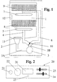
- Fig. 1 illustrates in a schematic way a dishwashing machine according to the present invention.
- reference 1 indicates the washing chamber of the machine, being equipped with a lower collecting sump, indicated with 2; reference 3 indicates a washing pump or circulation pump, having a suitable electric motor, being commonly known.
- Reference 3A indicates the suction branch of the above pump, which draws out washing liquid from the sump 2; the pump 3 forces then the washing liquid, through its delivery branch 3B, into an hydraulic circuit comprising a first branch 4 for supplying a lower sprayer 5 and a second branch 6 for supplying an upper sprayer 7; the baskets 8 and 9 rest in a known way over each sprayer.
- Reference 10 indicates a flow deflector, of the known type, which is located between the inlets of the two branches 4 and 6, and is appropriately controlled by the machine control system, as it will become apparent later.
- the flow deflector 10 is capable of assuming at least two different alternative operating conditions, in particular:
- the flow deflector 10 can be controlled by the machine control system to ensure alternate supply to the sprayers 5 and 7.
- Reference 11 indicates a heating element for the washing liquid and reference number 12 indicates a detergent dispensing device, both being of known manufacture and operation.
- reference 20 indicates as a whole the control panel of the dishwasher shown of Fig. 1, located in the front upper part of the machine cabinet.
- the panel 20 comprises a main on/off switch of the machine, indicated with 21, whereas 22 indicates a knob for selecting a washing cycle among a range of possible cycles, such as for example a soaking cycle (i.e. a simple rinsing of the crockery in order to postpone a real proper washing to a later time), a standard cycle, an intensive cycle, a short cycle.
- a soaking cycle i.e. a simple rinsing of the crockery in order to postpone a real proper washing to a later time
- a standard cycle i.e. a simple rinsing of the crockery in order to postpone a real proper washing to a later time
- an intensive cycle i.e. a simple rinsing of the crockery in order to postpone a real proper washing to a later time
- Reference 23 indicates a push-button for starting the program, which is used for starting the washing cycle previously selected with the knob 22.
- References 24 and 25 indicate two slider selectors, of the known type, for the independent selection of the pressure of the jets delivered by the sprayer 5 and sprayer 7, respectively; in the given example, selectors 24 and 25 are provided to set the washing power of the crockery contained in the baskets 8 and 9, which is obtained adjusting the r.p.m. value of the motor of the pump 3.
- selectors 24 and 25 are provided to supply the machine control system with primary information, i.e. indicating the type of crockery, based on which the control system self-adjusts the washing pressure or power for the sprayers.
- primary information i.e. indicating the type of crockery
- each selector can provide information relating to the following types of crockery: very delicate crockery, delicate crockery, standard crockery, resistant crockery.
- reference 26 indicates a visualizing device or display, such as a liquid crystals display, apt to highlight information of different nature, such as the names of the operating programs that have been selected and/or can be selected by the knob 22 and some operating parameters of the machine, such as the water hardness degree detected in a known way, the residual duration time of a washing cycle, the suggested amount of detergent, and so on.
- a visualizing device or display such as a liquid crystals display
- Fig. 3 illustrates schematically a portion of the control system of the dishwashing machine according to the present invention.
- such a control system is of the electronic type comprising a microcontroller, indicated schematically with MC.
- This microcontroller MC has appropriate memory means, wherein the various operating programs of the dishwashing machine are codified, as well as the instructions required for performing the various functions that the latter is able to carry out.
- the two selectors 24 and 25 are connected to appropriate inputs of the microcontroller MC through known ways and means.
- a first and a second output of the microcontroller MC are provided for the control of the operation of the flow deflector 10 and the display 26, according to known procedures and means.
- a third and a fourth output of the microcontroller MC are provided for the control of the heating element 11 and the detergent dispensing device 12 according to known procedures and means.
- a fifth output of the microcontroller MC is connected, with known procedures and means, to a circuit indicated as a whole with CC, for controlling the speed of the motor of the pump 3.
- This control circuit may be of any known type; for example it can be realized in accordance with the techniques described in the above documents IT-B-1.273.149 and IT-U-TO94U000053, the contents of which are herein incorporated by reference.
- the circuit CC comprises a speedometer dynamo, indicated with DT, apt to detect the actual number of revolutions of the motor of the pump 3; said speedometer dynamo DT is connected with known procedures and means to an appropriate input of the microcontroller MC.
- circuit CC The function of the circuit CC can be explained quite schematically as follows, with reference to a washing cycle with alternate water supply to the sprayers.
- the speedometer dynamo DT is apt to generate a control signal which is proportional to the actual number of revolutions of the motor of the pump 3, which signal is sent to the microcontroller MC.
- This signal is elaborated by the microcontroller itself, by a comparison, at different times, with a first and a second reference signal, relating to the number of revolutions the motor should perform for obtaining the desired washing power for the sprayers 5 and 7, respectively.
- the above reference signals can be obtained using any known technique (see for instance the description of IT-B-1.273.149) and are obviously a function of the setting operated on selectors 24 and 25.
- the microcontroller MC Following a comparison with the first reference signal, the microcontroller MC generates a driving signal of the circuit CC, which makes the motor of the pump 3 to reach and maintain the number of revolutions to the value being required to perform the desired treatment of the contents of the basket 8, set through the selector 24.
- the microcontroller MC provides instead to compare the control signal of the speedometer dynamo DT with the second reference signal; then the microcontroller MC generates a new driving signal of the circuit CC, which will consequently provides for reaching and maintaining the number of revolutions of the motor of the pump 3 to the value being required for performing the desired treatment of the contents of the basket 9, set through the selector 25.
- the dishwashing machine according to the present invention operates as follows.
- the user After loading the glasses in the basket 9 and the pots in the basket 8, the user selects the desired washing program with the knob 22; to do this, the user is eventually aided by the instructions highlighted on the display 26 by the machine control system.
- the microcontroller MC can be programmed to highlight appropriate indications and/or advice for the user on the display 26, according to the settings of the selectors 24 and/or 25.
- the user will select, by the selector 25, a reduced washing power for the contents of the basket 9 and, by the selector 24, a higher washing power for the contents of the basket 8.
- the user can start the washing cycle previously selected, by pressing the push-button 23.
- the microcontroller MC controls the execution of the washing cycle, comprising its usual phases, such as a cold pre-washing phase, a hot washing phase, a hot rinsing phase, a cold rinsing phase, and so on; to this purpose, the microcontroller MC will use the program data coded in its own memory means.
- each phase of the cycle step starts with a supply in the chamber 1 of the required quantity of water, as detected in a known way (for example by means of a pressure switch).
- the microcontroller MC activates the circulation pump 3 and supplies its motor through the circuit CC.
- the flow deflector 10 is in the position shown in Fig. 1, i.e. the closed position of the supply branch 4 of the lower sprayer 5.
- the microcontroller MC After starting the pump 3, the microcontroller MC receives the relevant control signal from the speedometer dynamo DT, which changes with the increasing number of revolutions of the motor 3.
- the microcontroller MC drives the circuit CC to maintain constant the reached number of revolutions.
- washing liquid is forced by the pump into the branch 6 only, and the jets of the sprayer 7 are sprayed at a first pressure.
- the pre-washing phase will go on in this way for a certain time, e.g. a few minutes, and be stopped by deactivation of the motor of the pump 3, performed by the microcontroller MC through the circuit CC.
- the microcontroller MC controls the flow deflector 10 to pass over to the position illustrated by the dotted line of Fig. 1, i.e. to close the branch 6 supplying the upper sprayer 7. Subsequently, the motor of the pump 3 is started again by the microcontroller MC, through the circuit CC.
- the microcontroller MC After the new start of the motor, the microcontroller MC receives the relevant control signal from the speedometer dynamo DT, which varies with the increasing number of revolutions of the motor.
- the microcontroller MC drives the circuit CC in order to maintain constant the reached number of revolutions.
- the treatment of the crockery contained in the basket 8 requires a higher washing power than the previous one, so that the number of revolutions of the motor of the pump 3 must be sufficiently high.
- wash liquid is forced by the pump into the branch 4 only and the jets of the sprayer 5 are delivered at a second pressure, differing from the pressure previously used for treating the contents of the basket 9.
- the washing cycle will go on in this way for a certain time, e.g. a few minutes, and be stopped by deactivation of the pump motor 3. Then the cycle can proceed further discharging the washing liquid from the chamber 1, followed by a new water supply from the mains, to perform a subsequent phase.
- the microcontroller MC will activate the heater 11 after the supply of the required quantity of water in the chamber 3, until the desired temperature (detected in a known way) is reached; similarly, in the event of treatment phases requiring a washing agent dissolved in the water, the microcontroller MC will activate the dispensing device 12, to release the required amount of detergent.
- the different positions of the flow deflector 10 can match different washing powers for the two sprayers.
- the machine control system will appropriately "synchronize" the achievement of the two different washing powers, set by the selectors 24 and 25, with the variation of the working position of the flow deflector 10.
- the above system can also be advantageously used for performing a "reduced" washing program, i.e. using one basket only containing the crockery to be washed, and supplying the sprayer relating to the basket in use.
- the duly programmed microcontroller MC detects the instructions inserted by the user, by verifying the positions set on the selectors 24 and 25.
- the microcontroller MC will be informed by the zero position of the selector 24 that the user intends to perform a washing using only the upper basket 9, and instruct the flow deflector 10 to go over to the closed position of the branch 4; this closed position will be maintained for the whole duration of the selected washing cycle.
- the microcontroller MC will control the circuit CC as per the procedures previously described, and have the motor of the pump 3 reaching and maintaining only one speed for the whole washing cycle duration, i.e. the speed required to obtain the washing power set through the selector 25 from the sprayer 7.
- this capability can be offered by using one selector only, for a determined sprayer, while the adjustment of the pressure relating to the other sprayer is provided by the program data of the machine control system.
- the machine is fitted for example with the selector 25 only, for adjusting the washing power of the upper sprayer 7.
- the user will select a washing cycle with the knob 22, for example the standard cycle, and set a determined washing power with the selector 25 for the sprayer 7, which is here supposed to be different from the washing power established by the program data related to the standard cycle.
- the reference signal (to be compared with the value of the signal coming from the speedometer dynamo DT) relating to the speed the motor of the wash pump 3 should reach for performing the treatment of the contents of the basket 8, will be imposed by the microcontroller MC, according to the stored program data, relating to the standard cycle.
- the reference signal for the speed the motor of the wash pump 3 should have to perform the treatment of the contents of the basket 9 will be determined on the basis of the position of the selector 25, as previously described.
- the setting is allowed of the power or pressure of exit of the jets delivered by one of the sprayers, in an independent and selective manner compared to the power or pressure of exit of the jets of the other sprayer.
- the selector or selectors employed may provide for a high number of selecting positions, which is by far higher than the previous one indicated in the example, for allowing a most accurate and variable setting according to the type of crockery to be washed in each basket.
- the machine control system can also be programmed to perform the treatment of the contents of the two baskets with different temperatures of the washing liquid, always depending on the choices operated with the selecting means 24 and 25.
- washing of the crockery is obtained by means of a chemical action (determined by the presence of detergent in the washing liquid), a thermal action (determined by the temperature of the washing liquid) and a mechanical action (determined by the power of the washing jets), for the treatment of the pots it will be preferable to use not only a significant pressure of the jets from the sprayer 5, but also a higher temperature of the washing liquid than required for washing the porcelain dishes contained in the upper basket 9.
- the microcontroller MC is programmed for heating through the heater 11 at the beginning of the hot washing phase the liquid supplied to the tub, up to a first temperature, such as 45°C.
- the microcontroller MC controls the positioning of the deflecting device 10, for closing the supply branch 6 of the upper sprayer 7; then it will start the pump 3, whose speed is set according to the above procedures.
- the liquid sprayed by the upper sprayer 7 will have a first preset pressure and a first preset temperature.
- the microcontroller MC will stop operation of the pump 3 and control the deflecting device 10 to close the branch 6 supplying the upper sprayer 7; the microcontroller MC will also activate the heating element 11 to bring the washing liquid to a second higher temperature than the previous one, such as 60°C.
- the microcontroller MC Upon reaching said second temperature, the microcontroller MC starts the pump 3, whose speed will be determined as previously described, to obtain a higher washing power than the previous one.
- the liquid sprayed by the lower sprayer 5 will have a second preset pressure and a second preset temperature.
- the machine control system can also be advantageously programmed for optimizing the dispensing times and/or quantities of detergent in function of the type of crockery contained in each basket.
- the detergent dispensing device 11 can be of the type able to contain a plurality of doses of detergent, which can be dispensed in sequence at different times under control of the machine programmer (a detergent dispenser structured as above is described for example in FR-A-2.593.697).
- the microcontroller MC controls the position of the deflecting device 10 for determining the closure of the supplying branch of the lower sprayer 5, and then start the pump 3, whose speed will be determined according to the above procedures; eventually, also the temperature of the washing liquid can be determined as above.
- the microcontroller will also instruct the detergent dispenser 12 to perform the dispensing of a first detergent dose.
- the liquid sprayed by the upper sprayer 7 will contain a first amount of dissolved detergent and be sprayed with a first predetermined pressure; also the temperature of the washing liquid can have a first level, as said above.
- the microcontroller MC will stop operation of the pump 3 and instruct the deflecting device 10 to close the supply branch 6 of the sprayer 7; then the microcontroller MC controls the detergent dispenser 11 to perform the dispensing of a second amount of detergent, to be added to the one already being contained in the washing liquid.
- the microcontroller MC will start the pump 3, whose speed is determined as per the procedures previously described, obtaining a higher washing power than the previous one.
- the liquid sprayed by the lower sprayer 5 will have a second predetermined pressure and a second amount of detergent dissolved in it, which is higher than the previous one; as said, by actuating the heater 11 again, also the temperature of the washing liquid can have a second level, as described above.
- control system of the dishwashing machine can be easily programmed to submit the contents of the upper basket 9 to a time of treatment differing from the time of treatment for the contents of the lower basket 5.
- the microcontroller MC will perform for example the cold pre-washing of the contents of the basket 9 for two minutes, maintaining during this period the deflecting device in the position illustrated in Fig. 1; vice-versa, the cold pre-washing for the contents of the basket 5 will last four minutes, by maintaining during this period the deflecting device in the position illustrated by the dotted line in Fig. 1.
- the present invention offers a considerable flexibility of use for the dishwashing machine, since the user is free to change the type of washing of a specific sprayer, in particular by setting the pressure and/or the temperature and/or the detergent concentration of the liquid sprayed by one sprayer independently from the other sprayer.
- the machine according to the present invention is easy to use and easy to be programmed by the user.
- the components being required for manufacturing the dishwashing machine according to the present invention have a simple design, high reliability and a low cost, as well as the programming of the machine control system, in this frame it should also be noticed that an excellent method for the compact coding of the instructions being required for the operation of the dishwashing machine according to the present invention is the control technology based on fuzzy logic, by now widely utilized in the consumers' applications field, in particular for household electric appliances. Obviously, nothing hinders the use of other programming techniques, such as the tabular method.
- the adjustment of the washing power of the sprayer 5 and 7 is obtained actuating the circulation pump 3 with appropriate speed.
- the system for adjusting the speed of the motor of the pump 3 can be simplified with respect to the one described above.
- the motor of the pump 3 may be for example of the a two-pole asynchronous single-phase type, with a main winding and an auxiliary winding; should a higher washing power be required, both said windings would be inserted to let the pump reach a determined maximum speed; vice-versa, should the washing require a lower washing power, one of the two windings would be deactivated, with a consequent reduction of the maximum possible speed for the motor, and consequently of the liquid pressure and flow rate in the branch 4 or 6 of interest.
- the speed of interest of the pump 3 will be set by the selectors 24 and 25, which are indicative of the type of crockery contained in the baskets 8 and 9.
- the liquid pressure and the flow-rate in the two branches 4 and 6 may also be adjusted using a known shutter, instead of a flow deflector, i.e. a device having a plugging element capable of assuming a plurality of intermediate working positions, instead of just a simple closing position of the branches 4 or 6.
- the adjustment of the washing power is obtained by adequately shuttering the liquid flow circulated by the pump 3, i.e. providing an appropriate "choke” in the hydraulic circuit, to cause a change of the liquid flow-rate supplied to a machine sprayer.
- the machine control system will be programmed for controlling an electric or thermo-electric actuator of the shuttering device, in function of the settings made with the selection means 24 and 25, so as to have a shutter differently positioned depending on the basket 5 or 7 to be prayed during the phase under consideration.
- control system of the machine will also be programmed for selecting, for example according to the procedure already described above, a "reduced" washing cycle, i.e. using only one basket containing all the crockery to be washed, and supplying only the sprayer associated to the basket in use.
- the microcontroller MC will obviously control the shuttering device in order that its shutter fully closes one of the two supply branches, so that the whole washing liquid is conveyed from the pump 3 to one sprayer only.
- the machine control system in function of the choices operated by the user on the selecting means 24 and 25, the machine control system will determine both the motor speed of the pump 3 and the position of the shutter of the shuttering device, whereas in the second event, the control system will only control the shutter positioning.
- the possibility is cited of equipping the machine with appropriate control means, for excluding the alternate washing function, in order to let the user to treat the crockery contained in both baskets 8 and 9 with the same washing pressure or power, determined in an autonomous way by the machine control system, based on the data stored in it.
- control panel 20 may be fitted for example with a proper additional key, for the exclusion of the above function; as an alternative, the machine control system may be programmed to detect the exclusion of the above function from the zero positioning of both selectors 24 and 25.
- the setting of the washing cycle can be performed with the knob 22, and on the basis of the program data of the microcontroller MC, which will also provide to position the deflector or shutter for having both the sprayers 5 and 7 supplied with the same flow-rate of liquid.
- the selectors 24 and 25 are not hindered on a same position.
- the machine according to the present invention is equipped with a shuttering device of the previously mentioned type, for performing diversified washings on both baskets while supplying both sprayers simultaneously, but with a different pressure or diversified flow rates.
- a certain position of the shutter therefore determines simultaneously the liquid flow-rate to be supplied to the branch 4 and the liquid flow-rate to be supplied to the branch 6.
- the present invention has been previously described with reference to a dishwashing machine equipped with an electronic programmer, i.e. using a microcontroller; however it is clear for the man skilled in the art that the invention may also apply to dishwashing machines fitted with an electromechanical programmer.
- setting means 24 and 25 can be replaced with rotary knobs or keys, instead of cursor selectors, and the microcontroller MC can be programmed accordingly for highlighting the possible selections directly on the display 26.
- a proper sort of menu could be provided, being highlighted by the display 26, comprising a set of options the user can select by means of scrolling and confirming keys.
- the display 26 may highlight in its upper part and lower part a set of symbols being representative of the possible pressure adjustments for the upper sprayer and lower sprayer, respectively; in this event, the microcontroller MC is also programmed to highlight on the display 26 an appropriate pointer, sequentially movable on the above symbols in function of the pressure exerted on the respective input keys.
- the washing program can be started by pressing the button 23. The same procedure may be followed to set the duration of the diversified washing cycles or for the temperatures selection.
- a further possible variant embodiment provides only one selector or control means, instead of the two previously indicated with 24 and 25, for setting the washing power desired for each basket.
- the sole selector provided can be combined with a confirmation key and the microcontroller MC can be programmed to highlight sequentially on the display 26 which type of crockery is contained in each basket. Therefore, following a request concerning the basket 8, the user will bring the selector to the desired position and press the confirmation button; then the request concerning the basket 9 will follow, and also in this case the user has to press the confirmation button after bringing the selector to the desired position.
- the machine control system can also be programmed, in a known way for
- the microcontroller MC will be programmed to control, through the heater 11, the heating of the washing liquid at the optimal temperature for the treatment of the delicate crockery (for example 50°C), which is in any case also used for washing the pots, through the alternation of the supply of the sprayers 7 and 8.
- the machine control system always in function of the instructions supplied by the selectors 24 and 25, can provide to automatically change other variables of the cycle, such as the number of phases and/or the treatment times of the contents of the two baskets; this in view of the fact that the washing the pots contained in the lower basket 8 will necessarily require a more intensive treatment; accordingly, the machine control system can, for example, add a rinsing phase to the cycle for the crockery contained in the basket 8, which require a stronger treatment.
- Another variant embodiment should different temperatures and/or detergent dosages be chosen for the two sprayers to be supplied, may consist in carrying out a complete washing phase of the contents of a first basket, the discharge of the washing liquid used and the subsequent supply of new clean water, to be heated and/or complemented with the amount of detergent suitable for washing the crockery contained in the second basket.
Abstract
- the pressure of the liquid sprayed by each sprayer and/or
- the temperature of the liquid sprayed by each sprayer, and/or
- the amount of detergent dissolved in the liquid sprayed by each sprayer, and/or
- the duration of the single spraying phases of the crockery for each basket.
Description
- The present invention refers to a household dishwashing machine.
- As known, household dishwashing machines generally comprise a box-type structure defining a washing chamber, wherein an upper loading basket and a lower loading basket are housed, for containing the crockery to be washed.
- Below each loading basket, a spraying element is provided, rotating around a substantially vertical axis, which hits the crockery placed in the overhanging basket with a plurality of washing liquid jets; to this purpose, a special circulation pump actuated by an electric motor supplies pressurized liquid to the sprayers.
- According to some known solutions, the hydraulic circuit of the dishwashing machine is designed for performing the execution of a washing cycle by supplying with water one sprayer only or by supplying with water both sprayers in an alternate way.
- The first solution is typical for those cases where the dishwashing machine should be able to perform a so-called "half load" washing program, i.e. when only one basket is used, containing a restricted number of crockery items, and only the sprayer associated to the basket in use has to be supplied with the washing liquid. An embodiment of this type is known for example from the document EP-A-0 772 995.
- The second cited solution, relating to the alternate supply of the sprayers, is presently spreading out for dishwashing machines and has essentially the aims of:
- allowing the use of only one circulation pump for both sprayers, with an electric motor of relatively small dimensions (it is clear, in fact, that if the pump has to supply water to two sprayers simultaneously, its motor must have a higher power, and consequently larger dimensions);
- reducing noisiness of the machine in operation, which is caused by the impact of the liquid jets from the sprayers against the wash-tub walls;
- saving water and power consumption to a certain extent.
- Examples of dishwashing machines having an alternate water supply to the sprayers are described in FR-A-2.505.643, EP-A-237.994, FR-A-2.443.231.
- In general, in the above first solution, an intercepting device is provided, for the washing liquid flow, coming from the circulation pump and directed to one of the two supply branches of the sprayers; this intercepting device, appropriately controlled by the machine control system, keeps the above branch of the hydraulic circuit constantly closed, so that only the sprayer associated to the basket actually in use receives the liquid. for the whole duration of the washing program.
- In the second solution, vice-versa, a flow deflector is provided, apt to convey the liquid alternatively to one of the above two branches; in this case, the machine control system instructs the flow deflecting device to open and close both branches of the hydraulic circuit, in alternate sequences; thus, the washing cycle is performed with alternate water supply to the upper and lower sprayer with the liquid at a preset temperature, wherein a certain amount of detergent is dissolved.
- It is also known that, in order to efficiently wash pots and pans or other very dirty crockery, a considerable pressure of the washing liquid is required; consequently, the electric motor actuating the circulation pump should practically operate at its maximum power.
- On the contrary, in order to wash fragile crockery items, such as crystal glasses or porcelains, it is advisable to use a lower pressure than usual, to avoid that the power of the liquid jets from the sprayers may cause damages to the crockery, such as breakage or splitting.
- Based on the above consideration, household dishwashing machines have been developed. which allow to change the pressure of the washing water to both sprayers.
- These solutions, known from example from the documents IT-B-1.273.149 and IT-U-TO94U000053, provide for the intervention with appropriate control means on the electric motor of the circulation pump, to change the number of revolution, or r.p.m. value, in function of the desired pressure.
- However, washing machines equipped with an r.p.m. adjusting system of the pump motor as mentioned in the above Italian documents, offer little flexibility as a whole.
- In fact, if the user, on one hand, has the capability of selecting in a simple and accurate way the desired washing power, on the other hand, the user is compelled to wash crockery items having substantially homogeneous hardiness features; in other words, the user should only load in the dishwasher fragile crockery items requiring a relatively low pressure of the washing liquid or, alternatively, only standard or resistant crockery items, which can be washed at higher pressures.
- Another problem of the prior art relates to the fact that to the treatment of different crockery items contained in the two baskets is anyway practically performed with a liquid having the same temperature and same amount of dissolved detergent, also in the instance of alternate washing; also the times of spraying both baskets do not change from each other, independently from their crockery contents. In other words, known dishwashing machines do not allow for obtaining a real diversified treatment of the contents of both baskets during one same operating cycle.
- The present invention has the aim of solving the above drawbacks of the prior art and providing a dishwashing machine comprising at least two sprayers, in which the capability is offered to the user of changing, in an easy and simple manner, one or more characteristics of the liquid flow exiting said sprayers, eventually also in an independent way from each other.
- Within this general frame, a first aim of the present invention is that of providing a dishwashing machine which allows for the selection of diversified washing powers for the two sprayers.
- A second aim of the present invention is that of providing a dishwashing machine which allows for spraying, from a first sprayer, a liquid having a different temperature with respect to the liquid sprayed from a second sprayer.
- A third aim of the present invention is that of providing a dishwashing machine which allows for spraying, from a first sprayer, a liquid having a different amount of dissolved detergent with respect to the liquid sprayed from a second sprayer.
- A fourth aim of the present invention is that of providing a dishwashing machine in which, in the course of a same operating cycle, the duration of the treatment of the contents of a first basket can be different from the duration of the treatment of the contents of a second basket.
- A further aim of the present invention is that of providing such a dishwashing machine which, though having a high versatility of use, is easy to use and to program by a user.
- A further aim of the present invention is that of providing such a dishwashing machine which has a low manufacturing cost and uses simple, cost effective and reliable components.
- One or more of said aims are reached, according to the present invention, by a dishwashing machine incorporating the features of the annexed claims, which form an integral part of the present description.
- Aims, features and advantages of the present invention will become apparent from the following detailed description and annexed drawings, which are supplied by way of non limiting example, wherein:
- Fig. 1 shows a schematic section of a dishwashing machine, according to the present invention;
- Fig. 2 shows schematically the control panel of the dishwashing machine represented in Fig. 1;
- Fig. 3 shows schematically a portion of the control system of the machine represented in Fig. 1.
- Fig. 1 illustrates in a schematic way a dishwashing machine according to the present invention.
- In this figure,
reference 1 indicates the washing chamber of the machine, being equipped with a lower collecting sump, indicated with 2;reference 3 indicates a washing pump or circulation pump, having a suitable electric motor, being commonly known. -
Reference 3A indicates the suction branch of the above pump, which draws out washing liquid from thesump 2; thepump 3 forces then the washing liquid, through itsdelivery branch 3B, into an hydraulic circuit comprising afirst branch 4 for supplying alower sprayer 5 and asecond branch 6 for supplying anupper sprayer 7; thebaskets -
Reference 10 indicates a flow deflector, of the known type, which is located between the inlets of the twobranches flow deflector 10 is capable of assuming at least two different alternative operating conditions, in particular: - a closure condition of the
branch 4, being represented in Fig. 1, with simultaneous opening of thebranch 6; - a closure condition of the
branch 6, being indicated by the dotted line in Fig. 1, with simultaneous opening of thebranch 4. - The
flow deflector 10 can be controlled by the machine control system to ensure alternate supply to thesprayers -
Reference 11 indicates a heating element for the washing liquid andreference number 12 indicates a detergent dispensing device, both being of known manufacture and operation. - In Fig. 2
reference 20 indicates as a whole the control panel of the dishwasher shown of Fig. 1, located in the front upper part of the machine cabinet. - The
panel 20 comprises a main on/off switch of the machine, indicated with 21, whereas 22 indicates a knob for selecting a washing cycle among a range of possible cycles, such as for example a soaking cycle (i.e. a simple rinsing of the crockery in order to postpone a real proper washing to a later time), a standard cycle, an intensive cycle, a short cycle. -
Reference 23 indicates a push-button for starting the program, which is used for starting the washing cycle previously selected with theknob 22. -
References sprayer 5 andsprayer 7, respectively; in the given example,selectors baskets pump 3. - Proper indications for the user are associated to the various positions that can be taken by the
selectors relevant basket - Therefore,
selectors - Finally,
reference 26 indicates a visualizing device or display, such as a liquid crystals display, apt to highlight information of different nature, such as the names of the operating programs that have been selected and/or can be selected by theknob 22 and some operating parameters of the machine, such as the water hardness degree detected in a known way, the residual duration time of a washing cycle, the suggested amount of detergent, and so on. - Fig. 3 illustrates schematically a portion of the control system of the dishwashing machine according to the present invention.
- In the example, such a control system is of the electronic type comprising a microcontroller, indicated schematically with MC.
- This microcontroller MC has appropriate memory means, wherein the various operating programs of the dishwashing machine are codified, as well as the instructions required for performing the various functions that the latter is able to carry out.
- As it can be seen, the two
selectors - A first and a second output of the microcontroller MC are provided for the control of the operation of the
flow deflector 10 and thedisplay 26, according to known procedures and means. - A third and a fourth output of the microcontroller MC are provided for the control of the
heating element 11 and thedetergent dispensing device 12 according to known procedures and means. - A fifth output of the microcontroller MC is connected, with known procedures and means, to a circuit indicated as a whole with CC, for controlling the speed of the motor of the
pump 3. - This control circuit may be of any known type; for example it can be realized in accordance with the techniques described in the above documents IT-B-1.273.149 and IT-U-TO94U000053, the contents of which are herein incorporated by reference.
- In this connection it is pointed out that in the example of the figure, the circuit CC comprises a speedometer dynamo, indicated with DT, apt to detect the actual number of revolutions of the motor of the
pump 3; said speedometer dynamo DT is connected with known procedures and means to an appropriate input of the microcontroller MC. - The function of the circuit CC can be explained quite schematically as follows, with reference to a washing cycle with alternate water supply to the sprayers.
- The speedometer dynamo DT is apt to generate a control signal which is proportional to the actual number of revolutions of the motor of the
pump 3, which signal is sent to the microcontroller MC. This signal is elaborated by the microcontroller itself, by a comparison, at different times, with a first and a second reference signal, relating to the number of revolutions the motor should perform for obtaining the desired washing power for thesprayers - The above reference signals can be obtained using any known technique (see for instance the description of IT-B-1.273.149) and are obviously a function of the setting operated on
selectors - Following a comparison with the first reference signal, the microcontroller MC generates a driving signal of the circuit CC, which makes the motor of the
pump 3 to reach and maintain the number of revolutions to the value being required to perform the desired treatment of the contents of thebasket 8, set through theselector 24. - At a subsequent time during the washing cycle, the microcontroller MC provides instead to compare the control signal of the speedometer dynamo DT with the second reference signal; then the microcontroller MC generates a new driving signal of the circuit CC, which will consequently provides for reaching and maintaining the number of revolutions of the motor of the
pump 3 to the value being required for performing the desired treatment of the contents of thebasket 9, set through theselector 25. - The dishwashing machine according to the present invention operates as follows.
- Let us assume, to this purpose, that the user wishes to wash very fragile crockery, such as crystal glasses, along with resistant crockery, such as very dirty pots and pans, at the same time.
- After loading the glasses in the
basket 9 and the pots in thebasket 8, the user selects the desired washing program with theknob 22; to do this, the user is eventually aided by the instructions highlighted on thedisplay 26 by the machine control system. - Then the user indicates the type of crockery contained in the
baskets selectors display 26, according to the settings of theselectors 24 and/or 25. - By so doing, therefore, the user will select, by the
selector 25, a reduced washing power for the contents of thebasket 9 and, by theselector 24, a higher washing power for the contents of thebasket 8. - After this operation, the user can start the washing cycle previously selected, by pressing the push-
button 23. - The microcontroller MC controls the execution of the washing cycle, comprising its usual phases, such as a cold pre-washing phase, a hot washing phase, a hot rinsing phase, a cold rinsing phase, and so on; to this purpose, the microcontroller MC will use the program data coded in its own memory means.
- In general, each phase of the cycle step starts with a supply in the
chamber 1 of the required quantity of water, as detected in a known way (for example by means of a pressure switch). - Once the volume of water required for the pre-washing phase has been supplied from the water mains, the microcontroller MC activates the
circulation pump 3 and supplies its motor through the circuit CC. - In this situation, the
flow deflector 10 is in the position shown in Fig. 1, i.e. the closed position of thesupply branch 4 of thelower sprayer 5. - After starting the
pump 3, the microcontroller MC receives the relevant control signal from the speedometer dynamo DT, which changes with the increasing number of revolutions of themotor 3. - When the above control signal from the dynamo DT matches the reference signal determined by the setting of the
selector 25, the microcontroller MC drives the circuit CC to maintain constant the reached number of revolutions. - As said above, a low washing power is required to wash the crockery contained in the
basket 9; therefore, the number of revolutions of the motor of thepump 3 will be relatively low. - Thus, the washing liquid is forced by the pump into the
branch 6 only, and the jets of thesprayer 7 are sprayed at a first pressure. - The pre-washing phase will go on in this way for a certain time, e.g. a few minutes, and be stopped by deactivation of the motor of the
pump 3, performed by the microcontroller MC through the circuit CC. - A few instants after the interruption, the microcontroller MC controls the
flow deflector 10 to pass over to the position illustrated by the dotted line of Fig. 1, i.e. to close thebranch 6 supplying theupper sprayer 7. Subsequently, the motor of thepump 3 is started again by the microcontroller MC, through the circuit CC. - After the new start of the motor, the microcontroller MC receives the relevant control signal from the speedometer dynamo DT, which varies with the increasing number of revolutions of the motor.
- When the control signal received from the dynamo DT matches the reference signal determined by the setting of the
selector 24, the microcontroller MC drives the circuit CC in order to maintain constant the reached number of revolutions. - As said above, the treatment of the crockery contained in the
basket 8 requires a higher washing power than the previous one, so that the number of revolutions of the motor of thepump 3 must be sufficiently high. - Thus, the wash liquid is forced by the pump into the
branch 4 only and the jets of thesprayer 5 are delivered at a second pressure, differing from the pressure previously used for treating the contents of thebasket 9. - The washing cycle will go on in this way for a certain time, e.g. a few minutes, and be stopped by deactivation of the
pump motor 3. Then the cycle can proceed further discharging the washing liquid from thechamber 1, followed by a new water supply from the mains, to perform a subsequent phase. - Obviously, if case of hot treatment phases, the microcontroller MC will activate the
heater 11 after the supply of the required quantity of water in thechamber 3, until the desired temperature (detected in a known way) is reached; similarly, in the event of treatment phases requiring a washing agent dissolved in the water, the microcontroller MC will activate the dispensingdevice 12, to release the required amount of detergent. - Anyway, apart from the liquid temperature and the likely presence of the detergent in the latter, the further phases of the washing cycle will be performed according to the above procedures, i.e. by the alternate supply and the diversified pressures/powers for the two
sprayers - From the above it can be noticed how, according to the present invention, the different positions of the
flow deflector 10 can match different washing powers for the two sprayers. - To this purpose, the machine control system will appropriately "synchronize" the achievement of the two different washing powers, set by the
selectors flow deflector 10. - The above system can also be advantageously used for performing a "reduced" washing program, i.e. using one basket only containing the crockery to be washed, and supplying the sprayer relating to the basket in use.
- This can be obtained quite easily, with an appropriate programming of the microcontroller
- MC, providing respective zero or disabled positions for the
selectors - Let us assume, for example, that the user has to perform a quick wash of a small quantity of fairly dirty porcelain crockery. To this purpose the user has to:
- load the crockery in the
upper basket 9 only; - select with the
knob 22 the short washing cycle; - select the desired washing power with the
selector 25; - take the
selector 24 to its zero position; - start the washing cycle pressing the push-
button 23. - The duly programmed microcontroller MC detects the instructions inserted by the user, by verifying the positions set on the
selectors - In the specific event, the microcontroller MC will be informed by the zero position of the
selector 24 that the user intends to perform a washing using only theupper basket 9, and instruct theflow deflector 10 to go over to the closed position of thebranch 4; this closed position will be maintained for the whole duration of the selected washing cycle. - Based on the same information derived from the zero position of the
selector 24, the microcontroller MC will control the circuit CC as per the procedures previously described, and have the motor of thepump 3 reaching and maintaining only one speed for the whole washing cycle duration, i.e. the speed required to obtain the washing power set through theselector 25 from thesprayer 7. - The above description with reference to the
sprayer 7 applies of course also to thesprayer 5, since the user has the possibility of performing washing of a restricted quantity of crockery using eitherbasket - Reference has been previously made to the possibility of setting the washing power independently for both sprayers using two separate selectors.
- However, in a possible variant embodiment of the present invention, this capability can be offered by using one selector only, for a determined sprayer, while the adjustment of the pressure relating to the other sprayer is provided by the program data of the machine control system.
- According to this embodiment, the machine is fitted for example with the
selector 25 only, for adjusting the washing power of theupper sprayer 7. - As described above with reference to the use of the machine, the user will select a washing cycle with the
knob 22, for example the standard cycle, and set a determined washing power with theselector 25 for thesprayer 7, which is here supposed to be different from the washing power established by the program data related to the standard cycle. - After the washing cycle has been started, by pressing the
button 23, the machine will substantially operate as previously described. - However, in this case, the reference signal (to be compared with the value of the signal coming from the speedometer dynamo DT) relating to the speed the motor of the
wash pump 3 should reach for performing the treatment of the contents of thebasket 8, will be imposed by the microcontroller MC, according to the stored program data, relating to the standard cycle. On the contrary, the reference signal for the speed the motor of thewash pump 3 should have to perform the treatment of the contents of thebasket 9 will be determined on the basis of the position of theselector 25, as previously described. - As it can be seen, also according to this embodiment, the setting is allowed of the power or pressure of exit of the jets delivered by one of the sprayers, in an independent and selective manner compared to the power or pressure of exit of the jets of the other sprayer.
- If required, the selector or selectors employed may provide for a high number of selecting positions, which is by far higher than the previous one indicated in the example, for allowing a most accurate and variable setting according to the type of crockery to be washed in each basket.
- According to a possible embodiment of the present invention, the machine control system can also be programmed to perform the treatment of the contents of the two baskets with different temperatures of the washing liquid, always depending on the choices operated with the selecting
means - Let us suppose, for instance, that the
lower basket 8 contains very dirty pots and pans, whereas theupper basket 9 contains valuable porcelain dishes, and the user has consequently set theselector 24 on the "resistant crockery" position andselector 25 on the "delicate crockery" position. - Considering that the washing of the crockery is obtained by means of a chemical action (determined by the presence of detergent in the washing liquid), a thermal action (determined by the temperature of the washing liquid) and a mechanical action (determined by the power of the washing jets), for the treatment of the pots it will be preferable to use not only a significant pressure of the jets from the
sprayer 5, but also a higher temperature of the washing liquid than required for washing the porcelain dishes contained in theupper basket 9. - In such an event, the microcontroller MC is programmed for heating through the
heater 11 at the beginning of the hot washing phase the liquid supplied to the tub, up to a first temperature, such as 45°C. - Upon reaching said first temperature, and after dispensing the detergent by means of the dispensing
device 12, the microcontroller MC controls the positioning of the deflectingdevice 10, for closing thesupply branch 6 of theupper sprayer 7; then it will start thepump 3, whose speed is set according to the above procedures. - Thus, the liquid sprayed by the
upper sprayer 7 will have a first preset pressure and a first preset temperature. - Subsequently, the microcontroller MC will stop operation of the
pump 3 and control the deflectingdevice 10 to close thebranch 6 supplying theupper sprayer 7; the microcontroller MC will also activate theheating element 11 to bring the washing liquid to a second higher temperature than the previous one, such as 60°C. - Upon reaching said second temperature, the microcontroller MC starts the
pump 3, whose speed will be determined as previously described, to obtain a higher washing power than the previous one. Thus, the liquid sprayed by thelower sprayer 5 will have a second preset pressure and a second preset temperature. - The machine control system can also be advantageously programmed for optimizing the dispensing times and/or quantities of detergent in function of the type of crockery contained in each basket.
- Accordingly, the
detergent dispensing device 11 can be of the type able to contain a plurality of doses of detergent, which can be dispensed in sequence at different times under control of the machine programmer (a detergent dispenser structured as above is described for example in FR-A-2.593.697). - In this event, at the beginning of the hot washing phase, the microcontroller MC controls the position of the deflecting
device 10 for determining the closure of the supplying branch of thelower sprayer 5, and then start thepump 3, whose speed will be determined according to the above procedures; eventually, also the temperature of the washing liquid can be determined as above. The microcontroller will also instruct thedetergent dispenser 12 to perform the dispensing of a first detergent dose. - In this way, the liquid sprayed by the
upper sprayer 7 will contain a first amount of dissolved detergent and be sprayed with a first predetermined pressure; also the temperature of the washing liquid can have a first level, as said above. - Subsequently, the microcontroller MC will stop operation of the
pump 3 and instruct the deflectingdevice 10 to close thesupply branch 6 of thesprayer 7; then the microcontroller MC controls thedetergent dispenser 11 to perform the dispensing of a second amount of detergent, to be added to the one already being contained in the washing liquid. - Then the microcontroller MC will start the
pump 3, whose speed is determined as per the procedures previously described, obtaining a higher washing power than the previous one. - In this way, the liquid sprayed by the
lower sprayer 5 will have a second predetermined pressure and a second amount of detergent dissolved in it, which is higher than the previous one; as said, by actuating theheater 11 again, also the temperature of the washing liquid can have a second level, as described above. - Finally, the control system of the dishwashing machine according to the present invention can be easily programmed to submit the contents of the
upper basket 9 to a time of treatment differing from the time of treatment for the contents of thelower basket 5. - This can be obtained by a simple programming of the microcontroller MC which, in function of the position of the selecting
means device 10. In other words, in function of the type of crockery contained in both baskets, the machine control system will maintain, during one or more phases being provided by the machine operating cycle, theflow deflector 10 in the closed position of thesupply branch 4 of thelower sprayer 5 for a time differing from the time during which theflow deflector 10 is maintained in the closed position of thesupply branch 6 of theupper sprayer 7. - As a specific example, let suppose that the
lower basket 8 contains very dirty pots and pans, whereas theupper basket 9 contains valuable porcelain dishes, and the user has set theselector 24 on the "resistant crockery" position andselector 25 on the "delicate crockery" position. - Based on the instructions derived from the position of the selecting
means basket 9 for two minutes, maintaining during this period the deflecting device in the position illustrated in Fig. 1; vice-versa, the cold pre-washing for the contents of thebasket 5 will last four minutes, by maintaining during this period the deflecting device in the position illustrated by the dotted line in Fig. 1. - From the above description it can be seen how, according to the present invention, during one same operating cycle of the machine, differentiated washing programs can be performed for the two baskets, with reference to:
- the pressure of the liquid sprayed by each sprayer, and/or
- the temperature of the liquid sprayed by each sprayer, and/or
- the amount of detergent dissolved in the liquid sprayed by each sprayer, and/or
- the duration of the single spraying phases for the crockery of each basket.
- In other words, therefore, according to the present invention, it is possible to actually change one or more characteristics of the liquid flow delivered by each sprayer, so as to perform diversified washing programs for each basket.
- From the above description the features of the present invention, as well as the advantages thereof, are clear.
- As already mentioned, the present invention offers a considerable flexibility of use for the dishwashing machine, since the user is free to change the type of washing of a specific sprayer, in particular by setting the pressure and/or the temperature and/or the detergent concentration of the liquid sprayed by one sprayer independently from the other sprayer.
- Additionally, the machine according to the present invention is easy to use and easy to be programmed by the user.
- The components being required for manufacturing the dishwashing machine according to the present invention have a simple design, high reliability and a low cost, as well as the programming of the machine control system, in this frame it should also be noticed that an excellent method for the compact coding of the instructions being required for the operation of the dishwashing machine according to the present invention is the control technology based on fuzzy logic, by now widely utilized in the consumers' applications field, in particular for household electric appliances. Obviously, nothing hinders the use of other programming techniques, such as the tabular method.
- It is obvious that many changes are possible for the man skilled in the art to the dishwashing machine described above by way of example, without departing from the novelty spirit of the inventive idea.
- According to the embodiment previously described, the adjustment of the washing power of the
sprayer circulation pump 3 with appropriate speed. However, according to a possible implementation of the present invention, the system for adjusting the speed of the motor of thepump 3 can be simplified with respect to the one described above. - The motor of the
pump 3 may be for example of the a two-pole asynchronous single-phase type, with a main winding and an auxiliary winding; should a higher washing power be required, both said windings would be inserted to let the pump reach a determined maximum speed; vice-versa, should the washing require a lower washing power, one of the two windings would be deactivated, with a consequent reduction of the maximum possible speed for the motor, and consequently of the liquid pressure and flow rate in thebranch - Obviously, also in the case of the simplified variant embodiment herein suggested, the speed of interest of the
pump 3 will be set by theselectors baskets - According to a further variant embodiment, the liquid pressure and the flow-rate in the two
branches branches - Accordingly, the adjustment of the washing power is obtained by adequately shuttering the liquid flow circulated by the
pump 3, i.e. providing an appropriate "choke" in the hydraulic circuit, to cause a change of the liquid flow-rate supplied to a machine sprayer. - In this embodiment, the machine control system will be programmed for controlling an electric or thermo-electric actuator of the shuttering device, in function of the settings made with the selection means 24 and 25, so as to have a shutter differently positioned depending on the
basket - According to the suggested variant, when supplying a specific sprayer, a portion of the washing liquid will anyway also reach the sprayer not involved (i.e. if during a specific phase the shuttering device is positioned to supply the requested washing power to the
sprayer 7, a certain amount of water will also reach the sprayer 5); however, it is clear that also this portion of liquid will anyway contribute to the washing of the crockery in the machine. - Advantageously, the control system of the machine will also be programmed for selecting, for example according to the procedure already described above, a "reduced" washing cycle, i.e. using only one basket containing all the crockery to be washed, and supplying only the sprayer associated to the basket in use.
- In the event of this selection, the microcontroller MC will obviously control the shuttering device in order that its shutter fully closes one of the two supply branches, so that the whole washing liquid is conveyed from the
pump 3 to one sprayer only. - Of course, the described variant embodiment may be applied jointly or optionally to the previously described ones, with reference to the capability of adjusting or changing the number of revolutions of the motor of the
pump 3. - Therefore, in the first instance, in function of the choices operated by the user on the selecting
means pump 3 and the position of the shutter of the shuttering device, whereas in the second event, the control system will only control the shutter positioning. - Among other possible variant embodiments, the possibility is cited of equipping the machine with appropriate control means, for excluding the alternate washing function, in order to let the user to treat the crockery contained in both
baskets - In this frame, the
control panel 20 may be fitted for example with a proper additional key, for the exclusion of the above function; as an alternative, the machine control system may be programmed to detect the exclusion of the above function from the zero positioning of bothselectors - Therefore, in this case, the setting of the washing cycle can be performed with the
knob 22, and on the basis of the program data of the microcontroller MC, which will also provide to position the deflector or shutter for having both thesprayers selectors - In a further simplified variant implementation, the machine according to the present invention is equipped with a shuttering device of the previously mentioned type, for performing diversified washings on both baskets while supplying both sprayers simultaneously, but with a different pressure or diversified flow rates.
- In this application, a certain position of the shutter therefore determines simultaneously the liquid flow-rate to be supplied to the
branch 4 and the liquid flow-rate to be supplied to thebranch 6. - The present invention has been previously described with reference to a dishwashing machine equipped with an electronic programmer, i.e. using a microcontroller; however it is clear for the man skilled in the art that the invention may also apply to dishwashing machines fitted with an electromechanical programmer.
- Of course, the setting means 24 and 25 can be replaced with rotary knobs or keys, instead of cursor selectors, and the microcontroller MC can be programmed accordingly for highlighting the possible selections directly on the
display 26. - Within this frame, in order to insert the data relating to the desired types of washing, a proper sort of menu could be provided, being highlighted by the
display 26, comprising a set of options the user can select by means of scrolling and confirming keys. - For example, the
display 26 may highlight in its upper part and lower part a set of symbols being representative of the possible pressure adjustments for the upper sprayer and lower sprayer, respectively; in this event, the microcontroller MC is also programmed to highlight on thedisplay 26 an appropriate pointer, sequentially movable on the above symbols in function of the pressure exerted on the respective input keys. Once the symbol involved for each sprayer has been selected with the above scrolling keys, the washing program can be started by pressing thebutton 23. The same procedure may be followed to set the duration of the diversified washing cycles or for the temperatures selection. - A further possible variant embodiment provides only one selector or control means, instead of the two previously indicated with 24 and 25, for setting the washing power desired for each basket.
- For instance, the sole selector provided can be combined with a confirmation key and the microcontroller MC can be programmed to highlight sequentially on the
display 26 which type of crockery is contained in each basket. Therefore, following a request concerning thebasket 8, the user will bring the selector to the desired position and press the confirmation button; then the request concerning thebasket 9 will follow, and also in this case the user has to press the confirmation button after bringing the selector to the desired position. - Among other possible implementations, the machine control system can also be programmed, in a known way for
- controlling the heating of the liquid only at the temperature deemed to be optimal for the washing of the most delicate crockery contained in one of the two baskets, and
- eventually changing the treatment cycle in function of the type of crockery contained in the other basket.
- Let us suppose that the
lower basket 8 contains very dirty pots and pans and theupper basket 9 valuable porcelain dishes, and that the user has set theselector 24 on the "resistant crockery" position andselector 25 on the "delicate crockery" position. - According to the suggested variant, the microcontroller MC will be programmed to control, through the
heater 11, the heating of the washing liquid at the optimal temperature for the treatment of the delicate crockery (for example 50°C), which is in any case also used for washing the pots, through the alternation of the supply of thesprayers - In this case, however, the machine control system, always in function of the instructions supplied by the
selectors lower basket 8 will necessarily require a more intensive treatment; accordingly, the machine control system can, for example, add a rinsing phase to the cycle for the crockery contained in thebasket 8, which require a stronger treatment. - Another variant embodiment, should different temperatures and/or detergent dosages be chosen for the two sprayers to be supplied, may consist in carrying out a complete washing phase of the contents of a first basket, the discharge of the washing liquid used and the subsequent supply of new clean water, to be heated and/or complemented with the amount of detergent suitable for washing the crockery contained in the second basket.
Claims (21)
- Household dishwashing machine comprising:characterized in that it also provides for:a control system (MC,CC),a washing chamber (1), wherein at least a first (8) and a second basket (9) are housed, for containing the crockery to be washed,a hydraulic circuit, comprising at least a first and a second liquid sprayer (5,7), a pump (3), a first supply branch (4) for said first sprayer (5) and a second supply branch (6) for said second sprayer (5), where in order to wash the crockery said pump (3) provides for forcing liquid from the bottom of said tub (1) into said supply branches (4,6), for causing a respective liquid flow to exit from each of said sprayers (5,7),detergent dispensing means (12),liquid heating means (11),adjusting means (10) of the amount of liquid forced by said pump (3) into said supply branches (4,6),said selecting means (24,25,26) and said control means (MC,CC) being provided for allowing to perform, during a same operating cycle of the machine, a treatment of the crockery contained in said first basket (8) which is different from the treatment to which the crockery contained in said second basket (9) are subjected to.selecting means (22,24,25,26), for supplying said control system with information being indicative of the type of crockery contained in said first basket (8) and in said second basket (9);control means (MC,CC) which, at least during at least a phase of an operating cycle of the machine, are capable of controlling the liquid flow exiting each sprayer (5,7), in particular for changing one or more characteristics of said flow, in function of said information supplied through said selecting means (24,25),
- Dishwashing machine, according to claim 1, characterized in that said adjusting means comprise a flow deflecting device (10), capable of assuming at least:so that the liquid is alternately forced by said pump (3) into said first branch (4) or said second branch (6).a first operating condition, wherein said first branch (4) is open and said second branch (6) is closed;a second operating condition, wherein said first branch (4) is closed and said second branch (6) is open,
- Dishwashing machine, according to claim 1, characterized in that said adjusting means comprise means for changing the flow-rate of liquid supplied into said first branch (4) with respect to the flow-rate of liquid supplied into said second branch (4), said means for changing the flow-rate being capable of assuming at least:a first operating condition, in which a first flow-rate of liquid is admitted into said first branch (4), being different from the flow-rate of liquid admitted into said second branch (6);a second operating condition, in which a flow-rate of liquid, being different from said first flow-rate, is admitted into said first branch (4).
- Dishwashing machine, according to at least one of the previous claims,
characterized in that said adjusting means (10) are controlled by said control means (MC) in function of said information supplied through said selecting means (24,25). - Dishwashing machine, according to at least one of the previous claims,
characterized in that said control means (MC,CC) are operative for determining the pressure or power of the liquid flow exiting each sprayer (5,7), the liquid flow exiting a sprayer (5) having a different pressure or power with respect to the liquid flow exiting the other sprayer (7). - Dishwashing machine, according to claim 5, characterized in that said control means (MC) provides for controlling a circuit (CC) for adjusting the speed of a motor of said pump (3), in function of said information supplied through said selecting means (24,25), the speed of said pump (3) during said first operating condition being different with respect to the speed of said pump (3) during said second operating condition.
- Dishwashing machine, according to claim 5, characterized in that said control means (MC) provides for controlling said means for changing the flow-rate in function of said information supplied through said selecting means (24,25), so that the flow of liquid exiting said first sprayer (5) has a different pressure or power with respect to the flow of liquid exiting the other sprayer (7).
- Dishwashing machine, according to claim 1 or 2, characterized in that said control means (MC,CC) are operative for determining the temperature of the liquid exiting each sprayer (5,7), said control means (MC) controlling said heating means (12) so that the liquid exiting said first sprayer (5) during said first operating condition has a different temperature with respect to the temperature of the liquid exiting said second sprayer (7) during said second operating condition.
- Dishwashing machine, according to claim 1 or 2, characterized in that said control means (MC,CC) are operative for determining the amount of detergent being present in the flow of liquid exiting each sprayer (5,7), by controlling means (12) for varying the detergent concentration, so that the liquid exiting said first sprayer (5) during said first operating condition has a different detergent concentration with respect to the liquid exiting said second sprayer (7) during said second operating condition.
- Dishwashing machine, according to the previous claim, characterized in that said means (12) for varying the detergent concentration comprise said detergent dispensing means (12).
- Dishwashing machine, according to the previous claim, characterized in that said detergent dispensing means (12) comprise a dispenser apt to contain a plurality of detergent doses, which can be dispensed at different times.
- Dishwashing machine, according to claim 4, characterized in that said control means (MC,CC) are operative for determining the duration of the flow of liquid exiting each sprayer (5,7), whereby the duration of the flow of liquid exiting said first sprayer (5) can be different from the duration of the flow of liquid exiting said second sprayer (7).
- Dishwashing machine, according to claim 4, characterized in that said control means (MC) control the time of maintenance of said first operating condition and said second operating condition in function of said information supplied through said selecting means (24,25).
- Dishwashing machine, according to claim 1, characterized in that said pump (3) comprises a two pole asynchronous single-phase motor, having a main winding and an auxiliary winding.
- Dishwashing machine, according to one or more of the previous claims, characterized in that it comprises a display device (26), for highlighting different types of crockery, which can be selected through said selecting means (24,25).
- Dishwashing machine, according to at least one of the previous claims, characterized in that said selecting means (24,25) comprise a single selecting means.
- Dishwashing machine, according to at least one of the previous claims, characterized in that said control means (MC) are capable of controlling said adjusting means (10), so that the latter maintain said first or said second operating condition for the whole operating cycle of the machine, in particular in view of the treatment of the crockery contained in one basket alone (8,9).
- Dishwashing machine, according to claim 1, characterized in that said control means (MC) are programmed for controlling said heating means (11) in order to reach an temperature for the liquid deemed to be optimal for the washing of the more delicate type of crockery contained in a first one of said baskets (8,9), as indicated to said control system through said selecting means (22,24,25,26).
- Dishwashing machine, according to the previous claim, characterized in that said control means (MC) are further programmed for changing, if required,- the operating cycle of the machine, in function of the type of crockery contained in the other one of said basket.
- A dishwashing machine according to the previous claim, characterized in that the change of the operating cycle concerns the number of steps and/or treatment times to which the contents of at least one of said baskets will be submitted.
- Dishwashing machine of the type comprising a control system (MC), at least two sprayers (5,7) and at least a first and a second baskets (8,9) for containing the crockery, characterized in that control means (22,24,25,26) are provided, for supplying said control system (MC) with information being indicative of the type of crockery contained in said first basket (8) and the type of crockery contained in said second basket (9), and in that said control system (MC) is programmed to perform, during a same operating cycle of the machine and in function of the information supplied by said control means (24,25), programs of treatment of the contents of the two baskets (8,9) being differentiated with reference to:the pressure of the liquid sprayed by each sprayer (5,7), and/orthe temperature of the liquid sprayed by each sprayer (5,7), and/orthe amount of detergent dissolved in the liquid sprayed by each sprayer (5,7), and/orthe duration of the single spraying phase of the crockery for each basket (8,9).
Applications Claiming Priority (2)
| Application Number | Priority Date | Filing Date | Title |
|---|---|---|---|
| IT2000TO000181A IT1319915B1 (en) | 2000-02-24 | 2000-02-24 | DISHWASHER MACHINE WITH THE POSSIBILITY OF DIFFERENTIATED WASHING. |
| ITTO000181 | 2000-02-24 |
Publications (3)
| Publication Number | Publication Date |
|---|---|
| EP1132038A2 true EP1132038A2 (en) | 2001-09-12 |
| EP1132038A3 EP1132038A3 (en) | 2005-01-19 |
| EP1132038B1 EP1132038B1 (en) | 2009-12-30 |
Family
ID=11457485
Family Applications (1)
| Application Number | Title | Priority Date | Filing Date |
|---|---|---|---|
| EP01104760A Revoked EP1132038B1 (en) | 2000-02-24 | 2001-02-26 | Dishwashing machine with differentiated washing capabilities |
Country Status (4)
| Country | Link |
|---|---|
| EP (1) | EP1132038B1 (en) |
| AT (1) | ATE453355T1 (en) |
| DE (1) | DE60140915D1 (en) |
| IT (1) | IT1319915B1 (en) |
Cited By (30)
| Publication number | Priority date | Publication date | Assignee | Title |
|---|---|---|---|---|
| EP1332709A1 (en) * | 2002-01-31 | 2003-08-06 | LG Electronics, Inc. | Dishwasher with a wash water pump control unit and method for operating said dishwasher |
| WO2006064514A1 (en) * | 2004-12-13 | 2006-06-22 | Ifb Industries Ltd | An appliance with controlled soft wash operation |
| WO2007009527A1 (en) * | 2005-07-16 | 2007-01-25 | Electrolux Home Products Corporation N.V. | Operating device for a dishwasher |
| WO2010012696A3 (en) * | 2008-07-28 | 2010-06-03 | BSH Bosch und Siemens Hausgeräte GmbH | Dishwasher comprising a sorption drying system |
| ITRN20080066A1 (en) * | 2008-12-22 | 2010-06-23 | Indesit Co Spa | METHOD TO AVOID BREAKING OF DISHES DURING WASHING IN A DISHWASHER. |
| EP2425758A1 (en) * | 2010-09-03 | 2012-03-07 | Electrolux Home Products Corporation N.V. | Dishwasher and method for operating a dishwasher |
| ITPR20120095A1 (en) * | 2012-12-28 | 2014-06-29 | Indesit Co Spa | WASHING WASHING METHOD |
| EP2200495A4 (en) * | 2007-08-31 | 2015-10-21 | Lg Electronics Inc | A method of controlling a dishwashing machine having a steam generator |
| EP2756789A3 (en) * | 2012-12-28 | 2016-01-06 | Indesit Company S.p.A. | Method of washing dishes |
| WO2016018780A1 (en) * | 2014-07-31 | 2016-02-04 | Illinois Tool Works Inc. | Adjustable rinsing device and dishwashing machine having such a device |
| EP1458277B2 (en) † | 2001-12-21 | 2016-11-02 | BSH Hausgeräte GmbH | Dishwasher with a movement reversal device |
| US10524634B2 (en) | 2017-09-29 | 2020-01-07 | Midea Group Co., Ltd. | Dishwasher with combined liquid and air sprayers |
| US10531781B2 (en) | 2017-09-29 | 2020-01-14 | Midea Group Co., Ltd. | Dishwasher with discretely directable tubular spray elements |
| US10631708B2 (en) | 2018-09-14 | 2020-04-28 | Midea Group Co., Ltd. | Dishwasher with docking arrangement for elevation-adjustable rack |
| US10765291B2 (en) | 2018-09-14 | 2020-09-08 | Midea Group Co., Ltd. | Dishwasher with check valve in rotatable docking port |
| US11000176B2 (en) | 2018-09-14 | 2021-05-11 | Midea Group Co., Ltd. | Dishwasher with rotatable diverter valve |
| US11026559B2 (en) | 2019-09-30 | 2021-06-08 | Midea Group Co., Ltd. | Dishwasher with image-based fluid condition sensing |
| US11045066B2 (en) | 2019-03-11 | 2021-06-29 | Midea Group Co., Ltd. | Dishwasher with keyed coupling to rack-mounted conduit |
| US11071440B2 (en) | 2018-09-14 | 2021-07-27 | Midea Group Co., Ltd. | Dishwasher with rack-mounted conduit return mechanism |
| US11185209B2 (en) | 2019-11-20 | 2021-11-30 | Midea Group Co., Ltd. | Dishwasher steam generator |
| US11191416B2 (en) | 2019-09-30 | 2021-12-07 | Midea Group Co., Ltd. | Dishwasher with image-based position sensor |
| US11202550B2 (en) | 2019-11-20 | 2021-12-21 | Midea Group Co., Ltd. | Dishwasher thermal imaging system |
| US11259681B2 (en) | 2019-09-30 | 2022-03-01 | Midea Group Co., Ltd | Dishwasher with image-based diagnostics |
| US11399690B2 (en) | 2019-09-30 | 2022-08-02 | Midea Group Co., Ltd. | Dishwasher with cam-based position sensor |
| US11412912B2 (en) | 2020-09-21 | 2022-08-16 | Midea Group Co., Ltd. | Dishwasher with tubular spray element slip ring alignment |
| US11464389B2 (en) | 2019-09-30 | 2022-10-11 | Midea Group Co., Ltd. | Dishwasher with image-based detergent sensing |
| US11484183B2 (en) | 2019-09-30 | 2022-11-01 | Midea Group Co., Ltd. | Dishwasher with image-based object sensing |
| US11484180B2 (en) | 2020-11-11 | 2022-11-01 | Midea Group Co., Ltd. | Dishwasher with tubular spray element including multiple selectable spray patterns |
| US11497374B2 (en) | 2020-02-19 | 2022-11-15 | Midea Group Co., Ltd. | Dishwasher with wall-mounted rotatable conduit |
| US11826001B2 (en) | 2022-02-15 | 2023-11-28 | Midea Group Co., Ltd. | Dishwasher with tubular spray element including elongated metal tube and retaining tab for mounting support member thereto |
Citations (5)
| Publication number | Priority date | Publication date | Assignee | Title |
|---|---|---|---|---|
| FR2443231A2 (en) | 1978-12-08 | 1980-07-04 | Esswein Sa | Water circulation system for dish washer - incorporates flat pivoting valve operated by rotary cam and alternately blocking one of two tubes |
| FR2505643A1 (en) | 1981-05-14 | 1982-11-19 | Candy Ind Spa | Dishwashing machine with alternate zones for washing - uses valve in pump outlet to direct water to upper or lower sprays or simultaneously to both |
| EP0237994A2 (en) | 1986-03-19 | 1987-09-23 | INDUSTRIE ZANUSSI S.p.A. | Washing machine having a liquid flow distribution valve |
| IT1273149B (en) | 1994-04-15 | 1997-07-04 | Merloni Elettrodomestici Spa | DISHWASHER MACHINE PERFECTED WITH AN ELECTRONIC WASHING WATER PRESSURE REGULATION SYSTEM |
| EP0962183A1 (en) | 1998-05-28 | 1999-12-08 | AEG Hausgeräte GmbH | Dishwasher with at least one rack and operating process |
Family Cites Families (3)
| Publication number | Priority date | Publication date | Assignee | Title |
|---|---|---|---|---|
| IT1046581B (en) * | 1975-05-22 | 1980-07-31 | Ire Spa | METHOD AND MACHINE FOR THE WASHING OF DISHES WHERE ON THE FREE JET OF WATER AND OR SMOOTHING FROM THE BOTTOM TO THE TOP A PORTION OF THE HEIGHT OF THE WASHING ENVIRONMENT |
| IT229546Y1 (en) * | 1993-01-11 | 1999-01-29 | Smeg Spa | DISHWASHER MACHINE WITH WATER DOOR BREAKDOWN DEVICE |
| IT1289341B1 (en) * | 1996-12-17 | 1998-10-02 | Candy Spa | DEVICE FOR SETTING WASHING PROGRAMS FOR A WASHING MACHINE |
-
2000
- 2000-02-24 IT IT2000TO000181A patent/IT1319915B1/en active
-
2001
- 2001-02-26 DE DE60140915T patent/DE60140915D1/en not_active Expired - Lifetime
- 2001-02-26 AT AT01104760T patent/ATE453355T1/en not_active IP Right Cessation
- 2001-02-26 EP EP01104760A patent/EP1132038B1/en not_active Revoked
Patent Citations (5)
| Publication number | Priority date | Publication date | Assignee | Title |
|---|---|---|---|---|
| FR2443231A2 (en) | 1978-12-08 | 1980-07-04 | Esswein Sa | Water circulation system for dish washer - incorporates flat pivoting valve operated by rotary cam and alternately blocking one of two tubes |
| FR2505643A1 (en) | 1981-05-14 | 1982-11-19 | Candy Ind Spa | Dishwashing machine with alternate zones for washing - uses valve in pump outlet to direct water to upper or lower sprays or simultaneously to both |
| EP0237994A2 (en) | 1986-03-19 | 1987-09-23 | INDUSTRIE ZANUSSI S.p.A. | Washing machine having a liquid flow distribution valve |
| IT1273149B (en) | 1994-04-15 | 1997-07-04 | Merloni Elettrodomestici Spa | DISHWASHER MACHINE PERFECTED WITH AN ELECTRONIC WASHING WATER PRESSURE REGULATION SYSTEM |
| EP0962183A1 (en) | 1998-05-28 | 1999-12-08 | AEG Hausgeräte GmbH | Dishwasher with at least one rack and operating process |
Cited By (42)
| Publication number | Priority date | Publication date | Assignee | Title |
|---|---|---|---|---|
| EP1458277B2 (en) † | 2001-12-21 | 2016-11-02 | BSH Hausgeräte GmbH | Dishwasher with a movement reversal device |
| EP1332709A1 (en) * | 2002-01-31 | 2003-08-06 | LG Electronics, Inc. | Dishwasher with a wash water pump control unit and method for operating said dishwasher |
| WO2006064514A1 (en) * | 2004-12-13 | 2006-06-22 | Ifb Industries Ltd | An appliance with controlled soft wash operation |
| WO2007009527A1 (en) * | 2005-07-16 | 2007-01-25 | Electrolux Home Products Corporation N.V. | Operating device for a dishwasher |
| EP2200495A4 (en) * | 2007-08-31 | 2015-10-21 | Lg Electronics Inc | A method of controlling a dishwashing machine having a steam generator |
| CN102131438A (en) * | 2008-07-28 | 2011-07-20 | Bsh博世和西门子家用器具有限公司 | Dishwasher comprising sorption drying system |
| US9661981B2 (en) | 2008-07-28 | 2017-05-30 | BSH Hausgeräte GmbH | Dishwasher comprising a sorption drying system |
| WO2010012696A3 (en) * | 2008-07-28 | 2010-06-03 | BSH Bosch und Siemens Hausgeräte GmbH | Dishwasher comprising a sorption drying system |
| EP2201884A1 (en) * | 2008-12-22 | 2010-06-30 | Indesit Company S.P.A. | Method for preventing kitchenware articles from breaking during washing in a dishwasher |
| ITRN20080066A1 (en) * | 2008-12-22 | 2010-06-23 | Indesit Co Spa | METHOD TO AVOID BREAKING OF DISHES DURING WASHING IN A DISHWASHER. |
| EP2425758A1 (en) * | 2010-09-03 | 2012-03-07 | Electrolux Home Products Corporation N.V. | Dishwasher and method for operating a dishwasher |
| WO2012028710A1 (en) * | 2010-09-03 | 2012-03-08 | Electrolux Home Products Corporation N.V. | Dishwasher and method for operating a dishwasher |
| ITPR20120095A1 (en) * | 2012-12-28 | 2014-06-29 | Indesit Co Spa | WASHING WASHING METHOD |
| EP2756789A3 (en) * | 2012-12-28 | 2016-01-06 | Indesit Company S.p.A. | Method of washing dishes |
| WO2016018780A1 (en) * | 2014-07-31 | 2016-02-04 | Illinois Tool Works Inc. | Adjustable rinsing device and dishwashing machine having such a device |
| US10524634B2 (en) | 2017-09-29 | 2020-01-07 | Midea Group Co., Ltd. | Dishwasher with combined liquid and air sprayers |
| US10531781B2 (en) | 2017-09-29 | 2020-01-14 | Midea Group Co., Ltd. | Dishwasher with discretely directable tubular spray elements |
| US11800963B2 (en) | 2017-09-29 | 2023-10-31 | Midea Group Co., Ltd. | Dishwasher with discretely directable tubular spray elements |
| US11058279B2 (en) | 2017-09-29 | 2021-07-13 | Midea Group Co., Ltd. | Dishwasher with discretely directable tubular spray elements |
| US10631708B2 (en) | 2018-09-14 | 2020-04-28 | Midea Group Co., Ltd. | Dishwasher with docking arrangement for elevation-adjustable rack |
| US10765291B2 (en) | 2018-09-14 | 2020-09-08 | Midea Group Co., Ltd. | Dishwasher with check valve in rotatable docking port |
| US11000176B2 (en) | 2018-09-14 | 2021-05-11 | Midea Group Co., Ltd. | Dishwasher with rotatable diverter valve |
| US11071440B2 (en) | 2018-09-14 | 2021-07-27 | Midea Group Co., Ltd. | Dishwasher with rack-mounted conduit return mechanism |
| US11045066B2 (en) | 2019-03-11 | 2021-06-29 | Midea Group Co., Ltd. | Dishwasher with keyed coupling to rack-mounted conduit |
| US11026559B2 (en) | 2019-09-30 | 2021-06-08 | Midea Group Co., Ltd. | Dishwasher with image-based fluid condition sensing |
| US11484183B2 (en) | 2019-09-30 | 2022-11-01 | Midea Group Co., Ltd. | Dishwasher with image-based object sensing |
| US11889966B2 (en) | 2019-09-30 | 2024-02-06 | Midea Group Co., Ltd. | Dishwasher with image-based object sensing |
| US11259681B2 (en) | 2019-09-30 | 2022-03-01 | Midea Group Co., Ltd | Dishwasher with image-based diagnostics |
| US11399690B2 (en) | 2019-09-30 | 2022-08-02 | Midea Group Co., Ltd. | Dishwasher with cam-based position sensor |
| US11191416B2 (en) | 2019-09-30 | 2021-12-07 | Midea Group Co., Ltd. | Dishwasher with image-based position sensor |
| US11464389B2 (en) | 2019-09-30 | 2022-10-11 | Midea Group Co., Ltd. | Dishwasher with image-based detergent sensing |
| US11877711B2 (en) | 2019-09-30 | 2024-01-23 | Midea Group Co., Ltd. | Dishwasher with image-based detergent sensing |
| US11896182B2 (en) | 2019-09-30 | 2024-02-13 | Midea Group Co., Ltd. | Dishwasher with image-based object sensing |
| US11766160B2 (en) | 2019-09-30 | 2023-09-26 | Midea Group Co., Ltd. | Dishwasher with image-based position sensor |
| US11633081B2 (en) | 2019-09-30 | 2023-04-25 | Midea Group Co., Ltd. | Dishwasher with image-based diagnostics |
| US11185209B2 (en) | 2019-11-20 | 2021-11-30 | Midea Group Co., Ltd. | Dishwasher steam generator |
| US11202550B2 (en) | 2019-11-20 | 2021-12-21 | Midea Group Co., Ltd. | Dishwasher thermal imaging system |
| US11864705B2 (en) | 2019-11-20 | 2024-01-09 | Midea Group Co., Ltd. | Dishwasher thermal imaging system |
| US11497374B2 (en) | 2020-02-19 | 2022-11-15 | Midea Group Co., Ltd. | Dishwasher with wall-mounted rotatable conduit |
| US11412912B2 (en) | 2020-09-21 | 2022-08-16 | Midea Group Co., Ltd. | Dishwasher with tubular spray element slip ring alignment |
| US11484180B2 (en) | 2020-11-11 | 2022-11-01 | Midea Group Co., Ltd. | Dishwasher with tubular spray element including multiple selectable spray patterns |
| US11826001B2 (en) | 2022-02-15 | 2023-11-28 | Midea Group Co., Ltd. | Dishwasher with tubular spray element including elongated metal tube and retaining tab for mounting support member thereto |
Also Published As
| Publication number | Publication date |
|---|---|
| ITTO20000181A1 (en) | 2001-08-24 |
| EP1132038A3 (en) | 2005-01-19 |
| ITTO20000181A0 (en) | 2000-02-24 |
| IT1319915B1 (en) | 2003-11-12 |
| ATE453355T1 (en) | 2010-01-15 |
| DE60140915D1 (en) | 2010-02-11 |
| EP1132038B1 (en) | 2009-12-30 |
Similar Documents
| Publication | Publication Date | Title |
|---|---|---|
| EP1132038B1 (en) | Dishwashing machine with differentiated washing capabilities | |
| US10905304B2 (en) | User interface for appliance cycle optimization | |
| EP0844326B1 (en) | Control system of the consumptions of a household appliance | |
| US9060663B2 (en) | Washing programme for a dishwasher having a shorter cycle with a constant cleaning efficiency | |
| EP2859141B1 (en) | Water bearing household appliance and associated operating method | |
| US4735219A (en) | Electronic appliance control with usage responsive default cycle | |
| US7177712B2 (en) | Programmable laundry appliance | |
| US20100287709A1 (en) | Appliance with water hardness determination | |
| EP0725181B2 (en) | Washing machine with an electronic control system, having a simplified programming | |
| US4159211A (en) | Dishwasher water temperature control system | |
| IT9045751A1 (en) | DOSING DEVICE FOR LIQUID DETERGENTS FOR WASHING MACHINES | |
| US20230349088A1 (en) | Fabric cleaning appliance with performance enhancement selector | |
| EP2052661B1 (en) | Dishwasher and method of controlling the same | |
| EP1128759B8 (en) | Dishwashing machine with independently controlled washing racks | |
| US11035072B2 (en) | Washing machine appliance and nozzle assembly | |
| CA1085496A (en) | Dishwasher control system with cycle reselect | |
| US4213313A (en) | Relay control circuit for washing appliance | |
| US20060010611A1 (en) | Washing machine water level controller | |
| CN112639204B (en) | Laundry treatment appliance with selectable treatment agent control modes | |
| EP3425106A1 (en) | Water supply circuit for a laundry treating appliance | |
| EP2220988A2 (en) | Controlling method of a dishwasher | |
| US20220259789A1 (en) | Method of operating a control panel of a laundry appliance | |
| EP2079867B1 (en) | A washing machine, particularly a laundry washing machine, with simplified user interface | |
| CN115074957A (en) | Household appliance | |
| EP0738797A2 (en) | Washing machine with improved temperature selector |
Legal Events
| Date | Code | Title | Description |
|---|---|---|---|
| PUAI | Public reference made under article 153(3) epc to a published international application that has entered the european phase |
Free format text: ORIGINAL CODE: 0009012 |
|
| AK | Designated contracting states |
Kind code of ref document: A2 Designated state(s): AT BE CH CY DE DK ES FI FR GB GR IE IT LI LU MC NL PT SE TR |
|
| AX | Request for extension of the european patent |
Free format text: AL;LT;LV;MK;RO;SI |
|
| PUAL | Search report despatched |
Free format text: ORIGINAL CODE: 0009013 |
|
| AK | Designated contracting states |
Kind code of ref document: A3 Designated state(s): AT BE CH CY DE DK ES FI FR GB GR IE IT LI LU MC NL PT SE TR |
|
| AX | Request for extension of the european patent |
Extension state: AL LT LV MK RO SI |
|
| RIC1 | Information provided on ipc code assigned before grant |
Ipc: 7A 47L 15/46 B Ipc: 7A 47L 15/42 B Ipc: 7A 47L 15/00 A |
|
| RAP1 | Party data changed (applicant data changed or rights of an application transferred) |
Owner name: INDESIT COMPANY S.P.A. |
|
| 17P | Request for examination filed |
Effective date: 20050701 |
|
| AKX | Designation fees paid |
Designated state(s): AT BE CH CY DE DK ES FI FR GB GR IE IT LI LU MC NL PT SE TR |
|
| 17Q | First examination report despatched |
Effective date: 20080508 |
|
| GRAP | Despatch of communication of intention to grant a patent |
Free format text: ORIGINAL CODE: EPIDOSNIGR1 |
|
| GRAC | Information related to communication of intention to grant a patent modified |
Free format text: ORIGINAL CODE: EPIDOSCIGR1 |
|
| GRAS | Grant fee paid |
Free format text: ORIGINAL CODE: EPIDOSNIGR3 |
|
| GRAA | (expected) grant |
Free format text: ORIGINAL CODE: 0009210 |
|
| AK | Designated contracting states |
Kind code of ref document: B1 Designated state(s): AT BE CH CY DE DK ES FI FR GB GR IE IT LI LU MC NL PT SE TR |
|
| REG | Reference to a national code |
Ref country code: GB Ref legal event code: FG4D |
|
| REG | Reference to a national code |
Ref country code: CH Ref legal event code: EP |
|
| REG | Reference to a national code |
Ref country code: IE Ref legal event code: FG4D |
|
| REF | Corresponds to: |
Ref document number: 60140915 Country of ref document: DE Date of ref document: 20100211 Kind code of ref document: P |
|
| PG25 | Lapsed in a contracting state [announced via postgrant information from national office to epo] |
Ref country code: SE Free format text: LAPSE BECAUSE OF FAILURE TO SUBMIT A TRANSLATION OF THE DESCRIPTION OR TO PAY THE FEE WITHIN THE PRESCRIBED TIME-LIMIT Effective date: 20091230 Ref country code: FI Free format text: LAPSE BECAUSE OF FAILURE TO SUBMIT A TRANSLATION OF THE DESCRIPTION OR TO PAY THE FEE WITHIN THE PRESCRIBED TIME-LIMIT Effective date: 20091230 |
|
| REG | Reference to a national code |
Ref country code: NL Ref legal event code: VDEP Effective date: 20091230 |
|
| PG25 | Lapsed in a contracting state [announced via postgrant information from national office to epo] |
Ref country code: AT Free format text: LAPSE BECAUSE OF FAILURE TO SUBMIT A TRANSLATION OF THE DESCRIPTION OR TO PAY THE FEE WITHIN THE PRESCRIBED TIME-LIMIT Effective date: 20091230 |
|
| PG25 | Lapsed in a contracting state [announced via postgrant information from national office to epo] |
Ref country code: ES Free format text: LAPSE BECAUSE OF FAILURE TO SUBMIT A TRANSLATION OF THE DESCRIPTION OR TO PAY THE FEE WITHIN THE PRESCRIBED TIME-LIMIT Effective date: 20100410 Ref country code: NL Free format text: LAPSE BECAUSE OF FAILURE TO SUBMIT A TRANSLATION OF THE DESCRIPTION OR TO PAY THE FEE WITHIN THE PRESCRIBED TIME-LIMIT Effective date: 20091230 Ref country code: PT Free format text: LAPSE BECAUSE OF FAILURE TO SUBMIT A TRANSLATION OF THE DESCRIPTION OR TO PAY THE FEE WITHIN THE PRESCRIBED TIME-LIMIT Effective date: 20100430 |
|
| PG25 | Lapsed in a contracting state [announced via postgrant information from national office to epo] |
Ref country code: BE Free format text: LAPSE BECAUSE OF FAILURE TO SUBMIT A TRANSLATION OF THE DESCRIPTION OR TO PAY THE FEE WITHIN THE PRESCRIBED TIME-LIMIT Effective date: 20091230 |
|
| REG | Reference to a national code |
Ref country code: CH Ref legal event code: PL |
|
| PLBI | Opposition filed |
Free format text: ORIGINAL CODE: 0009260 |
|
| PG25 | Lapsed in a contracting state [announced via postgrant information from national office to epo] |
Ref country code: CY Free format text: LAPSE BECAUSE OF FAILURE TO SUBMIT A TRANSLATION OF THE DESCRIPTION OR TO PAY THE FEE WITHIN THE PRESCRIBED TIME-LIMIT Effective date: 20091230 Ref country code: MC Free format text: LAPSE BECAUSE OF NON-PAYMENT OF DUE FEES Effective date: 20100301 Ref country code: LI Free format text: LAPSE BECAUSE OF NON-PAYMENT OF DUE FEES Effective date: 20100228 Ref country code: GR Free format text: LAPSE BECAUSE OF FAILURE TO SUBMIT A TRANSLATION OF THE DESCRIPTION OR TO PAY THE FEE WITHIN THE PRESCRIBED TIME-LIMIT Effective date: 20100331 Ref country code: CH Free format text: LAPSE BECAUSE OF NON-PAYMENT OF DUE FEES Effective date: 20100228 |
|
| PLAX | Notice of opposition and request to file observation + time limit sent |
Free format text: ORIGINAL CODE: EPIDOSNOBS2 |
|
| 26 | Opposition filed |
Opponent name: ELECTROLUX ROTHENBURG GMBH FACTORY AND DEVELOPMENT Effective date: 20100929 |
|
| PG25 | Lapsed in a contracting state [announced via postgrant information from national office to epo] |
Ref country code: IE Free format text: LAPSE BECAUSE OF NON-PAYMENT OF DUE FEES Effective date: 20100226 Ref country code: DK Free format text: LAPSE BECAUSE OF FAILURE TO SUBMIT A TRANSLATION OF THE DESCRIPTION OR TO PAY THE FEE WITHIN THE PRESCRIBED TIME-LIMIT Effective date: 20091230 |
|
| PLAF | Information modified related to communication of a notice of opposition and request to file observations + time limit |
Free format text: ORIGINAL CODE: EPIDOSCOBS2 |
|
| PLBB | Reply of patent proprietor to notice(s) of opposition received |
Free format text: ORIGINAL CODE: EPIDOSNOBS3 |
|
| PG25 | Lapsed in a contracting state [announced via postgrant information from national office to epo] |
Ref country code: LU Free format text: LAPSE BECAUSE OF NON-PAYMENT OF DUE FEES Effective date: 20100226 |
|
| RDAF | Communication despatched that patent is revoked |
Free format text: ORIGINAL CODE: EPIDOSNREV1 |
|
| APAH | Appeal reference modified |
Free format text: ORIGINAL CODE: EPIDOSCREFNO |
|
| APBM | Appeal reference recorded |
Free format text: ORIGINAL CODE: EPIDOSNREFNO |
|
| APBP | Date of receipt of notice of appeal recorded |
Free format text: ORIGINAL CODE: EPIDOSNNOA2O |
|
| APBQ | Date of receipt of statement of grounds of appeal recorded |
Free format text: ORIGINAL CODE: EPIDOSNNOA3O |
|
| REG | Reference to a national code |
Ref country code: FR Ref legal event code: PLFP Year of fee payment: 15 |
|
| REG | Reference to a national code |
Ref country code: FR Ref legal event code: PLFP Year of fee payment: 16 |
|
| PGFP | Annual fee paid to national office [announced via postgrant information from national office to epo] |
Ref country code: TR Payment date: 20160222 Year of fee payment: 16 Ref country code: IT Payment date: 20160226 Year of fee payment: 16 Ref country code: DE Payment date: 20160229 Year of fee payment: 16 |
|
| PGFP | Annual fee paid to national office [announced via postgrant information from national office to epo] |
Ref country code: GB Payment date: 20160223 Year of fee payment: 16 Ref country code: FR Payment date: 20160224 Year of fee payment: 16 |
|
| RAP2 | Party data changed (patent owner data changed or rights of a patent transferred) |
Owner name: WHIRLPOOL EMEA S.P.A |
|
| REG | Reference to a national code |
Ref country code: DE Ref legal event code: R119 Ref document number: 60140915 Country of ref document: DE |
|
| APBU | Appeal procedure closed |
Free format text: ORIGINAL CODE: EPIDOSNNOA9O |
|
| REG | Reference to a national code |
Ref country code: DE Ref legal event code: R064 Ref document number: 60140915 Country of ref document: DE Ref country code: DE Ref legal event code: R103 Ref document number: 60140915 Country of ref document: DE |
|
| RDAG | Patent revoked |
Free format text: ORIGINAL CODE: 0009271 |
|
| STAA | Information on the status of an ep patent application or granted ep patent |
Free format text: STATUS: PATENT REVOKED |
|
| GBPC | Gb: european patent ceased through non-payment of renewal fee |
Effective date: 20170226 |
|
| 27W | Patent revoked |
Effective date: 20170929 |
|
| REG | Reference to a national code |
Ref country code: FR Ref legal event code: ST Effective date: 20171031 |
|
| PG25 | Lapsed in a contracting state [announced via postgrant information from national office to epo] |
Ref country code: DE Free format text: LAPSE BECAUSE OF NON-PAYMENT OF DUE FEES Effective date: 20170901 Ref country code: FR Free format text: LAPSE BECAUSE OF NON-PAYMENT OF DUE FEES Effective date: 20170228 |
|
| PG25 | Lapsed in a contracting state [announced via postgrant information from national office to epo] |
Ref country code: GB Free format text: LAPSE BECAUSE OF NON-PAYMENT OF DUE FEES Effective date: 20170226 |
|
| PG25 | Lapsed in a contracting state [announced via postgrant information from national office to epo] |
Ref country code: TR Free format text: LAPSE BECAUSE OF NON-PAYMENT OF DUE FEES Effective date: 20170226 |