EP1131681B1 - Method and apparatus for recording one-step, full-color, full-parallax, holographic stereograms - Google Patents
Method and apparatus for recording one-step, full-color, full-parallax, holographic stereograms Download PDFInfo
- Publication number
- EP1131681B1 EP1131681B1 EP99931843.9A EP99931843A EP1131681B1 EP 1131681 B1 EP1131681 B1 EP 1131681B1 EP 99931843 A EP99931843 A EP 99931843A EP 1131681 B1 EP1131681 B1 EP 1131681B1
- Authority
- EP
- European Patent Office
- Prior art keywords
- object beam
- holographic
- printing
- beams
- holographic stereograms
- Prior art date
- Legal status (The legal status is an assumption and is not a legal conclusion. Google has not performed a legal analysis and makes no representation as to the accuracy of the status listed.)
- Expired - Lifetime
Links
- 238000000034 method Methods 0.000 title claims description 45
- 239000000463 material Substances 0.000 claims description 85
- 238000013519 translation Methods 0.000 claims description 47
- 230000003287 optical effect Effects 0.000 claims description 46
- 238000007639 printing Methods 0.000 claims description 46
- 239000000835 fiber Substances 0.000 claims description 37
- 230000001427 coherent effect Effects 0.000 claims description 23
- 230000000873 masking effect Effects 0.000 claims description 23
- 238000009877 rendering Methods 0.000 claims description 13
- 230000003750 conditioning effect Effects 0.000 claims description 8
- 238000012545 processing Methods 0.000 claims description 7
- 230000001143 conditioned effect Effects 0.000 claims description 4
- 230000002452 interceptive effect Effects 0.000 claims description 2
- 238000005286 illumination Methods 0.000 description 17
- 238000005094 computer simulation Methods 0.000 description 9
- 230000008859 change Effects 0.000 description 6
- 230000000694 effects Effects 0.000 description 6
- 238000005516 engineering process Methods 0.000 description 4
- 238000002955 isolation Methods 0.000 description 4
- 239000002131 composite material Substances 0.000 description 3
- 230000006870 function Effects 0.000 description 3
- 238000001093 holography Methods 0.000 description 3
- 230000036961 partial effect Effects 0.000 description 3
- 230000003068 static effect Effects 0.000 description 3
- 230000004075 alteration Effects 0.000 description 2
- XKRFYHLGVUSROY-UHFFFAOYSA-N argon Substances [Ar] XKRFYHLGVUSROY-UHFFFAOYSA-N 0.000 description 2
- 229910052786 argon Inorganic materials 0.000 description 2
- 238000004364 calculation method Methods 0.000 description 2
- 238000006243 chemical reaction Methods 0.000 description 2
- 239000003086 colorant Substances 0.000 description 2
- 238000004891 communication Methods 0.000 description 2
- 238000011960 computer-aided design Methods 0.000 description 2
- 239000004973 liquid crystal related substance Substances 0.000 description 2
- 230000007246 mechanism Effects 0.000 description 2
- 230000008569 process Effects 0.000 description 2
- 239000007787 solid Substances 0.000 description 2
- 239000011165 3D composite Substances 0.000 description 1
- 108010010803 Gelatin Proteins 0.000 description 1
- 239000004988 Nematic liquid crystal Substances 0.000 description 1
- 229910000831 Steel Inorganic materials 0.000 description 1
- RTAQQCXQSZGOHL-UHFFFAOYSA-N Titanium Chemical compound [Ti] RTAQQCXQSZGOHL-UHFFFAOYSA-N 0.000 description 1
- 230000001070 adhesive effect Effects 0.000 description 1
- XAGFODPZIPBFFR-UHFFFAOYSA-N aluminium Chemical compound [Al] XAGFODPZIPBFFR-UHFFFAOYSA-N 0.000 description 1
- 229910052782 aluminium Inorganic materials 0.000 description 1
- 239000006117 anti-reflective coating Substances 0.000 description 1
- 238000003491 array Methods 0.000 description 1
- 239000000227 bioadhesive Substances 0.000 description 1
- 230000005540 biological transmission Effects 0.000 description 1
- 230000008878 coupling Effects 0.000 description 1
- 238000010168 coupling process Methods 0.000 description 1
- 238000005859 coupling reaction Methods 0.000 description 1
- 239000013078 crystal Substances 0.000 description 1
- 210000002858 crystal cell Anatomy 0.000 description 1
- 230000001186 cumulative effect Effects 0.000 description 1
- 230000007423 decrease Effects 0.000 description 1
- 230000007547 defect Effects 0.000 description 1
- 238000011161 development Methods 0.000 description 1
- 239000000839 emulsion Substances 0.000 description 1
- 229920000159 gelatin Polymers 0.000 description 1
- 239000008273 gelatin Substances 0.000 description 1
- 235000019322 gelatine Nutrition 0.000 description 1
- 235000011852 gelatine desserts Nutrition 0.000 description 1
- 239000011521 glass Substances 0.000 description 1
- 239000005337 ground glass Substances 0.000 description 1
- 230000003993 interaction Effects 0.000 description 1
- 229910052743 krypton Inorganic materials 0.000 description 1
- 239000003562 lightweight material Substances 0.000 description 1
- 239000013307 optical fiber Substances 0.000 description 1
- 230000010287 polarization Effects 0.000 description 1
- 238000012805 post-processing Methods 0.000 description 1
- 230000002829 reductive effect Effects 0.000 description 1
- 229910052709 silver Inorganic materials 0.000 description 1
- 239000004332 silver Substances 0.000 description 1
- -1 silver halide Chemical class 0.000 description 1
- 230000003595 spectral effect Effects 0.000 description 1
- 239000010959 steel Substances 0.000 description 1
- 229910052719 titanium Inorganic materials 0.000 description 1
- 239000010936 titanium Substances 0.000 description 1
- 230000007704 transition Effects 0.000 description 1
- 238000012800 visualization Methods 0.000 description 1
Images













Classifications
-
- G—PHYSICS
- G02—OPTICS
- G02B—OPTICAL ELEMENTS, SYSTEMS OR APPARATUS
- G02B5/00—Optical elements other than lenses
- G02B5/02—Diffusing elements; Afocal elements
- G02B5/0205—Diffusing elements; Afocal elements characterised by the diffusing properties
- G02B5/0252—Diffusing elements; Afocal elements characterised by the diffusing properties using holographic or diffractive means
-
- G—PHYSICS
- G02—OPTICS
- G02B—OPTICAL ELEMENTS, SYSTEMS OR APPARATUS
- G02B5/00—Optical elements other than lenses
- G02B5/18—Diffraction gratings
- G02B5/1876—Diffractive Fresnel lenses; Zone plates; Kinoforms
-
- G—PHYSICS
- G03—PHOTOGRAPHY; CINEMATOGRAPHY; ANALOGOUS TECHNIQUES USING WAVES OTHER THAN OPTICAL WAVES; ELECTROGRAPHY; HOLOGRAPHY
- G03H—HOLOGRAPHIC PROCESSES OR APPARATUS
- G03H1/00—Holographic processes or apparatus using light, infrared or ultraviolet waves for obtaining holograms or for obtaining an image from them; Details peculiar thereto
- G03H1/04—Processes or apparatus for producing holograms
- G03H1/20—Copying holograms by holographic, i.e. optical means
- G03H1/202—Contact copy when the reconstruction beam for the master H1 also serves as reference beam for the copy H2
-
- G—PHYSICS
- G03—PHOTOGRAPHY; CINEMATOGRAPHY; ANALOGOUS TECHNIQUES USING WAVES OTHER THAN OPTICAL WAVES; ELECTROGRAPHY; HOLOGRAPHY
- G03H—HOLOGRAPHIC PROCESSES OR APPARATUS
- G03H1/00—Holographic processes or apparatus using light, infrared or ultraviolet waves for obtaining holograms or for obtaining an image from them; Details peculiar thereto
- G03H1/22—Processes or apparatus for obtaining an optical image from holograms
- G03H1/24—Processes or apparatus for obtaining an optical image from holograms using white light, e.g. rainbow holograms
-
- G—PHYSICS
- G03—PHOTOGRAPHY; CINEMATOGRAPHY; ANALOGOUS TECHNIQUES USING WAVES OTHER THAN OPTICAL WAVES; ELECTROGRAPHY; HOLOGRAPHY
- G03H—HOLOGRAPHIC PROCESSES OR APPARATUS
- G03H1/00—Holographic processes or apparatus using light, infrared or ultraviolet waves for obtaining holograms or for obtaining an image from them; Details peculiar thereto
- G03H1/26—Processes or apparatus specially adapted to produce multiple sub- holograms or to obtain images from them, e.g. multicolour technique
-
- G—PHYSICS
- G02—OPTICS
- G02B—OPTICAL ELEMENTS, SYSTEMS OR APPARATUS
- G02B5/00—Optical elements other than lenses
- G02B5/32—Holograms used as optical elements
-
- G—PHYSICS
- G03—PHOTOGRAPHY; CINEMATOGRAPHY; ANALOGOUS TECHNIQUES USING WAVES OTHER THAN OPTICAL WAVES; ELECTROGRAPHY; HOLOGRAPHY
- G03H—HOLOGRAPHIC PROCESSES OR APPARATUS
- G03H1/00—Holographic processes or apparatus using light, infrared or ultraviolet waves for obtaining holograms or for obtaining an image from them; Details peculiar thereto
- G03H1/04—Processes or apparatus for producing holograms
- G03H1/0486—Improving or monitoring the quality of the record, e.g. by compensating distortions, aberrations
-
- G—PHYSICS
- G03—PHOTOGRAPHY; CINEMATOGRAPHY; ANALOGOUS TECHNIQUES USING WAVES OTHER THAN OPTICAL WAVES; ELECTROGRAPHY; HOLOGRAPHY
- G03H—HOLOGRAPHIC PROCESSES OR APPARATUS
- G03H1/00—Holographic processes or apparatus using light, infrared or ultraviolet waves for obtaining holograms or for obtaining an image from them; Details peculiar thereto
- G03H1/02—Details of features involved during the holographic process; Replication of holograms without interference recording
- G03H2001/0208—Individual components other than the hologram
- G03H2001/0232—Mechanical components or mechanical aspects not otherwise provided for
-
- G—PHYSICS
- G03—PHOTOGRAPHY; CINEMATOGRAPHY; ANALOGOUS TECHNIQUES USING WAVES OTHER THAN OPTICAL WAVES; ELECTROGRAPHY; HOLOGRAPHY
- G03H—HOLOGRAPHIC PROCESSES OR APPARATUS
- G03H1/00—Holographic processes or apparatus using light, infrared or ultraviolet waves for obtaining holograms or for obtaining an image from them; Details peculiar thereto
- G03H1/04—Processes or apparatus for producing holograms
- G03H1/0402—Recording geometries or arrangements
- G03H2001/0415—Recording geometries or arrangements for recording reflection holograms
-
- G—PHYSICS
- G03—PHOTOGRAPHY; CINEMATOGRAPHY; ANALOGOUS TECHNIQUES USING WAVES OTHER THAN OPTICAL WAVES; ELECTROGRAPHY; HOLOGRAPHY
- G03H—HOLOGRAPHIC PROCESSES OR APPARATUS
- G03H1/00—Holographic processes or apparatus using light, infrared or ultraviolet waves for obtaining holograms or for obtaining an image from them; Details peculiar thereto
- G03H1/04—Processes or apparatus for producing holograms
- G03H1/0465—Particular recording light; Beam shape or geometry
- G03H2001/0473—Particular illumination angle between object or reference beams and hologram
-
- G—PHYSICS
- G03—PHOTOGRAPHY; CINEMATOGRAPHY; ANALOGOUS TECHNIQUES USING WAVES OTHER THAN OPTICAL WAVES; ELECTROGRAPHY; HOLOGRAPHY
- G03H—HOLOGRAPHIC PROCESSES OR APPARATUS
- G03H1/00—Holographic processes or apparatus using light, infrared or ultraviolet waves for obtaining holograms or for obtaining an image from them; Details peculiar thereto
- G03H1/04—Processes or apparatus for producing holograms
- G03H1/20—Copying holograms by holographic, i.e. optical means
- G03H2001/205—Subdivided copy, e.g. scanning transfer
-
- G—PHYSICS
- G03—PHOTOGRAPHY; CINEMATOGRAPHY; ANALOGOUS TECHNIQUES USING WAVES OTHER THAN OPTICAL WAVES; ELECTROGRAPHY; HOLOGRAPHY
- G03H—HOLOGRAPHIC PROCESSES OR APPARATUS
- G03H1/00—Holographic processes or apparatus using light, infrared or ultraviolet waves for obtaining holograms or for obtaining an image from them; Details peculiar thereto
- G03H1/26—Processes or apparatus specially adapted to produce multiple sub- holograms or to obtain images from them, e.g. multicolour technique
- G03H1/268—Holographic stereogram
- G03H2001/2685—One step recording process
-
- G—PHYSICS
- G03—PHOTOGRAPHY; CINEMATOGRAPHY; ANALOGOUS TECHNIQUES USING WAVES OTHER THAN OPTICAL WAVES; ELECTROGRAPHY; HOLOGRAPHY
- G03H—HOLOGRAPHIC PROCESSES OR APPARATUS
- G03H1/00—Holographic processes or apparatus using light, infrared or ultraviolet waves for obtaining holograms or for obtaining an image from them; Details peculiar thereto
- G03H1/26—Processes or apparatus specially adapted to produce multiple sub- holograms or to obtain images from them, e.g. multicolour technique
- G03H1/268—Holographic stereogram
- G03H2001/2695—Dedicated printer
-
- G—PHYSICS
- G03—PHOTOGRAPHY; CINEMATOGRAPHY; ANALOGOUS TECHNIQUES USING WAVES OTHER THAN OPTICAL WAVES; ELECTROGRAPHY; HOLOGRAPHY
- G03H—HOLOGRAPHIC PROCESSES OR APPARATUS
- G03H2210/00—Object characteristics
- G03H2210/20—2D object
- G03H2210/22—2D SLM object wherein the object beam is formed of the light modulated by the SLM
-
- G—PHYSICS
- G03—PHOTOGRAPHY; CINEMATOGRAPHY; ANALOGOUS TECHNIQUES USING WAVES OTHER THAN OPTICAL WAVES; ELECTROGRAPHY; HOLOGRAPHY
- G03H—HOLOGRAPHIC PROCESSES OR APPARATUS
- G03H2222/00—Light sources or light beam properties
- G03H2222/10—Spectral composition
- G03H2222/17—White light
- G03H2222/18—RGB trichrome light
-
- G—PHYSICS
- G03—PHOTOGRAPHY; CINEMATOGRAPHY; ANALOGOUS TECHNIQUES USING WAVES OTHER THAN OPTICAL WAVES; ELECTROGRAPHY; HOLOGRAPHY
- G03H—HOLOGRAPHIC PROCESSES OR APPARATUS
- G03H2225/00—Active addressable light modulator
- G03H2225/60—Multiple SLMs
- G03H2225/61—Multiple SLMs for multicolour processing
-
- G—PHYSICS
- G03—PHOTOGRAPHY; CINEMATOGRAPHY; ANALOGOUS TECHNIQUES USING WAVES OTHER THAN OPTICAL WAVES; ELECTROGRAPHY; HOLOGRAPHY
- G03H—HOLOGRAPHIC PROCESSES OR APPARATUS
- G03H2227/00—Mechanical components or mechanical aspects not otherwise provided for
- G03H2227/03—Means for moving one component
-
- G—PHYSICS
- G03—PHOTOGRAPHY; CINEMATOGRAPHY; ANALOGOUS TECHNIQUES USING WAVES OTHER THAN OPTICAL WAVES; ELECTROGRAPHY; HOLOGRAPHY
- G03H—HOLOGRAPHIC PROCESSES OR APPARATUS
- G03H2227/00—Mechanical components or mechanical aspects not otherwise provided for
- G03H2227/05—Support holding the holographic record
Definitions
- the present invention relates generally to the field of holography. More particularly, it concerns methods and devices for creating and printing variable size and variable resolution holographic stereograms and holographic optical elements using computer rendered images of three-dimensional computer models or using computer processed images.
- a holographic stereogram is a type of hologram synthesized or composed from a set of two-dimensional views of a subject.
- a holographic stereogram is capable of creating the convincing illusion of a solid three-dimensional subject from closely spaced, discrete-perspective, two-dimensional component views.
- a holographic stereogram can also create the illusion of an animated image.
- holographic stereograms can project such special effects, due to limitations in the methods and techniques for printing holographic stereograms, holographic stereograms have generally been expensive, difficult and time consuming to produce.
- One-step technology usually involves using computer processed images of objects or computer models of objects to build a hologram from a number of contiguous, small, elemental pieces, known as elemental holograms or hogels. This one-step technology eliminates the need to create a preliminary hologram.
- a three-dimensional computer model of an object or a scene is created.
- CAD computer-aided-design
- a holographic stereogram using one-step technology requires that the position of the hologram surface and individual elemental holograms relative to an object or a scene be determined. Furthermore, a proper computer graphic camera(s)'s description for an elemental hologram and the size and location of a spatial light modulator (SLM), a device that can display a two-dimensional image, need to be determined.
- SLM spatial light modulator
- a two-dimensional projection on the SLM for each elemental hologram is computed based on the computer graphic model of the object or scene that was created, the positions of the elemental holograms, and the computer graphic camera's description for the elemental holograms.
- the two-dimensional projection on the SLM for each elemental hologram may be rendered using various computer graphic techniques.
- the process of creating two-dimensional views from a three-dimensional object and adding qualities such as variations in color and shade to a computer graphic model is often referred to as rendering.
- rendering There are numerous methods for rendering.
- One method is ray-tracing, which computes images by accurately simulating sampled light rays in a computer model.
- scan-line conversion which computes images one raster or line at a time.
- scan-line rendering does not produce as realistic results as ray tracing.
- scan-line rendering is frequently used in animation packages because it is faster.
- Another method for using computer graphics to render images for one-step, full-parallax holographic stereograms is described in an article by Halle and Kropp. Halle, M. and Kropp, A., "Fast Computer Graphics Rendering for Full Parallax Spatial Displays," Proc. Soc, Photo-Opt. Instrum. Eng. (SPIE), 3011:105-112 (February 10-11, 1997 )
- the reconstructed images may have geometric image distortions. These geometric image distortions may be very apparent, especially in large, billboard size holographic displays or holographic displays in other geometries, such as an alcove or a partial cylinder.
- Okada's article to correct distortion is a method to correct geometrical and time distortion of a single or monocular viewpoint of a finished hologram. Because it is a post-processing method that takes place after image acquisition, Okada's technique would be inefficient if adopted to generate animated computer graphics one-step, holographic stereograms. Moreover, Okada's method only produces horizontal-parallax-only transmission type holograms.
- FIGURE 1 Apparatus for printing one-step, monochromatic, holographic-stereograms have been developed.
- prior art printers as depicted in FIGURE 1 include: a monochrome coherent light source 1, lenses 42, mirrors 40, an optical system 89, a shutter 10, a mechanism for translating film 69, holographic recording material 70, usually in the form of film, a personal computer 85 to control the timing for the exposure sequence, and a separate high-speed computer 87 for image calculations.
- the prior art printer depicted in FIGURE 1 was discussed in two articles by Yamaguchi. Yamaguchi, M., et al., "Development of a Prototype Full-Parallax Holoprinter," Proc. Soc.
- the prior art printer depicted in FIGURE 1 is capable of producing monochromatic holographic stereograms, but not full-color holographic stereograms.
- a typical prior art hologram printer like the one depicted in FIGURE 1 , usually is supported by a vibration isolation table 80.
- the prior art printer depicted by FIGURE 1 uses a HeNe laser for a light source 1 that produces a coherent light beam 5 that may be collimated.
- a shutter 10 is placed at the output of light source 1.
- a beam-splitter 15 splits the light 5 from the light source 1 into an object beam 20 and a reference beam 25.
- the polarization of the object and reference beams 20, 25 are adjusted by a pair of half-wave plates 30 and a pair of polarizers 35.
- the half-wave plates 30 and polarizers 35 also control the ratio of the beams.
- the prior art printer also uses a number of mirrors 40.
- the prior art printer uses a system of enlarging lenses 42 to distribute the object beam 20 from the light source 1 into the optical system 89 depicted in FIGURE 1 .
- the optical system 89 of the prior art printer of FIGURE 1 includes a band-limited diffuser 45, a liquid crystal display panel (LCD panel) 50, and a converging lens 55.
- a band-limited diffuse is a diffuser with a deterministic phase pattern designed to diffuse light in a specific pattern or direction.
- the band-limited diffuser 45 depicted in FIGURE 1 is specifically designed for the monochromatic light source being used -- a HeNe laser.
- the LCD panel 50 used in the prior art printer of FIGURE 1 is a gray scale, electrically addressed panel with twisted-nematic liquid crystals.
- the LCD panel 50 receives image data calculated by a high-speed computer 87 by an analog video signal.
- the converging lens 55 shown in FIGURE 1 focuses the images from the LCD panel 50 to the holographic recording material 70.
- the converging lens 55 generally has a low f-number in order to produce a wide angle of view. Due to the need to correct for spherical aberrations along the optical axis, Yamaguchi utilized a converging lens 55 composed of three lenses to reduce spherical aberration and realize a f-number of around 0.8.
- the prior art printer of FIGURE 1 uses, in close proximity to the holographic recording material 70, an object beam masking plate 60 with an aperture the size of the elemental hologram 110 to prevent the object beam 20 from exposing other parts of the holographic recording material 70.
- the band-limited diffuser 45 shown in FIGURE 1 improves the uniformity of the distribution of the object beam 20 over an elemental hologram on the holographic recording material 70. If the band-limited diffuser 45 is designed such that an object beam 20 is focused only over the area of an elemental hologram, then an object beam masking plate 60 is not needed to prevent exposure of areas outside the elemental hologram. However, if used with such a band-limited diffuse, the object beam masking plate 60 may have an aperture larger than the size of the elemental hologram 110. An object beam 20 and a band-limited diffuser 45 that allow even illumination of an elemental hologram 110 by an object beam 20 need to be matched by a reference beam masking plate 65 with an aperture the size of the elemental hologram 110.
- FIGUREs 2-4 illustrate alternative prior art examples of optical systems that function in the same way as the optical system 89 depicted in FIGURE 1 .
- an object beam 20 is directed through a SLM 90 that has a sample image point 100 on its surface.
- the object beam 20 may be normal to the SLM surface or off-axis from the normal.
- SLM 90 may also have an array of pixels 95. LCD panels, cinematography film, and transparencies have been used as SLMs 90.
- the object beam is directed through a simple diffuser 105, such as a section of ground glass, that scatters light.
- a simple diffuser 105 such as a section of ground glass, that scatters light.
- an object beam masking plate 60 must be used to prevent exposing areas of the holographic recording material 70 outside the elemental hologram 110 that are not meant to be exposed.
- an object beam 20 is directed through a holographic optical element (HOE) 115.
- a HOE is a hologram that is specially designed to redirect light emanating from a source in a certain way.
- a HOE may be designed to act as a lens to converge light to a single point.
- a HOE may be designed to act as a band-limited diffuser that is paired with a lens to converge light over an area rather than a single point.
- the HOE 115 depicted in FIGURE 3 is one that is designed to evenly expose an area the size and shape of an elemental hologram 110.
- an object beam masking plate 60 shown in FIGURE 2
- an object beam masking plate 60 need not be used at all or, if used, may have an aperture larger than the size of the elemental hologram 110 to be exposed.
- an object beam 20 is directed through a band-limited diffuser, which may be a band-limited digital diffuser, 45 and a converging lens 55.
- the band-limited diffuser 45 depicted in FIGURE 4 is designed to converge the object beam 20 over the area of elemental hologram 110.
- an object beam masking plate 60 shown in FIGURE 2 ) need not be used at all or, if used may have an aperture larger than the size of the elemental hologram 110 to be exposed.
- the sample image point 100 is an image point of the SLM 90 that is recorded in an elemental hologram 110 on a holographic recording material 70.
- Reference beam 25 is directed at the elemental hologram 110 such that the interference pattern formed by the interaction of the object beam 20 and the reference beam 25 may be recorded on the elemental hologram 110 on the holographic 110 on the holographic recording material 70.
- the prior art printer of FIGURE 1 uses a mechanism for translating holographic film 69 that includes pulse controlled motors 71.
- the holographic recording material 70 in a prior art printer is photographic film.
- the film is held between the object beam masking plate 60 and the reference beam masking plate 65. Both masking plates 60 and 65 have apertures that are the size of the elemental holograms 110 being exposed.
- the masking plates 60 and 65 are moved by a solenoid 72. Pulse controlled motors 71 translate the film in two directions.
- the timing of the exposure sequence is controlled by a personal computer.
- the solenoid 72, as well as the pulse controlled motors 71 and the shutter 10 are controlled by the personal computer 85.
- the images for the exposures are calculated off-line by a high-speed computer 87. The image calculations are transferred by an analog video signal to the LCD panel 50.
- an illumination source For a holographic stereogram to be reconstructed, an illumination source must be placed at an appropriate angle. If the illumination source is not placed correctly, a holographic stereogram will not be reconstructed or will appear with distortions, such as magnification distortions.
- the display illumination geometry i.e., the placement of an illumination source with respect to a holographic stereogram, depends on the cumulative effect of the angles at which a reference beam exposed each of a holographic stereogram's elemental holograms.
- the holographic stereogram needs a collimated illumination source to illuminate each of the elemental holograms from the appropriate angle if the hologram is to be properly reconstructed without defects such as magnification distortion.
- the sharpness of a holographic image depends on the image resolution and the extent of any blurring.
- Blurring can be caused by having a large illumination source, such as that of a long florescent light, illuminate a hologram.
- blurring can be caused by the large spectral spread of an illumination source. If an illumination source that is small and monochromatic, such as a laser source expanded through a microscope objective lens (i.e. a small, inexpensive, achromatic, high-power lens), is used, blurring may be minimized, and the sharpness of the holographic image will mainly depend on the image resolution of the hologram.
- the image resolution of a three-dimensional image is defined as the volumetric density of individually distinguishable image points in an image volume.
- this resolution is usually not constant throughout an image volume.
- the variation of image resolution with depth is hardly noticeable.
- the variation in image resolution with depth can be very apparent.
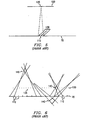
- FIGUREs 2-4 on the reconstruction 120 of the image of the SLM is formed at the same apparent distance and position relative to the elemental hologram 110 as it appeared to the elemental hologram 110 at the time of recording.
- FIGURE 6 shows lines drawn from the boundaries between neighboring elemental holograms 110 on a holographic recording material 70 through the boundaries between neighboring reconstructed pixels 135 of the reconstructed image 120 of a SLM.
- the areas bounded between the lines drawn from the boundaries of at least two elemental holograms represent independently addressable volume elements, or voxels 140.
- a voxel 140 is a component unit which represents an arbitrary three-dimensional object or scene. Assuming that the elemental holograms 110 are larger than the SLM pixels, as shown in FIGURE 6 , the sizes of the voxels 140 increase with increasing distance from the surface of a reconstructed image of a SLM 120.
- the reproduced image will be poor or indiscernible. If the three-dimensional image of an object or scene extends over a wide range of depth, a variation in the sizes of the voxels will also be very undesirable because such a variation would lead to poor image quality.
- US 5,138,471 discloses a method for making holographic images by recording an array of pixels which together form a two or three dimensional composite image.
- EP 1 059 574 discloses a device for forming a hologram for reproducing a three-dimensional image.
- a controller calculates a three-dimensional interference pattern for generating reproduction light associated with a desired three-dimensional image when a recording medium is illuminated with reference light for reproduction, divides the three-dimensional interference pattern into partial interference patterns and calculates reference light and information light for recording for each of the partial interference patterns.
- a final hologram is formed by illuminating the recording mediumwith reference light and information light for recording using a head while changing the relative positional relationship between the recording medium and the head by moving the head with a voice coil motor while transporting the recording medium.
- hologram printers of the prior art have limitations that make them impractical for commercial purposes.
- these prior art printers suffer from: lack of ability to print full-color holographic stereograms; lack of ability to simultaneously expose multiple elemental holograms; lack of flexibility to quickly and easily adjust a hologram printer to print at different elemental hologram sizes; lack of flexibility to easily change the angle of a reference beam to a holographic recording material; lack of ability to control the resolution of a hologram; and lack of ability to create computer generated images which display animation or different images with a change of viewing position.
- the present invention overcomes many of the above noted limitations and problems of prior art hologram printers and methods used to print holographic stereograms with the following structures and methods.
- the present invention is an apparatus and method for printing one-step, full-color, full parallax holographic stereograms utilizing a reference beam-steering system that allows a reference beam to expose a holographic recording material from different angles. More particularly, a coherent beam is split into object and reference beams. The object beam passes through an object beam unit in which a rendered image is displayed, while the reference beam passes through the reference beam-steering system. The object and reference beams interfere with each other at an elemental hologram on a holographic recording material.
- a computer controls the exposure time and the movement of the recording material and may also render the images displayed in the object beam unit. In addition, the computer may also store the images before they are displayed in the object beam unit.
- an apparatus for printing one-step, multi-wavelength holographic stereograms comprising: a first light source configured to produce a first coherent beam; a beam splitter configured to split the first coherent beam into a first object beam and a first reference beam; a material holder configured to hold a holographic recording material having elemental holograms; an object beam unit including at least one spatial light modulator, wherein the spatial light modulator is configured for displaying a rendered image and for conditioning the first object beam with the rendered image to interfere with the first reference beam at a chosen elemental hologram; a second light source configured to produce a second object beam and a second reference beam, wherein the second object beam has a wavelength different from a wavelength of the first object beam, and is directed at the spatial light modulator; a third light source configured to produce a third object beam and a third reference beam, wherein the third object beam has a wavelength different from the wavelengths of the first and second object beams, and is directed at the spatial light
- a method of printing a one-step, multi-wavelength holographic stereogram with elemental holograms comprising the steps of: selecting an elemental hologram; splitting a first coherent light beam into a first object beam and a first reference beam; splitting a second coherent light beam into a second object beam and a second reference beam, wherein the second coherent light beam has a wavelength different from a wavelength of the first coherent light beam; splitting a third coherent light beam into a third object beam and a third reference beam, wherein the third coherent light beam has a wavelength different from the wavelengths of the first and second coherent light beams; rendering an image; conditioning each of the object beams with the rendered image displayed on at least one spatial light modulator; selectively steering the first, second, and third reference beams at the selected elemental hologram; directing the second object beam at the spatial light modulator; directing the third object beam at the spatial light modulator; and interfering each of the conditioned object beams with a corresponding reference beam
- the present invention may also utilize a voxel-control lens placed in the path of the object beam and in close proximity to the holographic recording material to control the resolution of a holographic stereogram.
- the present invention may also utilize interchangeable band-limited diffusers and reference-beam masking plates.
- the present invention incorporates viewing zone techniques to the rendering process for one-step, holographic stereograms to produce animated, one-step holographic stereograms.
- Alternative arrangements include a HOE or other appropriate optics which replace the combination of a lens and a band-limited diffuser.
- a HOE may also replace a lens or a combination of lenses.
- SLMs may include, but are not limited to LCD panels, digital micro-mirror arrays, film, or transparencies.
- computer storage devices may include, but are not limited to hard disks, static or dynamic RAM, flash memory, DVD drives, or tape drives.
- motors may include, but are not limited to DC servo motors, stepper motors, or actuators.
- the present invention provides a system and method for printing one-step, full-color, full-parallax holographic stereograms. Some presently illustrated embodiments are depicted in FIGUREs 7-31 .
- FIGURE 7 One embodiment of the present invention for a printer is illustrated in FIGURE 7 .
- a computer 230 and controllers 305 and 455 are isolated from vibrations by, for example, being supported on vibration isolation table 80.
- the table 80 may be composed of steel with a honeycomb interior.
- the legs of the table 80 may be air pistons which can absorb vibrations. Other types of vibration isolation may also be acceptable.
- the computer 230 and controllers 305 and 455 may be supported on table 80.
- the computer 230 may have multiple ports and serial or parallel cables through which the computer 230 can control devices, like motor controllers, or through which the computer 230 can send output, such as images.
- computer 230 may have computational power and speed sufficient for three-dimensional computer graphics.
- computer 230 may include one or more central processing unit and may include one or more storage devices, for example, hard disks, a redundant array of independent disks, FLASH memory, or static or dynamic RAM, in which rendered images are stored. If more than one central processing unit is used, they may operate independently or in parallel. If more than one storage device is used, they may also operate independently or in parallel.
- lasers 200 are not supported by table 80. The lasers 200 may be lasers of three different colors.
- one laser 200 may be a krypton ion or a HeNe laser to produce a red beam of light
- another laser 200 may be an argon ion or a YAG laser to produce a green beam of light
- a third laser 200 may be an argon ion or a HeCd laser to produce a blue beam of light.
- lasers 200 may be solid state diodes or other types of lasers.
- the beams of light from the lasers 200 may go through open air.
- the beams of light from the lasers 200 may go through pipes so that instabilities due to air currents will be reduced.
- the beams may be transmitted through polarization-preserving optical fibers.
- the coherent light beams 5 produced by the lasers 200 are directed at variable beam splitters 205.
- Variable beam splitters are half-mirrors that split a beam by reflecting part of the beam and transmitting most of the rest of the beam. If fiber optics are used to transmit beams, then fiber optic beam splitters that work by contacting two parallel fibers together and letting the light from the fibers couple may be used.
- the coherent light beam 5 from each of the lasers 200 is split into two beams, an object beam 20 and a reference beam 25. In some embodiments, each object beam 20 and each reference beam 25 may be directed through half-wave plates 30 and polarizers 35.
- each object beam may be reflected off one or more mirror 40.
- the mirrors 40 used in the present invention may be, for example, first surface or front surface mirrors.
- Each object beam 20 may be directed through a low pass spatial filter 220 to remove unwanted noise.
- a low pass spatial filter 220 may include a microscope objective lens and a pinhole.
- Each object beam 20 may then pass through a beam shutter 225.
- the beam shutters 225 may be high-speed, mechanical iris shutters, for example, those used in made the photography industry.
- the beam shutters 225 may be electro-optical systems such as liquid crystal cells or acousto-optical modulator crystals.
- the SLM 90 in the object beam unit, generally 700 can function as a shutter for all three object beams.
- the shutters 225 are controlled by the computer 230.
- the object beams 20 may be then directed through an object beam unit 700.
- the object beams 20 may be directed such that the object beams 20 converge at the plane of a SLM 90.
- SLM 90 may include, but is not limited to, a transmissive LCD panel, a reflective LCD panel, an optically addressed LCD panel, a digital micro-mirror array, film, a projection or a transparency.
- the SLM 90 may receive image input by a video cable from the computer 230.
- multiple SLMs may receive images generated in parallel by multiple central processing units.
- multiple SLMs may receive images from the storage device or devices of computer 230.
- the object beam 20 After passing through the SLM 90, the object beam 20 may pass through a HOE 115, or another system, like those illustrated in FIGUREs 2-4 , that is designed to converge the object beam and evenly expose an area the size of an elemental hologram.
- the HOE 115 may be a transmission-type hologram that can converge three different monochromatic object beams at slightly different angles onto the elemental holograms to be exposed without allowing zeroth-ordered light from any of the object beams to intersect the elemental holograms to be exposed.
- the object beam 20 may then be transmitted through a voxel control lens 500 and may then expose an elemental hologram 110 on a holographic recording material 70 in a material holder 300.
- the holographic recording material 70 may be, but is not limited to, a pan-chromatic photopolymer, a pan-chromatic or monochromatic silver halide photographic emulsion dichromated gelatin, or other suitable photopolymers.
- the holographic recording material 70 may be held securely by a material holder 300 that may be able to translate the holographic recording material in two directions.
- the movement of the material holder 300 may be controlled by film holder motor controller 305 which may be controlled by computer 230.
- each of the reference beams 25 passes through a variable attenuator 210 which allows the intensity of each reference beam 25 to be independently adjusted.
- the reference beams may be reflected off of a mirror 40 before passing through dichroic combiners 215 or other suitable optical combiners.
- a dichroic combiner is a wavelength selective mirror which reflects some wavelengths, but is transparent to other wavelengths.
- the dichroic combiners 215 in FIGURE 7 combine the three reference beams 25 into one beam which may the pass through a beam shutter 225 before passing through a low pass spatial filter 220.
- the reference beam 25 then passes through a reference beam-steering system 400 which controls the angle which the reference beam 25 intersects with the holographic recording material 70.
- a beam-steering mirror system of the reference beam-steering system is controlled by a mirror system motor controller 455 that is controlled by computer 230.
- the present invention allows separate elemental holograms to be printed in different colors. For instance, by placing a beam shutter in the path of each object beam and reference beam and then selectively closing the beam shutters, one elemental hologram may be exposed to only red object and reference beams, another may be exposed to only green object and reference beams, and another may be exposed to only blue object and reference beams.
- FIGURE 8 An embodiment of the present invention in which multiple elemental holograms are simultaneously exposed is depicted in FIGURE 8 .
- the beams from lasers 200 are split by variable beam splitters 205 and then after being reflected by mirrors 40 are split again by additional variable beam splitters 205, thereby forming two or more object beams 20 and two or more reference beams 25 from each laser 200.
- the beams from laser 200 may be split even more times to form more object beams 20 and more reference beams 25.
- Each object beam 20 passes through a low pass filter 220 and a beam shutter 225.
- Each set of three object beams 20 may be reflected by mirrors 40 and pass through a SLM 90, a HOE 115, and a voxel control lens 500 to expose an elemental hologram 110 on a holographic recording material 70 held by a material holder 300.
- the movement of the material holder 300 is controlled by film holder motor controllers that are controlled by computer 230.
- Each set of three reference beams 25 passes through variable attenuators 210 and are combined into a beam by a dichroic combiner 215 or other suitable optical combiners.
- Each of the resulting two reference beams 25 passes through a beam shutter 225 and a low pass spatial filter 220.
- Each reference beam 25 then passes through a beam-steering system 400 before hitting an elemental hologram 110.
- multiple elemental hologram may be simultaneously printed.
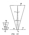
- FIGUREs 9 and 10 An embodiment of the present invention in which the variation in voxel size is controlled is illustrated by FIGUREs 9 and 10 . As shown in FIGUREs 9 and 10 , this control is accomplished by placing a voxel-control lens 500 in the path of an object beam 20 between SLM 90 and holographic recording material 70. The voxel-control lens 500 may be placed in close proximity to holographic recording material 70.
- the voxel-control lens 500 may be capable of making an SLM or a projected image of a SLM seen from the viewpoint of an elemental hologram 110 appear at a greater apparent distance relative to the holographic recording material 70 during recording, so that a sample image point 100 on the SLM 90 surface is reconstructed at a greater distance away from the holographic recording material 70.
- FIGURE 10(a) illustrates how an image 505 of a SLM may appear to an elemental hologram 110 in a printer without a voxel-control lens.
- FIGURE 10(b) illustrates how an image 505 of a SLM may appear to an elemental hologram in a printer with a voxel-control lens 500.
- the voxel control lens magnifies the image 505 of a SLM, such that the angle ⁇ subtended by the image does not change but the angle ⁇ subtended by an elemental hologram decreases to ⁇ when a voxel control lens is used.
- the distance between the image 505 of a SLM and the holographic recording material 70 may be varied by varying the focal length of the voxel-control lens 500 or its position between the holographic recording surface 70 and the converging lens 55 or other optical systems, including simple diffuser or HOEs, as shown in Figures 1-3 , used in the prior art to converge light onto the holographic recording material 70.
- the voxel control lens 500 may be part of the object beam unit 700.
- voxel sizes it is possible to make the voxel sizes fairly constant over a wide range of distances from a holographic recording material 70. This is accomplished by choosing a voxel-control lens 500 with a focal length equal to the distance between the voxel-control lens 500 and the actual location of the SLM or the location of a projected image of the SLM as seen by an elemental hologram in a printer without a voxel-control lens. Such a voxel-control lens 500 and geometrical layout will effectively reconstruct the SLM 120 at an infinite distance relative to holographic recording material 70.
- the voxel 140 boundary lines for such an embodiment will no longer intersect close to the holographic recording material 70 as depicted in FIGURE 6 , but instead become approximately parallel lines which extend out to a great distance without intersecting as shown in Figure 11 .
- a voxel-control lens 500 may depend on the desired results, typically it is desirable for the voxel-control lens 500 to be achromatic and have an f-number of around 3.0 or lower.
- the voxel-control lens may be achromatic and have an f-number of 2.4.
- the voxel-control lens may have lower f-numbers, such as 0.5. Lower f-numbers are desirable because they allow for a wider angle of view.
- the voxel-control lens may be monochromatic.
- FIG 12 depicts yet another embodiment of the present invention.
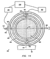
- a reference beam-steering system generally 400, may use a beam-steering mirror system 450 to direct a reference beam 25, through a first beam-steering lens 410 and a second beam-steering lens 405 to an elemental hologram 110 on a holographic recording material 70 which, if desired, may be inclined with respect to the normal to the center axis 420.
- the beam-steering mirror system may be embodied in various ways.
- a deflection mirror 460 is fixedly mounted to a first rotatable mount 465, such that when the first rotatable mount 465 rotates, the deflection mirror 460 rotates about a first axis 451 which passes through center point 461 of the deflection mirror 460.
- a motor for the first rotatable mount 470 which is controlled by a motor controller 455, rotates the first rotatable mount 465.
- the motor for the first rotatable mount 470 is fixedly attached to a support 475.
- First rotatable mount 465 is rotatably mounted to a support 475 with bearings or bushings to allow the first rotatable mount 465 to rotate about the first axis 451.
- Support 475 is fixedly mounted by an attaching device on a second rotatable mount 480 such that when the second rotatable mount 480 rotates, the deflection mirror 460 rotates about a second axis 452 which passes through the center point 461 of the deflection mirror 460 and which is orthogonal to the first axis 451.
- the motor for the second rotatable mount may be fixedly attached to a vibration isolation table 80.
- the motors for the first and second rotatable mounts, 470 and 485, may be, but are not limited to, stepper motors or DC servo motors.
- the same or a separate motor controller 455 controlled by computer 230 may control the motors for the first and second rotatable mounts 470 and 480.
- a deflection mirror 460 is fixedly mounted to a first axle 490 such that the deflection mirror 460 rotates about a first axis 451 which passes through the center point 461 of the deflection mirror 460.
- First axle 490 is rotated by a motor 491 for the first axle which is controlled by a motor controller 455.
- the motor 491 for the first axle is fixedly attached to a first gimbal mount 494.
- First axle 490 is rotatably mounted by bearing or bushing to the first gimbal mount 494.
- the first gimbal mount 494 is fixedly mounted by an attaching device to a second axle 492 at the opposite ends of a diameter of the first gimbal mount 494 that coincides with a second axis 452.
- Second axle 492 is rotated by a motor 493 for the second axle and is controlled by a motor controller 455.
- the deflection mirror 460 rotates about the second axis 452 which passes through the center point 461 of the deflection mirror 460 and which is orthogonal to the first axis 451.
- Second axle 492 is rotatably mounted by bearing or bushing to a second gimbal mount 496.
- the motors 491 and 493, for the first and second axles, 491 and 493 may be, but are not limited to, stepper motors or DC servo motors.
- the same or separate motor controllers 455, controlled by a computer 230, may control the motors for the first and second axles, 491 and 493.
- the center axis 420 of the beam-steering lenses 405, 410 intersects the first axis 451 and the second axis 452 and passes through the center of an elemental hologram.
- a reference beam 25 may be directed at the center point 461 of the deflection mirror 460.
- a computer 230 controls the mirror system motor controller or controllers 455 of the beam-steering mirror system 450, such that a reference beam 25 reflected off the deflection mirror 460 hits an elemental hologram 110 on a holographic recording material 70 at a desired angle.
- the deflection mirror 460 may be placed at a distance of one focal length 411 of the first beam-steering lens away from a first beam-steering lens 410.
- the first beam-steering lens 410 may be placed at a distance of the sum of the focal length 411 of the first beam-steering lens and the focal length 406 of the second beam-steering lens away from the second beam-steering lens 405.
- the second beam-steering lens 405 may be placed at a distance of one focal length 406 of the second beam-steering lens, away from the holographic recording material 70.
- the beam-steering system 400 used in the present invention allows the reference beam 25 to be steered to intersect with elemental hologram 110 at different angles.
- the beam-steering system 400 may include a reference-beam converging lens 415 which may be achromatic or monochromatic. After a reference beam 25 passes through the reference-beam converging lens 415, the reference beam 25 is reflected by a beam-steering mirror system 450 before passing through beam-steering lenses 410 and 405. The first and second beam-steering lenses 410, 405 are placed such that the reference beam 25 that passes through the converging lens and the first beam-steering lens 410 converges in the focal plane 425 of the second beam-steering lens 405.
- center point 461 shown in Figures 15 and 16 of a deflection mirror 460 are shown in Figures 15 and 16 is located at a distance of one focal length 411 of the first beam-steering lens from the first beam-steering lens 410.
- the elemental hologram 110 to be exposed is located at a distance of one focal length of the second beam-steering lens 406 away from the second beam-steering lens 305.
- the beam- steering system 400 may include a beam-steering aperture 430 which eliminates the need to have a reference beam masking plate.
- a reference beam 25 passes through a beam-steering aperture 430 that has the aperture of the area of the elemental hologram 110 to be exposed. If the reference beam passes through lenses that magnify or minify it, then the beam-steering aperture 430 should be sized such that the cross-section of the reference beam that intersects the elemental hologram to be exposed has the same size and shape of the elemental hologram.
- the reference beam 25 then passes through two aperture relay lenses 435, is reflected off of a deflection mirror 460 (shown in Figures 15 and 16 ) of the beam-steering mirror system 450, passes through the first beam-steering lens 410, passes through the second beam-steering lens 405, and then intersects the elemental hologram 110 to be exposed.
- the beam-steering aperture 430 is placed at a distance of one focal length 436 of the aperture relay lenses from one aperture relay lens 435.
- the aperture relay lenses 435 are located two focal lengths 436 of the aperture relay lens away from each other.
- the center point 461 (shown in Figures 15 and 16 ) of the deflection mirror 460 (shown in Figures 15 and 16 ) is located at a distance of one focal length 436 of the aperture relay lens away from the second aperture lens 435 that the reference beam passes through.
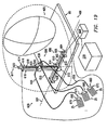
- FIG. 17 , 18 , and 21 Another embodiment of a reference beam-steering system 400 is illustrated by Figures 17 , 18 , and 21 .
- an optical coupler lens 670 channels a reference beam 25 that has just passed through a beam shutter to the fiber optic end 660 of a fiber optic cable 650.
- the fiber optic cable 650 delivers the reference beam 25 to a fiber optic tip 655 which is placed in the focal plane 425 of a second beam-steering lens 405.
- the reference beam 25 passes through a beam-steering lens 405 to an elemental hologram 110.
- the beam-steering lens 405 is located at a distance of one focal length 406 of the second beam-steering lens from the elemental hologram 110 being exposed.
- the fiber optic tip 655 is translated by a translation system, generally 600.
- FIG 19 illustrates another embodiment of the reference beam-steering system 400.
- three reference beams 25 which may each be a different color are channeled by three optical coupler lenses 670 toward three fiber optic ends 660 of three fiber optic cables 650.
- the fiber optic cables 650 deliver the reference beams 25 to fiber optic tips 655 to direct the reference beams 25 into optical combiner unit 640.
- Optical combiner unit 640 may have two dichroic combiners 215, which may combine the three reference beams 25 into a single reference beam 25, other suitable optical combiners.
- the optical combiner unit 640 is placed in the focal plane 425 (shown in Figure 17 ) of a beam-steering lens 405.
- the single reference beam 25 from the optical combiner unit 640 passes through the beam-steering lens 405 to an elemental hologram 110.
- the beam-steering lens 405 is located at a distance of one focal length 406 of the beam-steering lens from the elemental hologram 110 being exposed.
- the optical combiner unit 640 is fixedly mounted to a platform 630 which is fixedly mounted to a second movable support 622.
- three reference beams 25 are transmitted by fiber optic cables 650 to a optical combiner unit 640.
- the single reference beam 25 that is output from the optical combiner unit 640 is channeled by an optical coupler lens 670 into a single fiber optic cable 650 which is attached to and carried by an attaching device to a translation system 600.
- the fiber optic tip 655 of the single fiber optic cable 650 is located in a focal plane 425 of a beam-steering lens 405.
- the three reference beams 25 are transmitted by fiber optic cables 650 to a optical combiner unit 640.
- the single reference beam 25 that is output from the optical combiner unit 640 passes through a beam shutter 225 before it is channeled by an optical coupler lens 670 into a single fiber optic cable 650 which is fixedly attached to a translation system 600.
- the fiber optic tip 655 of the fiber optic cable 650 is located in a focal plane 425 of a beam-steering lens 405.
- the translation system 600 is able to translate in two orthogonal directions.
- the translation system includes a x-translation stage and y-translation stage.
- a x-translation stage 680 includes a first lead screw 602 which is rotatably mounted by bushing, bearing, or other rotatable means to first end plates 608, and which may be rotated about the axis 601 of the first lead screw by a motor 604 for the first lead screw which is fixedly mounted to one of the first end plates 608.
- Two first guide bars 610 are fixedly mounted to the first end plates 608 such that the first guide bars 610 lie parallel to the axis of the first lead screw 601.
- the two first guide bars 610 pass through two holes in a first movable support 612.
- the first lead screw 602 is threaded through a hole in the first movable support 612.
- a y-translation stage 690 includes a second lead screw 618 which is rotatably mounted by bushing, bearing, or other rotatable means to second end plates 614, and which may be rotated about the axis 617 of the second lead screw 618 by a motor 620 for the second lead screw which is mounted to one of the second end plates 614.
- the other of the second end plates 614 is mounted to the first movable support 612 such that the axis 617 of the second lead screw is orthogonal to the axis 601 of the first lead screw.
- Two second guide bars 616 are fixedly mounted to the second end plates 614 such that the second guide bars 616 lie parallel to the axis 617 of the second lead screw.
- the two second guide bars 616 pass through two holes in a second movable support 622.
- the second lead screw 618 is threaded through a hole in the second movable support 622.
- the motors 604 and 620, for the first and second lead screws which may be, but are not limited to stepper, DC servo or linear motors, may be controlled by a motor controller 606 for the motors for the lead screws which may be controlled by computer 230.
- the types, focal lengths, and number of beam-steering lenses may be varied, for some embodiments, it may be desirable for the beam-steering lenses to be achromatic and have f-numbers of around 3.0 or less. In other embodiments, it may be desirable for the beam-steering lenses to be achromatic, confocal, f- ⁇ lenses, which are also known as flat-field laser-scan lenses. In some embodiments, it may also be desirable to have lenses of lower f-number to allow for a wider range of reference beams. In one particular embodiment, it may be desirable to have the beam-steering lenses be achromatic and have f-numbers of around 1.0. In addition, the beam-steering lenses may be monochromatic in other embodiments.
- the beam-steering system used in the present invention may be utilized to create holographic stereograms that display a particular image when illuminated by an illumination source from one angle, but display another image when illuminated by an illumination source from another angle. For instance, after exposing an elemental hologram with an object beam conditioned with a particular image on an SLM and a reference beam at a particular angle, the elemental hologram may then be exposed to an object beam conditioned with another image on the SLM and a reference beam at another angle.
- a set of elemental holograms on a holographic recording material may be exposed by a reference beam at a particular angle, while another set of elemental holograms may be exposed by a reference beam at another angle.
- a printer of this invention can create a holographic stereogram that displays a different image depending on the angle of the illumination source.
- the same printer with a beam-steering system may be used to create multiple holographic stereograms, each with a different reference angle, such that the images of each will only appear when illuminated by an illumination source at the correct angle. If such multiple holographic stereograms are mounted on top of each other, then different images may be displayed by simply changing the angle at which the illumination source intersects the holographic recording materials.
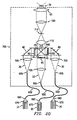
- FIG. 20 Another embodiment of the present invention, illustrated by Figure 20 , utilizes multiple SLMs 90 to produce full-color holographic stereograms.
- two dichroic combiners 215 in an "x" configuration, or other suitable optical combiners may be used in combination with three object beams 20, one object beam being red light, the other green light, and the other blue light.
- the three object beams 20 may be directed through three separate gray-scale SLMs 90.
- the SLMs are LCD panels of high resolution such as 1,280 x 1,024 pixels where the total size of the LCD panel is approximately 10cm x 10cm. However, smaller LCD panels may be used. For instance, LCD panels with the same or fewer number of pixels but that are around 2cm x 2cm in size or smaller may be used.
- object beams 20 after passing through beam shutters 225, object beams 20 are directed through optical coupler lenses 670 to converge at fiber optic ends 660.
- the object beam 20 are then transmitted by fiber optic cables 650 to the fiber optic tips 655 which are placed in the focal planes of singlet lenses 705.
- the object beams 20 may pass through the singlet lenses 705, if necessary, reflect off mirrors 40, and pass through SLMs 90 and band-limited diffusers 45, which may be color specific.
- the singlet lenses 705 expand and collimate the object beams 20 such that the object beams 20 may more evenly illuminate the SLMs 90.
- the object beams 20 are then directed through a optical combiner unit 640 that may use two dichroic combiners 215 in an "x" configuration, or other suitable optical combiners, to combine the three object beams 20 into a single beam.
- the single object beam 20 may then pass through a first projection lens 715 and a Fourier transform filter 710 that may remove undesired effects such as, but not limited to, high frequency image components such as pixel or grid artifacts that resulted from an SLM display with pixels.
- the object beam 20 may then pass through a second projection lens 720 and then a converging lens 55.
- the first projection lens 715 is located such that images of the SLMs all lie in the focal plane of the first projection lens.
- the Fourier transform filter 710 is located in the focal planes of both the first projection lens and the second projection lens.
- the converging lens 55 is located such that its focal plane intersects the holographic recording material 70 at the elemental hologram 110 to be exposed.
- the first and second projection lenses 715 and 720 and the Fourier transform filter 710 are not used.
- a voxel control lens 500 may be included in the object beam unit 700 and lie in close proximity to the holographic recording material 70.
- a material holder may be used to translate holographic recording material 70.
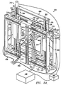
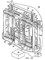
- a material holder 300 may include a frame 324 attached to a x-translation stage 680 that is attached to a y-translation stage 690.
- the y-translation stage 680 may have first holder end plates 302 to which first holder guide rods 306 are fixedly attached.
- a first holder lead screw 308 and a first holder driven lead screw 309 are rotatably attached by bushing or bearing or other suitable means to the first holder end plates 302.
- the first holder lead screw 308 and the first holder guide rods 306 are parallel to the axis of the first holder driven lead screw 307.
- the first holder driven lead screw 309 may be rotated by a motor 310 for the first holder driven lead screw, which is controlled by holder motor controller 305, which is controlled by computer 230.
- the motor 310 may also drive both lead screws 308 and 309 with a timing belt or other linkage.
- two motors 310 each coupled to a lead screw, may drive the lead screws.
- the first holder driven lead screw 309 passes through a threaded hold in the a first holder movable support 312.
- the two first holder guide rods 306 in close proximity to the first holder driven lead screw 309 pass through holes in the same first holder movable support 312.
- the first holder lead screw 308 passes through a threaded hole in another first holder movable support 312, and the two first holder guide rods 306 in close proximity to the first holder lead screw 308 pass through holes in the same first holder movable support 312.
- the x-translation stage 680 may have a second holder lead screw 318 and a first holder driven lead screw 319 rotatably attached by bushing or bearing or other suitable means to second holder end plates 314.
- the axis of the second holder driven lead screw 317 is orthogonal to the axis of the first holder driven lead screw 307.
- the second holder lead screw 318 and the second holder guide rods 316 are parallel to the axis of the second holder driven lead screw 317.
- the second holder driven lead screw 319 may be rotated by a motor 320, for the second holder driven lead screw which is controlled by holder motor controller 305, which is controlled by computer 230.
- the second holder driven lead screw 319 passes through a threaded hole in the a second holder movable support 322.
- the two second holder guide rods 316 in close proximity to the second holder driven lead screw 319 pass through holes in the same second holder movable support 322.
- the second holder lead screw 318 passes through a threaded hole in another second holder movable support 322, and the two second holder guide rods 316 in close proximity to the second holder lead screw 318 pass through holes in the same second holder movable support 322.
- the x-translation stage 680 may be mounted to the y-translation stage 690.
- the first holder movably supports 312 are fixedly mounted to the second holder end plates 314.
- the second holder movable supports 322 are fixedly attached to a frame 324.
- a second frame 324 may be clamped to a first frame 324 by detachable couplings 325 which may include, but are not limited to, clamps, snaps, screws, and bolts.
- a holographic recording material may be held in between two detachably coupled frames 324.
- the natural adhesive property of a holographic recording material may hold the material on one side of a transparent plate that is secured to frames 324.
- the frames 324 may be composed of stress-relieved aluminum, titanium, composites, or other rigid, strong, and lightweight materials.
- object beam units 700 and reference beam-steering systems 400 may be fixed to bases 326.
- one or more object beam units 700 may be fixedly mounted to unit mounts 328 which are fixedly mounted to second holder movable supports 322 of a x-translation stage 680.
- one or more reference beam-steering systems 400 may be fixedly mounted to other second unit mounts 328 which are fixedly mounted to other holder movable supports 322 of another x-translation stage 680.
- a frame 324 may be fixed to the first movable supports 312 of a y-translation stage 690.
- the holographic recording material 70 clamped between two frames 324 may translate vertically, while the object beam units 700 and reference beam-steering systems 400 translate horizontally.
- two motors 320 which are controlled by holder motor controller 305, drive the second holder driven lead screws 319 of the x-translation stages 680.
- one motor 320 in combination with a timing belt 330 that is linked to a belt mount 332 that is fixedly attached to one of the second holder driven lead screws 319, drives both second holder driven lead screws 319 of the x-translation stages 680.
- the object beam units 700 and reference beam-steering systems 400 are attached to unit mounts 328 which are attached to the second holder movable supports 322 of x-translation stages 680.
- a holographic recording material 70 translates vertically by a y-axis roller system 350 with rollers 342 and 344.
- the holographic recording material 70 may be wrapped around a top roller 342 and a bottom roller 344.
- the top and bottom rollers 342 and 344 are rotatably mounted by bushing, bearing, or other suitable means between roller end plates 340.
- the top roller 342 may be rotated by a motor for the rollers 346, which is controlled by a motor controller 305 which is controlled by a computer 230.
- the motors used in the translation systems of the various embodiments may be, but are not limited to stepper motors.
- the printer may include object beam units and reference beam-steering systems attached to translation systems with x-translation stages that are attached to y-translation stages.
- the holographic recording material may be fixed, while the object beam units and reference beam-steering systems are moved by the translation system to record an array of elemental holograms.
- each layer of holographic recording material 70 may be held in a material holder 300.
- each layer may be sensitive to a particular wavelength of light.
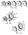
- a matched set of a band-limited diffusers 45 and a reference beam masking plate 65 may be configured to allow for even exposure of an elemental hologram 110 of a particular size or shape and to prevent exposing portions of the holographic recording material 70 that are not part of the elemental hologram 110 intended to be exposed.
- matched sets of band-limited diffusers 45 and reference beam masking plates 65 can be constructed to allow the exposure of elemental holograms 110 of different sizes or shapes. If the sets of band-limited diffusers 45 and reference beam masking plates 65 are constructed such that the band-limited diffusers 45.
- sets can be conveniently switched to easily change the size of the elemental hologram printed.
- a matched set of a band-limited diffuser 45 and a reference beam masking plate 65 can be replaced with another set of a band-limited diffuser 45 and a reference beam masking plate 65 so as to allow printing of a larger, smaller, or differently shaped elemental hologram.
- a band-limited diffuser 45 may be mounted onto a plate 510 housed in a threaded frame 515.
- the plate 510 may be a sheet transparent sheet of glass with an anti-reflective coating.
- the threaded frame 515 may be threaded into positioning device 525 which has a base 526 and a threaded ring 520.
- the positioning device 520 may allow translational adjustment in three orthogonal directions by three adjustable screws 530.
- a reference beam masking plate 65 may be housed in a threaded plate frame 560.
- a threaded plate frame 560 may be threaded into a threaded positioning device 565.
- FIGUREs 7 , 8 , 19 , and 21 Some examples of full-color embodiments of the present invention are depicted in FIGUREs 7 , 8 , 19 , and 21 .
- Another embodiment of the present invention includes a full-color print with three different colored lasers, optical combiners, such as but not limited to dichroic combiners, to combine the three beams from the lasers, a full-color SLM, and achromatic optics to print full-color holographic stereograms.
- Still another embodiment of the present invention includes a full-color printer with three different colored lasers, an object beam unit that combines three object beams using three beam-limited diffusers, three gray-scale SLMs, and an optical combiner, achromatic optics, such as achromatic lenses, to manipulate or condition the full-color beams produced by the printer, and an optical combiner to combine three reference beams into a combined, full-color, reference beam.
- achromatic optics such as achromatic lenses
- Yet another embodiment of the present invention includes a full-color printer with three different colored lasers, an object beam unit with an HOE that combines three different colored object beams into one combined, full-color, object beam and that also evenly distributes the combined object beam over an elemental hologram, an optical combiner to combine three reference beams into a combined, full-color, reference beam, and achromatic optics to manipulate or condition the full-colored beams.
- Another aspect of the present invention involves a method of creating animated, one-step, full-parallax, holographic stereograms.
- One embodiment involves using multiple or sub-divided viewing zones, which typically are not needed to produce static image, full-parallax holographic stereograms, to produce one-step, full-parallax, holographic stereograms that can display animated subjects or different images through different viewing zones.
- Viewing zones are typically planar areas located at a distance from the holographic recording material in which a viewer's eye looking through that plane could see the holographic image produced by an array of elemental holograms.
- a viewing zone may be analogous to a window in front of a hologram.
- viewing zones may also be constructed from a series of points.
- the present invention produces animated, one-stop, full-parallax holographic stereograms by determining the view of an object or scene that an observer would see in each viewing zone.
- the steps for producing a holographic element of an animated holographic stereogram or a holographic stereogram that displays different images in different viewing zones are as follows.
- rendering for multiple elemental holograms may be completed before exposing any of the elemental holograms on a holographic recording material.
- the same method applied for creating holographic stereograms with changing views may be used to create a holographic optical element (HOE).
- HOE holographic optical element
- a HOE holographic optical element
- a HOE can be created by determining a white computer-graphic object with the exact size, shape, and position of a given voxel, and printing a holographic stereogram of such an object.
- the same computer 230 may be programmed to control the motors controlling the beam shutters, the motor controllers for the beam-steering mirror system, the motor controllers for the translation systems, conducts the computer graphics creation and rendering, and controls the display of the SLM. In an alternative embodiment, the same computer may also conduct the computations necessary for animation.
- the computer 230 may be connected to the beam shutters, the motor controllers for the beam-steering mirror system, and the SLM, through cables connected at both ends to serial or parallel communication ports. One end of the cables may be connected to the communication ports of the computer and the other ends of the cables may be connected to the devices controlled by the computer. In other embodiments, multiple computers 230 may be used.
Landscapes
- Physics & Mathematics (AREA)
- General Physics & Mathematics (AREA)
- Optics & Photonics (AREA)
- Holo Graphy (AREA)
Description
- The present invention relates generally to the field of holography. More particularly, it concerns methods and devices for creating and printing variable size and variable resolution holographic stereograms and holographic optical elements using computer rendered images of three-dimensional computer models or using computer processed images.
- A holographic stereogram is a type of hologram synthesized or composed from a set of two-dimensional views of a subject. A holographic stereogram is capable of creating the convincing illusion of a solid three-dimensional subject from closely spaced, discrete-perspective, two-dimensional component views. In addition, if the two-dimensional component views are properly generated, a holographic stereogram can also create the illusion of an animated image. Although holographic stereograms can project such special effects, due to limitations in the methods and techniques for printing holographic stereograms, holographic stereograms have generally been expensive, difficult and time consuming to produce.
- Techniques have been developed for reducing the number of steps involved in producing holographic stereograms to one optical printing step. One-step technology usually involves using computer processed images of objects or computer models of objects to build a hologram from a number of contiguous, small, elemental pieces, known as elemental holograms or hogels. This one-step technology eliminates the need to create a preliminary hologram.
- To produce a full-parallax, holographic stereogram using traditional one-step technology, a three-dimensional computer model of an object or a scene is created. There are numerous computer graphic modeling programs, rendering programs, animation programs, three dimensional digitalization systems, or combinations of the programs or systems that can be used to generate and manipulate a three-dimensional computer model of an object or a scene. Examples of such programs or systems include, but are not limited to, computer-aided-design (CAD) programs, scientific visualization programs, and virtual reality programs.
- In addition, to produce a holographic stereogram using one-step technology requires that the position of the hologram surface and individual elemental holograms relative to an object or a scene be determined. Furthermore, a proper computer graphic camera(s)'s description for an elemental hologram and the size and location of a spatial light modulator (SLM), a device that can display a two-dimensional image, need to be determined.
- Once all the aforementioned initial parameters are determined, a two-dimensional projection on the SLM for each elemental hologram is computed based on the computer graphic model of the object or scene that was created, the positions of the elemental holograms, and the computer graphic camera's description for the elemental holograms. The two-dimensional projection on the SLM for each elemental hologram may be rendered using various computer graphic techniques. The process of creating two-dimensional views from a three-dimensional object and adding qualities such as variations in color and shade to a computer graphic model is often referred to as rendering. There are numerous methods for rendering. One method is ray-tracing, which computes images by accurately simulating sampled light rays in a computer model. Another method is scan-line conversion, which computes images one raster or line at a time. Typically scan-line rendering does not produce as realistic results as ray tracing. However, scan-line rendering is frequently used in animation packages because it is faster. Another method for using computer graphics to render images for one-step, full-parallax holographic stereograms is described in an article by Halle and Kropp. Halle, M. and Kropp, A., "Fast Computer Graphics Rendering for Full Parallax Spatial Displays," Proc. Soc, Photo-Opt. Instrum. Eng. (SPIE), 3011:105-112 (February 10-11, 1997)
- When holographic stereograms are produced by either the multi-step or one-step techniques, the reconstructed images may have geometric image distortions. These geometric image distortions may be very apparent, especially in large, billboard size holographic displays or holographic displays in other geometries, such as an alcove or a partial cylinder.
- One solution that has been incorporated into multi-step techniques to correct for geometric image distortions for multiplex holograms is discussed in an article by Okada. Okada, K., et. al., "A Method of Distortion Compensation of Multiplex Holograms," Optics Communications, vol. 48, no. 3, pp. 167-170 (December 1, 1983)
- The technique discussed in Okada's article to correct distortion is a method to correct geometrical and time distortion of a single or monocular viewpoint of a finished hologram. Because it is a post-processing method that takes place after image acquisition, Okada's technique would be inefficient if adopted to generate animated computer graphics one-step, holographic stereograms. Moreover, Okada's method only produces horizontal-parallax-only transmission type holograms.
- Others have developed techniques for pre-distorting one-step, holographic stereograms to reduce distortion in the final holographic display. One such pre-distortion technique is described in a paper by Halle and others. Halle, M. et al, "The Ultragram: A Generalized Holographic Stereogram," Proc. Soc. Photo-Opt. Instrum. Eng. (SPIE), vol. 1461 Practical Holography V, p. 142 (February 1991)
- Although widely used, typical pre-distortion techniques for one-step methods for producing full-parallax, holographic stereograms are significantly limited by available computer processing speeds and the resolution of images produced by traditional one-step methods. In addition, techniques for pre-distorting one-step, full parallax, holographic stereograms have not been able to produce comprehensible, animated, one step, full parallax, holographic stereograms.
- Apparatus for printing one-step, monochromatic, holographic-stereograms have been developed. Typically, such prior art printers, as depicted in
FIGURE 1 include: a monochromecoherent light source 1,lenses 42,mirrors 40, anoptical system 89, ashutter 10, a mechanism for translatingfilm 69,holographic recording material 70, usually in the form of film, apersonal computer 85 to control the timing for the exposure sequence, and a separate high-speed computer 87 for image calculations. The prior art printer depicted inFIGURE 1 , was discussed in two articles by Yamaguchi. Yamaguchi, M., et al., "Development of a Prototype Full-Parallax Holoprinter," Proc. Soc. Photo-Opt Instrum. Eng. (SPIE) vol. 2406, Practical Holography IX. pp. 50-56 (February 1995); and Yamaguchi, M., et al., "High-Quality Recording of a Full-Parallax Holographic Stereogram with a Digital Diffuser," Optical Letters, vol. 19, no. 2, pp. 135-137 (January 20, 1994) - The prior art printer depicted in
FIGURE 1 is capable of producing monochromatic holographic stereograms, but not full-color holographic stereograms. - A typical prior art hologram printer, like the one depicted in
FIGURE 1 , usually is supported by a vibration isolation table 80. In addition the prior art printer depicted byFIGURE 1 uses a HeNe laser for alight source 1 that produces acoherent light beam 5 that may be collimated. Ashutter 10 is placed at the output oflight source 1. A beam-splitter 15 splits thelight 5 from thelight source 1 into anobject beam 20 and areference beam 25. The polarization of the object andreference beams wave plates 30 and a pair ofpolarizers 35. The half-wave plates 30 andpolarizers 35 also control the ratio of the beams. The prior art printer also uses a number ofmirrors 40. In addition, the prior art printer uses a system of enlarginglenses 42 to distribute theobject beam 20 from thelight source 1 into theoptical system 89 depicted inFIGURE 1 . - The
optical system 89 of the prior art printer ofFIGURE 1 includes a band-limiteddiffuser 45, a liquid crystal display panel (LCD panel) 50, and a converginglens 55. A band-limited diffuse is a diffuser with a deterministic phase pattern designed to diffuse light in a specific pattern or direction. The band-limiteddiffuser 45 depicted inFIGURE 1 is specifically designed for the monochromatic light source being used -- a HeNe laser. TheLCD panel 50 used in the prior art printer ofFIGURE 1 is a gray scale, electrically addressed panel with twisted-nematic liquid crystals. TheLCD panel 50 receives image data calculated by a high-speed computer 87 by an analog video signal. The converginglens 55 shown inFIGURE 1 focuses the images from theLCD panel 50 to theholographic recording material 70. The converginglens 55 generally has a low f-number in order to produce a wide angle of view. Due to the need to correct for spherical aberrations along the optical axis, Yamaguchi utilized a converginglens 55 composed of three lenses to reduce spherical aberration and realize a f-number of around 0.8. - To prevent the exposure of parts of the
holographic recording material 70 that are not part of theelemental hologram 110 meant to be exposed, the prior art printer ofFIGURE 1 , uses, in close proximity to theholographic recording material 70, an objectbeam masking plate 60 with an aperture the size of theelemental hologram 110 to prevent theobject beam 20 from exposing other parts of theholographic recording material 70. - The band-limited
diffuser 45 shown inFIGURE 1 improves the uniformity of the distribution of theobject beam 20 over an elemental hologram on theholographic recording material 70. If the band-limiteddiffuser 45 is designed such that anobject beam 20 is focused only over the area of an elemental hologram, then an objectbeam masking plate 60 is not needed to prevent exposure of areas outside the elemental hologram. However, if used with such a band-limited diffuse, the objectbeam masking plate 60 may have an aperture larger than the size of theelemental hologram 110. Anobject beam 20 and a band-limiteddiffuser 45 that allow even illumination of anelemental hologram 110 by anobject beam 20 need to be matched by a referencebeam masking plate 65 with an aperture the size of theelemental hologram 110. Because the required matching of aobject beam 20, a band-limited diffuse 45, and referencebeam masking plate 65 to the size of a desired elemental hologram, it has been difficult to change the sizes of elemental holograms exposed by a hologram printer. Because of this lack of flexibility, prior art printers cannot easily print holograms having different sizes of elemental holograms, and are restricted to printing holograms with single, fixed-sized elemental holograms. -
FIGUREs 2-4 illustrate alternative prior art examples of optical systems that function in the same way as theoptical system 89 depicted inFIGURE 1 . - In
FIGUREs 2-4 , anobject beam 20 is directed through aSLM 90 that has asample image point 100 on its surface. Theobject beam 20 may be normal to the SLM surface or off-axis from the normal.SLM 90 may also have an array ofpixels 95. LCD panels, cinematography film, and transparencies have been used asSLMs 90. - In
FIGURE 2 , the object beam is directed through asimple diffuser 105, such as a section of ground glass, that scatters light. When asimple diffuser 105 is used, then an objectbeam masking plate 60 must be used to prevent exposing areas of theholographic recording material 70 outside theelemental hologram 110 that are not meant to be exposed. - In
FIGURE 3 , anobject beam 20 is directed through a holographic optical element (HOE) 115. A HOE is a hologram that is specially designed to redirect light emanating from a source in a certain way. For instance, a HOE may be designed to act as a lens to converge light to a single point. As another example, a HOE may be designed to act as a band-limited diffuser that is paired with a lens to converge light over an area rather than a single point. TheHOE 115 depicted inFIGURE 3 is one that is designed to evenly expose an area the size and shape of anelemental hologram 110. When such a HOE is used, an object beam masking plate 60 (shown inFIGURE 2 ) need not be used at all or, if used, may have an aperture larger than the size of theelemental hologram 110 to be exposed. - In
FIGURE 4 , anobject beam 20 is directed through a band-limited diffuser, which may be a band-limited digital diffuser, 45 and a converginglens 55. The band-limiteddiffuser 45 depicted inFIGURE 4 is designed to converge theobject beam 20 over the area ofelemental hologram 110. Thus, an object beam masking plate 60 (shown inFIGURE 2 ) need not be used at all or, if used may have an aperture larger than the size of theelemental hologram 110 to be exposed. - In
FIGUREs 2-4 , thesample image point 100 is an image point of theSLM 90 that is recorded in anelemental hologram 110 on aholographic recording material 70.Reference beam 25 is directed at theelemental hologram 110 such that the interference pattern formed by the interaction of theobject beam 20 and thereference beam 25 may be recorded on theelemental hologram 110 on the holographic 110 on theholographic recording material 70. - To expose a two-dimensional array of elemental holograms, the prior art printer of
FIGURE 1 uses a mechanism for translatingholographic film 69 that includes pulse controlledmotors 71. Typically, theholographic recording material 70 in a prior art printer is photographic film. The film is held between the objectbeam masking plate 60 and the referencebeam masking plate 65. Both maskingplates elemental holograms 110 being exposed. The maskingplates solenoid 72. Pulse controlledmotors 71 translate the film in two directions. - In the prior art system depicted in
FIGURE 1 , the timing of the exposure sequence is controlled by a personal computer. Thus, thesolenoid 72, as well as the pulse controlledmotors 71 and theshutter 10, are controlled by thepersonal computer 85. In contrast, the images for the exposures are calculated off-line by a high-speed computer 87. The image calculations are transferred by an analog video signal to theLCD panel 50. - For a holographic stereogram to be reconstructed, an illumination source must be placed at an appropriate angle. If the illumination source is not placed correctly, a holographic stereogram will not be reconstructed or will appear with distortions, such as magnification distortions. Despite advances in holographic techniques and equipment, the display illumination geometry of a one-step, holographic stereogram remains a problem. The display illumination geometry, i.e., the placement of an illumination source with respect to a holographic stereogram, depends on the cumulative effect of the angles at which a reference beam exposed each of a holographic stereogram's elemental holograms. For example, if the angle at which all of the elemental holograms on a holographic stereogram are exposed to a collimated reference beam is constant, and if the surface of the holographic stereogram is flat, then the holographic stereogram needs a collimated illumination source to illuminate each of the elemental holograms from the appropriate angle if the hologram is to be properly reconstructed without defects such as magnification distortion.
- Furthermore, in practice, it has been common to create reflection holographic stereograms which are meant to be illuminated with a diverging light source such as a point source. However, the prior art has not overcome the difficulty in designing a printer in which the angle of a reference beam is automatically and flexibly changeable to allow reconstruction by a point source and with minimal distortion.
- In addition, it remains difficult to control the resolution or elemental hologram density of a holographic image. The sharpness of a holographic image depends on the image resolution and the extent of any blurring. Blurring can be caused by having a large illumination source, such as that of a long florescent light, illuminate a hologram. In addition, blurring can be caused by the large spectral spread of an illumination source. If an illumination source that is small and monochromatic, such as a laser source expanded through a microscope objective lens (i.e. a small, inexpensive, achromatic, high-power lens), is used, blurring may be minimized, and the sharpness of the holographic image will mainly depend on the image resolution of the hologram.
- The image resolution of a three-dimensional image is defined as the volumetric density of individually distinguishable image points in an image volume. For one-step, holographic stereograms, including full-parallax and horizontal-parallax holograms, this resolution is usually not constant throughout an image volume. For small images of little depth, the variation of image resolution with depth is hardly noticeable. However, for holographic stereograms with significant depth, the variation in image resolution with depth can be very apparent.
- As shown in
FIGURE 5 , if the light from anillumination source 130 that is the same type of light source as that which generated thereference beam 25 that exposed anelemental hologram 110 illuminates theelemental hologram 110 from the appropriate conjugate angle, thereconstruction 125 of thesample image point 100, (shown in -
FIGUREs 2-4 ), on thereconstruction 120 of the image of the SLM is formed at the same apparent distance and position relative to theelemental hologram 110 as it appeared to theelemental hologram 110 at the time of recording. -
FIGURE 6 shows lines drawn from the boundaries between neighboringelemental holograms 110 on aholographic recording material 70 through the boundaries between neighboringreconstructed pixels 135 of thereconstructed image 120 of a SLM. The areas bounded between the lines drawn from the boundaries of at least two elemental holograms represent independently addressable volume elements, orvoxels 140. Avoxel 140 is a component unit which represents an arbitrary three-dimensional object or scene. Assuming that theelemental holograms 110 are larger than the SLM pixels, as shown inFIGURE 6 , the sizes of thevoxels 140 increase with increasing distance from the surface of a reconstructed image of aSLM 120. If the sizes of thevoxels 140 are too coarse relative to the desired detail size of a three-dimensional object or scene, the reproduced image will be poor or indiscernible. If the three-dimensional image of an object or scene extends over a wide range of depth, a variation in the sizes of the voxels will also be very undesirable because such a variation would lead to poor image quality. -
US 5,138,471 discloses a method for making holographic images by recording an array of pixels which together form a two or three dimensional composite image. -
US 4,067,638 discloses multi-color holographic stereograms. -
EP 1 059 574 - Thus, hologram printers of the prior art have limitations that make them impractical for commercial purposes. In particular, these prior art printers suffer from: lack of ability to print full-color holographic stereograms; lack of ability to simultaneously expose multiple elemental holograms; lack of flexibility to quickly and easily adjust a hologram printer to print at different elemental hologram sizes; lack of flexibility to easily change the angle of a reference beam to a holographic recording material; lack of ability to control the resolution of a hologram; and lack of ability to create computer generated images which display animation or different images with a change of viewing position.
- The present invention overcomes many of the above noted limitations and problems of prior art hologram printers and methods used to print holographic stereograms with the following structures and methods.
- The present invention is an apparatus and method for printing one-step, full-color, full parallax holographic stereograms utilizing a reference beam-steering system that allows a reference beam to expose a holographic recording material from different angles. More particularly, a coherent beam is split into object and reference beams. The object beam passes through an object beam unit in which a rendered image is displayed, while the reference beam passes through the reference beam-steering system. The object and reference beams interfere with each other at an elemental hologram on a holographic recording material. A computer controls the exposure time and the movement of the recording material and may also render the images displayed in the object beam unit. In addition, the computer may also store the images before they are displayed in the object beam unit.
- According to an aspect of the present invention, there is provided an apparatus for printing one-step, multi-wavelength holographic stereograms, comprising: a first light source configured to produce a first coherent beam; a beam splitter configured to split the first coherent beam into a first object beam and a first reference beam; a material holder configured to hold a holographic recording material having elemental holograms; an object beam unit including at least one spatial light modulator, wherein the spatial light modulator is configured for displaying a rendered image and for conditioning the first object beam with the rendered image to interfere with the first reference beam at a chosen elemental hologram; a second light source configured to produce a second object beam and a second reference beam, wherein the second object beam has a wavelength different from a wavelength of the first object beam, and is directed at the spatial light modulator; a third light source configured to produce a third object beam and a third reference beam, wherein the third object beam has a wavelength different from the wavelengths of the first and second object beams, and is directed at the spatial light modulator; a reference beam steering system configured to direct the first reference beam to interfere with the first object beam at the chosen elemental hologram to expose the area of the selected elemental hologram, and configured to direct the second reference beam to interfere with the second object beam at the chosen elemental hologram to expose the area of the selected elemental hologram, and configured to direct the third reference beam to interfere with the third object beam at the chosen elemental hologram to expose the area of the selected elemental hologram; and a computer programmed to control at least one of the interference of each of the object beams with a corresponding reference beam of the reference beams at the selected elemental hologram, and the delivery of the rendered image to the object beam unit.
- According to another aspect of the present invention, there is provided a method of printing a one-step, multi-wavelength holographic stereogram with elemental holograms, comprising the steps of: selecting an elemental hologram; splitting a first coherent light beam into a first object beam and a first reference beam; splitting a second coherent light beam into a second object beam and a second reference beam, wherein the second coherent light beam has a wavelength different from a wavelength of the first coherent light beam; splitting a third coherent light beam into a third object beam and a third reference beam, wherein the third coherent light beam has a wavelength different from the wavelengths of the first and second coherent light beams; rendering an image; conditioning each of the object beams with the rendered image displayed on at least one spatial light modulator; selectively steering the first, second, and third reference beams at the selected elemental hologram; directing the second object beam at the spatial light modulator; directing the third object beam at the spatial light modulator; and interfering each of the conditioned object beams with a corresponding reference beam of the reference beams at the selected elemental hologram to expose the area of the selected elemental hologram.
- In addition, the present invention may also utilize a voxel-control lens placed in the path of the object beam and in close proximity to the holographic recording material to control the resolution of a holographic stereogram.
- In addition, the present invention may also utilize interchangeable band-limited diffusers and reference-beam masking plates.
- Furthermore, the present invention incorporates viewing zone techniques to the rendering process for one-step, holographic stereograms to produce animated, one-step holographic stereograms.
- In accordance with long-standing patent law convention, the words "a" and "an" when used in this application, including the claims, denotes "at least one".
- The following drawings form part of the specification and are included to further demonstrate certain aspects of the present invention. The invention may be better understood by reference to one or more of these drawings in combination with the detailed description of specific embodiments presented herein.
-
FIGUREs 1(a) and (b) are schematic, top-view drawings of a prior art hologram printer. -
FIGUREs 2(a) and (b) are simplified, top-view illustrations of a one-step, reflection, elemental hologram recording using an optical system including a simple diffuser. -
FIGURE 3 is a simplified, top-view illustration of a one-step, reflection, elemental hologram recording using an optical system including a holographic optical element. -
FIGURE 4 is a simplified, top-view illustration of a one-step, reflection, elemental hologram recording using an optical system including a band-limited diffuser and a converging lens. -
FIGURE 5 is a simplified, top-view illustration of the reconstruction of an elemental hologram of a holographic stereogram. -
FIGURE 6 is a illustration of the changes in sizes of voxels with distance from a reconstructed image of a SLM. -
FIGURE 7 is a top-view, schematic drawing of one embodiment of the present invention for a one-step, full-color, full-parallax printer for holographic stereograms. -
FIGURE 8 is a top-view, schematic drawing of another embodiment of the present invention for a one-step, full-color, full-parallax printer for holographic stereograms. -
FIGURE 9 is an illustration of a particular embodiment of the present invention to control the variation in sizes of voxels. -
FIGUREs 10(a) and (b) illustrate how the apparent distance of a SLM, as seen by an elemental hologram, may change when a voxel-control lens is utilized. -
FIGURE 11 is an illustration of voxel boundary lines that are approximately parallel to each other. -
FIGURE 12 is a schematic illustration of an embodiment of the reference beam-steering system of the present invention. -
FIGURE 13 is a schematic illustration of another embodiment of the reference beam-steering system of the present invention. -
FIGURE 14 is a schematic illustration of an embodiment of the reference beam-steering system of the present invention that utilizes a beam-steering aperture. -
FIGURE 15 is a orthogonal-view illustration of an embodiment of the beam-steering mirror system of the present invention. -
FIGURE 16 is a front-view illustration of another embodiment of the beam-steering mirror system of the present invention. -
FIGURE 17 is a schematic illustration of an embodiment of the reference beam-steering system of the present invention that utilizes fiber optics and a translation system. -
FIGURE 18 is a simplified, orthogonal-view illustration of an embodiment of the reference beam-steering system of the present invention that utilizes fiber optics and a translation system. -
FIGURE 19 is a simplified, orthogonal-view illustration of an embodiment of a reference beam-steering system of the present invention that utilizes fiber optics, a translation system, and a optical combiner unit. -
FIGURE 20 is a schematic illustration of an object beam unit of the present invention that utilizes the fiber optics. -
FIGURE 21 is a top-view, schematic drawing of one embodiment, which utilizes fiber optics, of the present invention for a one-step, full-color, full-parallax printer for holographic stereograms. -
FIGURE 22 is a simplified, orthogonal-view illustration of an embodiment of a material holder of the present invention. -
FIGURE 23 is a schematic illustration of an embodiment of the present invention with fixed object beam units and fixed reference beam-steering systems. -
FIGURE 24 is a schematic illustration of an embodiment of the present invention with mobile object beam units and mobile reference beam-steering systems. -
FIGURE 25 is a schematic illustration of another embodiment of the present invention with mobile object beam units and mobile reference beam-steering systems. -
FIGURE 26 is a schematic illustration of yet another embodiment of the present invention with mobile object beam units and mobile reference beam-steering systems. -
FIGUREs 27(a), (b), and (c) are orthogonal-view illustrations of removable band-limited diffusers and removable reference beam masking plates. -
Figure 28 is a flow chart illustrating the steps for creating an animated, one-step, full-parallax holographic stereogram. -
FIGURE 29 is an illustration of viewing zones for a holographic stereogram that displays different images when viewed from different viewing zones. -
FIGURE 30 is an illustration of rays projecting from the perimeter of viewing zones. -
FIGURE 31 is an illustration of viewing zone mask volumes. - The following examples are included to demonstrate illustrative embodiments of the present invention. It should be appreciated by those with skill in the art that the techniques disclosed in the following examples represent techniques discovered by the inventors to function well in practice, and thus can be considered to constitute exemplary modes for its practice.
- Alternative arrangements include a HOE or other appropriate optics which replace the combination of a lens and a band-limited diffuser. In addition, a HOE may also replace a lens or a combination of lenses. Furthermore, SLMs may include, but are not limited to LCD panels, digital micro-mirror arrays, film, or transparencies. In addition, computer storage devices may include, but are not limited to hard disks, static or dynamic RAM, flash memory, DVD drives, or tape drives. Moreover, motors may include, but are not limited to DC servo motors, stepper motors, or actuators.
- The present invention provides a system and method for printing one-step, full-color, full-parallax holographic stereograms. Some presently illustrated embodiments are depicted in
FIGUREs 7-31 . - One embodiment of the present invention for a printer is illustrated in
FIGURE 7 . As depicted inFIGURE 7 , most of the parts of the printer, except for acomputer 230 andcontrollers computer 230 andcontrollers computer 230 may have multiple ports and serial or parallel cables through which thecomputer 230 can control devices, like motor controllers, or through which thecomputer 230 can send output, such as images. In addition,computer 230 may have computational power and speed sufficient for three-dimensional computer graphics. Furthermore,computer 230 may include one or more central processing unit and may include one or more storage devices, for example, hard disks, a redundant array of independent disks, FLASH memory, or static or dynamic RAM, in which rendered images are stored. If more than one central processing unit is used, they may operate independently or in parallel. If more than one storage device is used, they may also operate independently or in parallel. In some embodiments,lasers 200 are not supported by table 80. Thelasers 200 may be lasers of three different colors. For example, onelaser 200 may be a krypton ion or a HeNe laser to produce a red beam of light, anotherlaser 200 may be an argon ion or a YAG laser to produce a green beam of light, and athird laser 200 may be an argon ion or a HeCd laser to produce a blue beam of light. Other light wavelengths are also acceptable. In addition,lasers 200 may be solid state diodes or other types of lasers. The beams of light from thelasers 200 may go through open air. In addition, the beams of light from thelasers 200 may go through pipes so that instabilities due to air currents will be reduced. Also, the beams may be transmitted through polarization-preserving optical fibers. - In
FIGURE 7 , thecoherent light beams 5 produced by thelasers 200 are directed atvariable beam splitters 205. Variable beam splitters are half-mirrors that split a beam by reflecting part of the beam and transmitting most of the rest of the beam. If fiber optics are used to transmit beams, then fiber optic beam splitters that work by contacting two parallel fibers together and letting the light from the fibers couple may be used. Thecoherent light beam 5 from each of thelasers 200 is split into two beams, anobject beam 20 and areference beam 25. In some embodiments, eachobject beam 20 and eachreference beam 25 may be directed through half-wave plates 30 andpolarizers 35. In other embodiments, if polarization-retaining fiber optic cables are used to transmit a beam and if the cables are rotatable about their center axes, half-wave plates 30 need not be used. If needed, each object beam may be reflected off one ormore mirror 40. Themirrors 40 used in the present invention may be, for example, first surface or front surface mirrors. Eachobject beam 20 may be directed through a low passspatial filter 220 to remove unwanted noise. A low passspatial filter 220 may include a microscope objective lens and a pinhole. Eachobject beam 20 may then pass through abeam shutter 225. In one embodiment, thebeam shutters 225 may be high-speed, mechanical iris shutters, for example, those used in made the photography industry. In other embodiments, thebeam shutters 225 may be electro-optical systems such as liquid crystal cells or acousto-optical modulator crystals. In another embodiment, instead of usingseparate beam shutters 225, theSLM 90 in the object beam unit, generally 700, can function as a shutter for all three object beams. Theshutters 225 are controlled by thecomputer 230. The object beams 20 may be then directed through anobject beam unit 700. In theobject beam unit 700, the object beams 20 may be directed such that the object beams 20 converge at the plane of aSLM 90.SLM 90 may include, but is not limited to, a transmissive LCD panel, a reflective LCD panel, an optically addressed LCD panel, a digital micro-mirror array, film, a projection or a transparency. TheSLM 90 may receive image input by a video cable from thecomputer 230. In addition, multiple SLMs may receive images generated in parallel by multiple central processing units. Moreover, multiple SLMs may receive images from the storage device or devices ofcomputer 230. After passing through theSLM 90, theobject beam 20 may pass through aHOE 115, or another system, like those illustrated inFIGUREs 2-4 , that is designed to converge the object beam and evenly expose an area the size of an elemental hologram. In one implementation, theHOE 115 may be a transmission-type hologram that can converge three different monochromatic object beams at slightly different angles onto the elemental holograms to be exposed without allowing zeroth-ordered light from any of the object beams to intersect the elemental holograms to be exposed. After passing through theobject beam unit 700, theobject beam 20 may then be transmitted through avoxel control lens 500 and may then expose anelemental hologram 110 on aholographic recording material 70 in amaterial holder 300. Theholographic recording material 70 may be, but is not limited to, a pan-chromatic photopolymer, a pan-chromatic or monochromatic silver halide photographic emulsion dichromated gelatin, or other suitable photopolymers. Theholographic recording material 70 may be held securely by amaterial holder 300 that may be able to translate the holographic recording material in two directions. The movement of thematerial holder 300 may be controlled by filmholder motor controller 305 which may be controlled bycomputer 230. - As further depicted in
FIGURE 7 , after the beams are split into object beams 20 andreference beams 25 by thevariable beam splitters 205, each of the reference beams 25 passes through avariable attenuator 210 which allows the intensity of eachreference beam 25 to be independently adjusted. The reference beams may be reflected off of amirror 40 before passing throughdichroic combiners 215 or other suitable optical combiners. A dichroic combiner is a wavelength selective mirror which reflects some wavelengths, but is transparent to other wavelengths. Thedichroic combiners 215 inFIGURE 7 combine the threereference beams 25 into one beam which may the pass through abeam shutter 225 before passing through a low passspatial filter 220. Thereference beam 25 then passes through a reference beam-steering system 400 which controls the angle which thereference beam 25 intersects with theholographic recording material 70. A beam-steering mirror system of the reference beam-steering system is controlled by a mirrorsystem motor controller 455 that is controlled bycomputer 230. - Furthermore, the present invention allows separate elemental holograms to be printed in different colors. For instance, by placing a beam shutter in the path of each object beam and reference beam and then selectively closing the beam shutters, one elemental hologram may be exposed to only red object and reference beams, another may be exposed to only green object and reference beams, and another may be exposed to only blue object and reference beams.
- An embodiment of the present invention in which multiple elemental holograms are simultaneously exposed is depicted in
FIGURE 8 . The beams fromlasers 200 are split byvariable beam splitters 205 and then after being reflected bymirrors 40 are split again by additionalvariable beam splitters 205, thereby forming two or more object beams 20 and two ormore reference beams 25 from eachlaser 200. In other embodiments, the beams fromlaser 200 may be split even more times to form more object beams 20 and more reference beams 25. Eachobject beam 20 passes through alow pass filter 220 and abeam shutter 225. Each set of threeobject beams 20 may be reflected bymirrors 40 and pass through aSLM 90, aHOE 115, and avoxel control lens 500 to expose anelemental hologram 110 on aholographic recording material 70 held by amaterial holder 300. The movement of thematerial holder 300 is controlled by film holder motor controllers that are controlled bycomputer 230. Each set of threereference beams 25 passes throughvariable attenuators 210 and are combined into a beam by adichroic combiner 215 or other suitable optical combiners. Each of the resulting tworeference beams 25 passes through abeam shutter 225 and a low passspatial filter 220. Eachreference beam 25 then passes through a beam-steering system 400 before hitting anelemental hologram 110. Thus, as depicted inFIGURE 8 , multiple elemental hologram may be simultaneously printed. - An embodiment of the present invention in which the variation in voxel size is controlled is illustrated by
FIGUREs 9 and10 . As shown inFIGUREs 9 and10 , this control is accomplished by placing a voxel-control lens 500 in the path of anobject beam 20 betweenSLM 90 andholographic recording material 70. The voxel-control lens 500 may be placed in close proximity toholographic recording material 70. The voxel-control lens 500 may be capable of making an SLM or a projected image of a SLM seen from the viewpoint of anelemental hologram 110 appear at a greater apparent distance relative to theholographic recording material 70 during recording, so that asample image point 100 on theSLM 90 surface is reconstructed at a greater distance away from theholographic recording material 70.FIGURE 10(a) illustrates how animage 505 of a SLM may appear to anelemental hologram 110 in a printer without a voxel-control lens.FIGURE 10(b) illustrates how animage 505 of a SLM may appear to an elemental hologram in a printer with a voxel-control lens 500. As shown inFIGURE 10 , the voxel control lens magnifies theimage 505 of a SLM, such that the angle α subtended by the image does not change but the angle φ subtended by an elemental hologram decreases to θ when a voxel control lens is used. The distance between theimage 505 of a SLM and theholographic recording material 70 may be varied by varying the focal length of the voxel-control lens 500 or its position between theholographic recording surface 70 and the converginglens 55 or other optical systems, including simple diffuser or HOEs, as shown inFigures 1-3 , used in the prior art to converge light onto theholographic recording material 70. In some embodiments, thevoxel control lens 500 may be part of theobject beam unit 700. - In one particular embodiment of this invention, it is possible to make the voxel sizes fairly constant over a wide range of distances from a
holographic recording material 70. This is accomplished by choosing a voxel-control lens 500 with a focal length equal to the distance between the voxel-control lens 500 and the actual location of the SLM or the location of a projected image of the SLM as seen by an elemental hologram in a printer without a voxel-control lens. Such a voxel-control lens 500 and geometrical layout will effectively reconstruct theSLM 120 at an infinite distance relative toholographic recording material 70. If the size of thepixels 95 on aSLM 90 are small compared to the size of theelemental holograms 110, the voxel 140 boundary lines for such an embodiment will no longer intersect close to theholographic recording material 70 as depicted inFIGURE 6 , but instead become approximately parallel lines which extend out to a great distance without intersecting as shown inFigure 11 . - Although the characteristics of a voxel-
control lens 500 may depend on the desired results, typically it is desirable for the voxel-control lens 500 to be achromatic and have an f-number of around 3.0 or lower. In one particular embodiment, the voxel-control lens may be achromatic and have an f-number of 2.4. In other embodiments, the voxel-control lens may have lower f-numbers, such as 0.5. Lower f-numbers are desirable because they allow for a wider angle of view. In yet other embodiments, the voxel-control lens may be monochromatic. -
Figure 12 depicts yet another embodiment of the present invention. Referring toFigures 12-16 , a reference beam-steering system, generally 400, may use a beam-steering mirror system 450 to direct areference beam 25, through a first beam-steering lens 410 and a second beam-steering lens 405 to anelemental hologram 110 on aholographic recording material 70 which, if desired, may be inclined with respect to the normal to thecenter axis 420. - The beam-steering mirror system, generally 450, may be embodied in various ways. One particular embodiment is depicted in
Figure 15 . InFigure 15 , adeflection mirror 460 is fixedly mounted to a firstrotatable mount 465, such that when the firstrotatable mount 465 rotates, thedeflection mirror 460 rotates about afirst axis 451 which passes throughcenter point 461 of thedeflection mirror 460. A motor for the firstrotatable mount 470, which is controlled by amotor controller 455, rotates the firstrotatable mount 465. The motor for the firstrotatable mount 470 is fixedly attached to asupport 475. Firstrotatable mount 465 is rotatably mounted to asupport 475 with bearings or bushings to allow the firstrotatable mount 465 to rotate about thefirst axis 451.Support 475 is fixedly mounted by an attaching device on a secondrotatable mount 480 such that when the secondrotatable mount 480 rotates, thedeflection mirror 460 rotates about asecond axis 452 which passes through thecenter point 461 of thedeflection mirror 460 and which is orthogonal to thefirst axis 451. A motor for the secondrotatable mount 485, which is controlled by amotor controller 455, rotates the secondrotatable mount 480. The motor for the second rotatable mount may be fixedly attached to a vibration isolation table 80. The motors for the first and second rotatable mounts, 470 and 485, may be, but are not limited to, stepper motors or DC servo motors. The same or aseparate motor controller 455 controlled bycomputer 230 may control the motors for the first and second rotatable mounts 470 and 480. - Another suitable a beam-
steering mirror system 450 is a deflection mirror attached to a gimbal mount. InFigure 16 , adeflection mirror 460 is fixedly mounted to afirst axle 490 such that thedeflection mirror 460 rotates about afirst axis 451 which passes through thecenter point 461 of thedeflection mirror 460.First axle 490 is rotated by amotor 491 for the first axle which is controlled by amotor controller 455. Themotor 491 for the first axle is fixedly attached to afirst gimbal mount 494.First axle 490 is rotatably mounted by bearing or bushing to thefirst gimbal mount 494. Thefirst gimbal mount 494 is fixedly mounted by an attaching device to asecond axle 492 at the opposite ends of a diameter of thefirst gimbal mount 494 that coincides with asecond axis 452.Second axle 492 is rotated by amotor 493 for the second axle and is controlled by amotor controller 455. Thedeflection mirror 460 rotates about thesecond axis 452 which passes through thecenter point 461 of thedeflection mirror 460 and which is orthogonal to thefirst axis 451.Second axle 492 is rotatably mounted by bearing or bushing to asecond gimbal mount 496. Themotors separate motor controllers 455, controlled by acomputer 230, may control the motors for the first and second axles, 491 and 493. - As shown in
Figures 12-16 , thecenter axis 420 of the beam-steering lenses first axis 451 and thesecond axis 452 and passes through the center of an elemental hologram. Areference beam 25 may be directed at thecenter point 461 of thedeflection mirror 460. Acomputer 230 controls the mirror system motor controller orcontrollers 455 of the beam-steering mirror system 450, such that areference beam 25 reflected off thedeflection mirror 460 hits anelemental hologram 110 on aholographic recording material 70 at a desired angle. Thedeflection mirror 460 may be placed at a distance of onefocal length 411 of the first beam-steering lens away from a first beam-steering lens 410. The first beam-steering lens 410 may be placed at a distance of the sum of thefocal length 411 of the first beam-steering lens and thefocal length 406 of the second beam-steering lens away from the second beam-steering lens 405. The second beam-steering lens 405 may be placed at a distance of onefocal length 406 of the second beam-steering lens, away from theholographic recording material 70. The beam-steering system 400 used in the present invention allows thereference beam 25 to be steered to intersect withelemental hologram 110 at different angles. - In another embodiment, depicted in
Figure 13 , the beam-steering system 400 may include a reference-beam converging lens 415 which may be achromatic or monochromatic. After areference beam 25 passes through the reference-beam converging lens 415, thereference beam 25 is reflected by a beam-steering mirror system 450 before passing through beam-steering lenses steering lenses reference beam 25 that passes through the converging lens and the first beam-steering lens 410 converges in thefocal plane 425 of the second beam-steering lens 405. In addition, thecenter point 461 shown inFigures 15 and16 of adeflection mirror 460 are shown inFigures 15 and16 is located at a distance of onefocal length 411 of the first beam-steering lens from the first beam-steering lens 410. Furthermore, theelemental hologram 110 to be exposed is located at a distance of one focal length of the second beam-steering lens 406 away from the second beam-steering lens 305. - In another embodiment, depicted in
Figure 14 , the beam-steering system 400 may include a beam-steering aperture 430 which eliminates the need to have a reference beam masking plate. In an embodiment, areference beam 25 passes through a beam-steering aperture 430 that has the aperture of the area of theelemental hologram 110 to be exposed. If the reference beam passes through lenses that magnify or minify it, then the beam-steering aperture 430 should be sized such that the cross-section of the reference beam that intersects the elemental hologram to be exposed has the same size and shape of the elemental hologram. Thereference beam 25 then passes through twoaperture relay lenses 435, is reflected off of a deflection mirror 460 (shown inFigures 15 and16 ) of the beam-steering mirror system 450, passes through the first beam-steering lens 410, passes through the second beam-steering lens 405, and then intersects theelemental hologram 110 to be exposed. The beam-steering aperture 430 is placed at a distance of onefocal length 436 of the aperture relay lenses from oneaperture relay lens 435. Theaperture relay lenses 435 are located twofocal lengths 436 of the aperture relay lens away from each other. Then the center point 461 (shown inFigures 15 and16 ) of the deflection mirror 460 (shown inFigures 15 and16 ) is located at a distance of onefocal length 436 of the aperture relay lens away from thesecond aperture lens 435 that the reference beam passes through. - Another embodiment of a reference beam-
steering system 400 is illustrated byFigures 17 ,18 , and21 . In this embodiment, anoptical coupler lens 670 channels areference beam 25 that has just passed through a beam shutter to the fiberoptic end 660 of afiber optic cable 650. Thefiber optic cable 650 delivers thereference beam 25 to afiber optic tip 655 which is placed in thefocal plane 425 of a second beam-steering lens 405. Thereference beam 25 passes through a beam-steering lens 405 to anelemental hologram 110. The beam-steering lens 405 is located at a distance of onefocal length 406 of the second beam-steering lens from theelemental hologram 110 being exposed. Thefiber optic tip 655 is translated by a translation system, generally 600. -
Figure 19 illustrates another embodiment of the reference beam-steering system 400. In this embodiment, threereference beams 25 which may each be a different color are channeled by threeoptical coupler lenses 670 toward three fiber optic ends 660 of threefiber optic cables 650. Thefiber optic cables 650 deliver the reference beams 25 to fiberoptic tips 655 to direct the reference beams 25 intooptical combiner unit 640.Optical combiner unit 640 may have twodichroic combiners 215, which may combine the threereference beams 25 into asingle reference beam 25, other suitable optical combiners. Theoptical combiner unit 640 is placed in the focal plane 425 (shown inFigure 17 ) of a beam-steering lens 405. Thesingle reference beam 25 from theoptical combiner unit 640 passes through the beam-steering lens 405 to anelemental hologram 110. The beam-steering lens 405 is located at a distance of onefocal length 406 of the beam-steering lens from theelemental hologram 110 being exposed. Theoptical combiner unit 640 is fixedly mounted to aplatform 630 which is fixedly mounted to a secondmovable support 622. - In another embodiment, three
reference beams 25 are transmitted byfiber optic cables 650 to aoptical combiner unit 640. Thesingle reference beam 25 that is output from theoptical combiner unit 640 is channeled by anoptical coupler lens 670 into a singlefiber optic cable 650 which is attached to and carried by an attaching device to atranslation system 600. Thefiber optic tip 655 of the singlefiber optic cable 650 is located in afocal plane 425 of a beam-steering lens 405. - In still another embodiment, the three
reference beams 25 are transmitted byfiber optic cables 650 to aoptical combiner unit 640. Thesingle reference beam 25 that is output from theoptical combiner unit 640 passes through abeam shutter 225 before it is channeled by anoptical coupler lens 670 into a singlefiber optic cable 650 which is fixedly attached to atranslation system 600. Thefiber optic tip 655 of thefiber optic cable 650 is located in afocal plane 425 of a beam-steering lens 405. - The
translation system 600, as depicted inFigure 18 andFigure 19 , is able to translate in two orthogonal directions. The translation system includes a x-translation stage and y-translation stage. - One illustrative embodiment of a
x-translation stage 680 includes afirst lead screw 602 which is rotatably mounted by bushing, bearing, or other rotatable means tofirst end plates 608, and which may be rotated about theaxis 601 of the first lead screw by amotor 604 for the first lead screw which is fixedly mounted to one of thefirst end plates 608. Two first guide bars 610 are fixedly mounted to thefirst end plates 608 such that the first guide bars 610 lie parallel to the axis of thefirst lead screw 601. The two first guide bars 610 pass through two holes in a firstmovable support 612. Thefirst lead screw 602 is threaded through a hole in the firstmovable support 612. Thus, in this embodiment of thex-translation stage 680, when thefirst lead screw 602 is rotated by themotor 604 for the first lead screw, the firstmovable support 612 will move along theaxis 601 of the first lead screw. - One illustrative embodiment of a y-
translation stage 690 includes asecond lead screw 618 which is rotatably mounted by bushing, bearing, or other rotatable means tosecond end plates 614, and which may be rotated about theaxis 617 of thesecond lead screw 618 by a motor 620 for the second lead screw which is mounted to one of thesecond end plates 614. The other of thesecond end plates 614 is mounted to the firstmovable support 612 such that theaxis 617 of the second lead screw is orthogonal to theaxis 601 of the first lead screw. Two second guide bars 616 are fixedly mounted to thesecond end plates 614 such that the second guide bars 616 lie parallel to theaxis 617 of the second lead screw. The two second guide bars 616 pass through two holes in a secondmovable support 622. Thesecond lead screw 618 is threaded through a hole in the secondmovable support 622. Thus, in this embodiment of the y-translation device 690, when thesecond lead screw 618 is rotated by the motor for the second lead screw 620, the secondmovable support 622 will move along theaxis 617 of the second lead screw. - The
motors 604 and 620, for the first and second lead screws which may be, but are not limited to stepper, DC servo or linear motors, may be controlled by amotor controller 606 for the motors for the lead screws which may be controlled bycomputer 230. - Although the types, focal lengths, and number of beam-steering lenses may be varied, for some embodiments, it may be desirable for the beam-steering lenses to be achromatic and have f-numbers of around 3.0 or less. In other embodiments, it may be desirable for the beam-steering lenses to be achromatic, confocal, f-θ lenses, which are also known as flat-field laser-scan lenses. In some embodiments, it may also be desirable to have lenses of lower f-number to allow for a wider range of reference beams. In one particular embodiment, it may be desirable to have the beam-steering lenses be achromatic and have f-numbers of around 1.0. In addition, the beam-steering lenses may be monochromatic in other embodiments.
- The beam-steering system used in the present invention may be utilized to create holographic stereograms that display a particular image when illuminated by an illumination source from one angle, but display another image when illuminated by an illumination source from another angle. For instance, after exposing an elemental hologram with an object beam conditioned with a particular image on an SLM and a reference beam at a particular angle, the elemental hologram may then be exposed to an object beam conditioned with another image on the SLM and a reference beam at another angle. In addition, a set of elemental holograms on a holographic recording material may be exposed by a reference beam at a particular angle, while another set of elemental holograms may be exposed by a reference beam at another angle. Thus, a printer of this invention can create a holographic stereogram that displays a different image depending on the angle of the illumination source. Furthermore, the same printer with a beam-steering system may be used to create multiple holographic stereograms, each with a different reference angle, such that the images of each will only appear when illuminated by an illumination source at the correct angle. If such multiple holographic stereograms are mounted on top of each other, then different images may be displayed by simply changing the angle at which the illumination source intersects the holographic recording materials.
- Another embodiment of the present invention, illustrated by
Figure 20 , utilizesmultiple SLMs 90 to produce full-color holographic stereograms. InFigure 20 , twodichroic combiners 215 in an "x" configuration, or other suitable optical combiners, may be used in combination with threeobject beams 20, one object beam being red light, the other green light, and the other blue light. The threeobject beams 20 may be directed through three separate gray-scale SLMs 90. In one embodiment of the present invention the SLMs are LCD panels of high resolution such as 1,280 x 1,024 pixels where the total size of the LCD panel is approximately 10cm x 10cm. However, smaller LCD panels may be used. For instance, LCD panels with the same or fewer number of pixels but that are around 2cm x 2cm in size or smaller may be used. - In an embodiment shown in
Figure 20 andFigure 21 , after passing throughbeam shutters 225, object beams 20 are directed throughoptical coupler lenses 670 to converge at fiber optic ends 660. Theobject beam 20 are then transmitted byfiber optic cables 650 to the fiberoptic tips 655 which are placed in the focal planes ofsinglet lenses 705. The object beams 20 may pass through thesinglet lenses 705, if necessary, reflect off mirrors 40, and pass throughSLMs 90 and band-limiteddiffusers 45, which may be color specific. Thesinglet lenses 705 expand and collimate the object beams 20 such that the object beams 20 may more evenly illuminate theSLMs 90. The object beams 20 are then directed through aoptical combiner unit 640 that may use twodichroic combiners 215 in an "x" configuration, or other suitable optical combiners, to combine the threeobject beams 20 into a single beam. Thesingle object beam 20 may then pass through afirst projection lens 715 and aFourier transform filter 710 that may remove undesired effects such as, but not limited to, high frequency image components such as pixel or grid artifacts that resulted from an SLM display with pixels. Theobject beam 20 may then pass through asecond projection lens 720 and then a converginglens 55. Thefirst projection lens 715 is located such that images of the SLMs all lie in the focal plane of the first projection lens. TheFourier transform filter 710 is located in the focal planes of both the first projection lens and the second projection lens. The converginglens 55 is located such that its focal plane intersects theholographic recording material 70 at theelemental hologram 110 to be exposed. In other embodiments of theobject beam unit 700, the first andsecond projection lenses Fourier transform filter 710 are not used. In still other embodiments of theobject beam unit 700, avoxel control lens 500 may be included in theobject beam unit 700 and lie in close proximity to theholographic recording material 70. - In one embodiment of the present invention, a material holder, generally 300, may be used to translate
holographic recording material 70. As depicted inFigures 22-25 , amaterial holder 300 may include aframe 324 attached to ax-translation stage 680 that is attached to a y-translation stage 690. - In one embodiment, the y-
translation stage 680, as depicted inFigures 22-25 , may have firstholder end plates 302 to which firstholder guide rods 306 are fixedly attached. A firstholder lead screw 308 and a first holder drivenlead screw 309 are rotatably attached by bushing or bearing or other suitable means to the firstholder end plates 302. The firstholder lead screw 308 and the firstholder guide rods 306 are parallel to the axis of the first holder drivenlead screw 307. The first holder drivenlead screw 309 may be rotated by amotor 310 for the first holder driven lead screw, which is controlled byholder motor controller 305, which is controlled bycomputer 230. Themotor 310 may also drive bothlead screws motors 310, each coupled to a lead screw, may drive the lead screws. The first holder drivenlead screw 309 passes through a threaded hold in the a first holdermovable support 312. The two firstholder guide rods 306 in close proximity to the first holder drivenlead screw 309 pass through holes in the same first holdermovable support 312. The firstholder lead screw 308 passes through a threaded hole in another first holdermovable support 312, and the two firstholder guide rods 306 in close proximity to the firstholder lead screw 308 pass through holes in the same first holdermovable support 312. - In another embodiment, the
x-translation stage 680, as depicted inFigures 22-26 , may have a secondholder lead screw 318 and a first holder drivenlead screw 319 rotatably attached by bushing or bearing or other suitable means to secondholder end plates 314. The axis of the second holder drivenlead screw 317 is orthogonal to the axis of the first holder drivenlead screw 307. The secondholder lead screw 318 and the secondholder guide rods 316 are parallel to the axis of the second holder drivenlead screw 317. The second holder drivenlead screw 319 may be rotated by amotor 320, for the second holder driven lead screw which is controlled byholder motor controller 305, which is controlled bycomputer 230. The second holder drivenlead screw 319 passes through a threaded hole in the a second holdermovable support 322. The two secondholder guide rods 316 in close proximity to the second holder drivenlead screw 319 pass through holes in the same second holdermovable support 322. The secondholder lead screw 318 passes through a threaded hole in another second holdermovable support 322, and the two secondholder guide rods 316 in close proximity to the secondholder lead screw 318 pass through holes in the same second holdermovable support 322. - As depicted in
FIGUREs 22 and23 , thex-translation stage 680 may be mounted to the y-translation stage 690. In one embodiment, the first holder movably supports 312 are fixedly mounted to the secondholder end plages 314. The second holdermovable supports 322 are fixedly attached to aframe 324. Asecond frame 324 may be clamped to afirst frame 324 bydetachable couplings 325 which may include, but are not limited to, clamps, snaps, screws, and bolts. A holographic recording material may be held in between two detachably coupled frames 324. In an alternative embodiment, the natural adhesive property of a holographic recording material may hold the material on one side of a transparent plate that is secured toframes 324. Theframes 324 may be composed of stress-relieved aluminum, titanium, composites, or other rigid, strong, and lightweight materials. - As illustrated in
FIGURE 23 ,object beam units 700 and reference beam-steeringsystems 400 may be fixed tobases 326. - As illustrated in
FIGUREs 24 and25 , one or moreobject beam units 700 may be fixedly mounted to unit mounts 328 which are fixedly mounted to second holdermovable supports 322 of ax-translation stage 680. Similarly, one or more reference beam-steeringsystems 400 may be fixedly mounted to other second unit mounts 328 which are fixedly mounted to other holdermovable supports 322 of anotherx-translation stage 680. In addition, in some embodiments, aframe 324 may be fixed to the firstmovable supports 312 of a y-translation stage 690. Thus, in some embodiments, theholographic recording material 70 clamped between twoframes 324 may translate vertically, while theobject beam units 700 and reference beam-steeringsystems 400 translate horizontally. - In the embodiment depicted in
FIGURE 24 , twomotors 320, which are controlled byholder motor controller 305, drive the second holder driven lead screws 319 of the x-translation stages 680. In an alternative embodiment depicted inFIGURE 25 , onemotor 320, in combination with atiming belt 330 that is linked to abelt mount 332 that is fixedly attached to one of the second holder driven lead screws 319, drives both second holder driven lead screws 319 of the x-translation stages 680. - In another embodiment depicted in
FIGURE 26 , theobject beam units 700 and reference beam-steeringsystems 400 are attached to unit mounts 328 which are attached to the second holdermovable supports 322 of x-translation stages 680. Aholographic recording material 70 translates vertically by a y-axis roller system 350 withrollers holographic recording material 70 may be wrapped around atop roller 342 and abottom roller 344. The top andbottom rollers roller end plates 340. Thetop roller 342 may be rotated by a motor for therollers 346, which is controlled by amotor controller 305 which is controlled by acomputer 230. - The motors used in the translation systems of the various embodiments may be, but are not limited to stepper motors.
- As depicted in
FIGUREs 23-26 , there may be simultaneous or parallel printing of elemental holograms. In some embodiments, the printer may include object beam units and reference beam-steering systems attached to translation systems with x-translation stages that are attached to y-translation stages. In such systems, the holographic recording material may be fixed, while the object beam units and reference beam-steering systems are moved by the translation system to record an array of elemental holograms. - In an alternative embodiment, multiple layers of
holographic recording material 70 may be held in amaterial holder 300. In addition, each layer may be sensitive to a particular wavelength of light. - In another embodiment of the present invention, for a given object beam, a matched set of a band-limited
diffusers 45 and a referencebeam masking plate 65 may be configured to allow for even exposure of anelemental hologram 110 of a particular size or shape and to prevent exposing portions of theholographic recording material 70 that are not part of theelemental hologram 110 intended to be exposed. As illustrated byFIGUREs .27(a), (b), and (c) , matched sets of band-limiteddiffusers 45 and referencebeam masking plates 65 can be constructed to allow the exposure ofelemental holograms 110 of different sizes or shapes. If the sets of band-limiteddiffusers 45 and referencebeam masking plates 65 are constructed such that the band-limiteddiffusers 45. of all the sets have the same outer dimensions and can be placed in the same position in a hologram printer, and such that the referencebeam masking plates 65 of all the sets have the same outer dimensions and can be placed in the same position in a hologram printer, then sets can be conveniently switched to easily change the size of the elemental hologram printed. Thus, a matched set of a band-limiteddiffuser 45 and a referencebeam masking plate 65 can be replaced with another set of a band-limiteddiffuser 45 and a referencebeam masking plate 65 so as to allow printing of a larger, smaller, or differently shaped elemental hologram. As depicted inFIGURE 27(B) , a band-limiteddiffuser 45 may be mounted onto aplate 510 housed in a threadedframe 515. Theplate 510 may be a sheet transparent sheet of glass with an anti-reflective coating. The threadedframe 515 may be threaded intopositioning device 525 which has abase 526 and a threadedring 520. Thepositioning device 520 may allow translational adjustment in three orthogonal directions by threeadjustable screws 530. As depicted inFIGURE 27(c) , a referencebeam masking plate 65 may be housed in a threadedplate frame 560. A threadedplate frame 560 may be threaded into a threadedpositioning device 565. - Some examples of full-color embodiments of the present invention are depicted in
FIGUREs 7 ,8 ,19 , and21 . Another embodiment of the present invention includes a full-color print with three different colored lasers, optical combiners, such as but not limited to dichroic combiners, to combine the three beams from the lasers, a full-color SLM, and achromatic optics to print full-color holographic stereograms. Still another embodiment of the present invention includes a full-color printer with three different colored lasers, an object beam unit that combines three object beams using three beam-limited diffusers, three gray-scale SLMs, and an optical combiner, achromatic optics, such as achromatic lenses, to manipulate or condition the full-color beams produced by the printer, and an optical combiner to combine three reference beams into a combined, full-color, reference beam. Yet another embodiment of the present invention includes a full-color printer with three different colored lasers, an object beam unit with an HOE that combines three different colored object beams into one combined, full-color, object beam and that also evenly distributes the combined object beam over an elemental hologram, an optical combiner to combine three reference beams into a combined, full-color, reference beam, and achromatic optics to manipulate or condition the full-colored beams. - Another aspect of the present invention involves a method of creating animated, one-step, full-parallax, holographic stereograms. One embodiment involves using multiple or sub-divided viewing zones, which typically are not needed to produce static image, full-parallax holographic stereograms, to produce one-step, full-parallax, holographic stereograms that can display animated subjects or different images through different viewing zones. Viewing zones are typically planar areas located at a distance from the holographic recording material in which a viewer's eye looking through that plane could see the holographic image produced by an array of elemental holograms. Thus, a viewing zone may be analogous to a window in front of a hologram. However, rather than being planar, viewing zones may also be constructed from a series of points. Unlike traditional techniques for producing one-step, full-parallax holographic stereograms in which the view of a three-dimensional object or a scene is determined for each elemental hologram, the present invention produces animated, one-stop, full-parallax holographic stereograms by determining the view of an object or scene that an observer would see in each viewing zone.
- Referring to
FIGUREs 28-31 , and assuming that a voxel-control lens 500 is used such that the image 505 (shown inFIGURE 10(b) ) of an SLM would appear at an infinite distance from the surface of the holographic recording material, the steps for producing a holographic element of an animated holographic stereogram or a holographic stereogram that displays different images in different viewing zones are as follows. - 1) Select the size and shape of a holographic stereogram, and the size and shape of its elemental holograms.
- 2) Select the desired effect. One example of an effect is changing the orientation of an object or a scene (e.g., its position or rotation) when a viewer moves. Another example of an effect is changing the shape or color of an object or a scene when a view moves.
- 3) Select the reference illumination geometry for the final holographic stereogram.
- 4) Select the shape(s), size(s), and location(s) of the viewing zone or zones with respect to the holographic recording material. In the plane of the viewing zone, a viewer would see a sharper transition between the different objects or scenes depicted by the holographic stereogram than a viewer not in the plane of the viewing zones. Thus, it may be desirable to select the location of the viewing zones to be at a distance from the holographic recording material where most viewers would be located.
- 5) Select the objects or scenes or the attributes of the objects or scenes to be displayed by the holographic stereogram.
- 6) Select the location and placement with respect to the holographic recording material of the holographic images of the objects that will be displayed by the holographic stereogram to be created (i.e. whether the image will be located in front of, in back of, or straddle the holographic recording material).
- 7) Using a
computer 230, generate computer models and model attributes for each viewing zone using traditional computer graphic techniques and programs of the objects or scenes. For instance, generate a computer model of an object 'A' 835 which can only be seen from oneviewing zone 805, and generate a computer model of an object 'B' 840 which can only be seen from anotherviewing zone 810. - 8) Set up the hologram printer. For instance, put holographic recording material 70 (shown in
FIGURE 7 ) into a material holder 300 (shown inFIGURE 7 ), calibrate and initialize beam shutters 225 (shown inFIGURE 7 ),motor controllers FIGURE 7 ), the beam-steering system 400 (shown inFIGURE 7 ), and initialize the computer graphics program, and the computer 230 (shown inFIGURE 7 ). - 9) Using a
computer 230, for eachelemental hologram 110 in a holographic stereogram that may be one-step, full-parallax, holographic stereogram:- A) Project lines from the perimeter of the
elemental hologram 110 through the perimeter of each of theview zones FIGURE 29 . As depicted inFIGURE 30 , the projected lines intersect a virtual two-dimensional image 505 (shown inFIGURE 10(b) ) of a SLM image. The elemental hologram will only see the portion of thevirtual image 505 of the SLM, such as 815 or 820, bounded by the projecting lines. As shown inFIGURE 30 , the projected lines definemask volumes - B) For a desired viewing zone mask volume, such as 825, for an
elemental hologram 100, using traditional rendering techniques, such as but not limited to, ray-tracing or scan-line conversion, render the portion of the appropriate computer model of an object or scene 835 (shown inFIGURE 30 ) enclosed by the projectedmask volume 825 to create a complete two-dimensional image of a projection on the portion of thevirtual image 505 of the SLM of the computer graphic models of the objects orscenes mask volume 825, only the 'A'object 835 is seen. Frommask volume 825, the 'B'object 840 is not viewable. Thus, to a viewer inmask volume 825, the bottom of the virtual image of the SLM is not visible. Similarly, if a person were to look at the particular elemental hologram from within amask volume 830, only the 'B'object 840 is seen. Frommask volume 830, the 'A'object 835 is not viewable. Thus, to a viewer inmask volume 830, the top of the virtual image of the SLM is not visible. - C) When rendering is complete for all the
viewing zones - D) Display the composite rendered image for the
viewing zones SLM 70 and allow light to pass through thebeam shutters 225 for the proper time period to expose the elemental hologram. - E) Translate the material holder such that another elemental hologram can be exposed.
- F) Repeat steps A through E until all the elemental holograms have been exposed.
- A) Project lines from the perimeter of the
- In an alternative embodiment, rendering for multiple elemental holograms may be completed before exposing any of the elemental holograms on a holographic recording material.
- In an alternative embodiment, the same method applied for creating holographic stereograms with changing views may be used to create a holographic optical element (HOE). For instance, if it is desirable to create a HOE that acts like a lens to a converge diverging white light to a point, then by using the same viewing zone method as described, but determining a view point located at where the light should be focused, rather than a view zone, a HOE may be created. Alternatively, such a HOE can be created by determining a white computer-graphic object with the exact size, shape, and position of a given voxel, and printing a holographic stereogram of such an object.
- In one embodiment of the present invention, the
same computer 230 may be programmed to control the motors controlling the beam shutters, the motor controllers for the beam-steering mirror system, the motor controllers for the translation systems, conducts the computer graphics creation and rendering, and controls the display of the SLM. In an alternative embodiment, the same computer may also conduct the computations necessary for animation. Thecomputer 230 may be connected to the beam shutters, the motor controllers for the beam-steering mirror system, and the SLM, through cables connected at both ends to serial or parallel communication ports. One end of the cables may be connected to the communication ports of the computer and the other ends of the cables may be connected to the devices controlled by the computer. In other embodiments,multiple computers 230 may be used. - In an alternative arrangement, different combinations of lens set-ups are used to create the same effect as the voxel-control lens or the beam-steering lenses described herein.
Claims (39)
- An apparatus for one-step printing of multi-wavelength holographic stereograms, comprising:a first light source (200) configured to produce a first coherent beam;a beam splitter (205) configured to split the first coherent beam into a first object
beam (20) and a first reference beam (25);a material holder (300) configured to hold a holographic recording material (70) having
elemental holograms;an object beam unit (700) including at least one spatial light modulator (90), wherein the
spatial light modulator is configured for displaying a rendered image and for conditioning the first object beam with the rendered image to interfere with the first reference beam at a chosen elemental hologram;a second light source configured to produce a second object beam and a second reference
beam, wherein the second object beam has a wavelength different from a wavelength of the first object beam, and is directed at the spatial light modulator;a third light source configured to produce a third object beam and a third reference beam,
wherein the third object beam has a wavelength different from the wavelengths of the first and second object beams, and is directed at the spatial light modulator;a reference beam steering system (400) configured to direct the first reference beam to
interfere with the first object beam at the chosen elemental hologram to expose the area of the chosen elemental hologram to expose the area of the chosen elemental hologram, and configured to direct the second reference beam to interfere with the second object beam at the chosen elemental hologram to expose the area of the chosen elemental hologram, and configured to direct the third reference beam to interfere with the third object beam at the chosen elemental hologram to expose the area of the chosen elemental hologram; anda computer (230) programmed to control at least one of
the interference of each of the object beams with a corresponding reference beam of the reference beams at the selected elemental hologram, and
the delivery of the rendered image to the object beam unit. - An apparatus for printing holographic stereograms as in claim 1, further comprising:a first beam shutter (225) placed in the path of the first object beam (20); anda second beam shutter (225) placed in the path of the first reference beam (25).
- An apparatus for printing holographic stereograms as in claim 1, wherein the first light source (200) comprises a laser.
- An apparatus for printing holographic stereograms as in claim 1, wherein each of the three light sources (200), comprises a respective laser.
- An apparatus for printing holographic stereograms as in claim 4, one laser configured to produce a blue light, one laser configured to produce a red light, and one laser configured to produce a green light.
- An apparatus for printing holographic stereograms as in claim 1, comprising multiple SLMs (90), each of the object beams directed towards at least one corresponding SLM.
- An apparatus for printing holographic stereograms as in claim 1 the object beam unit (700) including a holographic optical element (HOE, 115) in the path of the first object beam.
- An apparatus for printing holographic stereograms as in claim 7, the HOE configured to converge and evenly distribute the first object beam (20) over the chosen elemental hologram.
- An apparatus for printing holographic stereograms as in claim 1, the object beam unit (700) including a band-limited diffuser (45) in the path of the first object beam (20) and a converging lens (55) in the path of the first object beam.
- An apparatus for printing holographic stereograms as in claim 1, the object beam unit (700) comprising a fiber optic cable configured to transmit the first object beam (20).
- An apparatus for printing holographic stereograms as in claim 10, the object beam unit (700) comprising:multiple fiber optic cables (650), each configured to transmit a respective object beam of
the object beams;a single lens (705), a SLM (90), and a band-limited diffuser (45) in the path of each
object beam; andan optical combiner unit (640) in the path of each of the object beams, the optical
combiner configured to combine the object beams into a combined object beam that intersects the chosen elemental hologram. - An apparatus for printing holographic stereograms as in claim 11, the object beam unit (700) comprising:a converging lens (55) in the path of the combined object beam; anda pair of projection lenses (715, 720) located in the path of the combined object beam
between the optical combiner unit (640) and the converging lens (55). - An apparatus for printing holographic stereograms as in claim 12, the object beam unit (700) comprising a Fourier transform filter (710) located between the two projection lenses (715, 720).
- An apparatus for printing holographic stereograms as in claim 1, the object beam unit (700) comprising a voxel-control lens (500) proximate to the holographic recording material (70), wherein the voxel-control lens is configured to control a resolution of the holographic stereogram.
- An apparatus for printing holographic stereograms as in claim 1, the computer (230) comprising at least one central processing unit.
- An apparatus for printing holographic stereograms as in claim 15, at least one of the central processing units programmed to render the image that is delivered to the object beam unit (700).
- An apparatus for printing holographic stereograms as in claim 15, the computer (230) comprising at least one storage device operating to receive the rendered image from at least one of the central processing units.
- An apparatus for printing holographic stereograms as in claim 17, the object beam unit (700) comprising multiple SLMs (90), each SLM configured to receive a rendered image from at least one of the storage devices.
- An apparatus for printing holographic stereograms as in claim 1, the reference beam steering system (400) comprising a beam-steering mirror system (450).
- An apparatus for printing holographic stereograms as in claim 19, the beam-steering mirror system (450) comprising;
a mirror (460) with a center point (461), a first axis (451) passing through the center
point, and a second axis (452) passing through the center point and orthogonal to the first axis;
a first mount (494) supporting the mirror and configured to rotate the mirror about the
first axis; and
a second mount (496) supporting the first mount and configured to rotate the mirror about
the second axis. - An apparatus for printing holographic stereograms as in claim 20, the first mount (494) including a first motor (491) responsive to the computer (230) that controls the rotation of the mirror (460) about the first axis (451).
- An apparatus for printing holographic stereograms as in claim 20, the second mount (496) including a second motor (492) responsive to the computer (230) that controls the rotation of the mirror (460) about the second axis (452).
- An apparatus for printing holographic stereograms as in claim 19, the reference beam steering system (400) comprising:a first beam-steering lens (410) in the path of the first reference beam (25), anda second beam-steering lens (405) in the path of the first reference beam.
- An apparatus for printing holographic stereograms as in claim 23, the reference beam steering system (400) comprising a reference beam converging lens (415) disposed in a path of the reference beams entering the beam-steering mirror system.
- An apparatus for printing holographic stereograms as in claim 23, the reference beam steering system (400) comprising a beam-steering aperture (430) and aperture relay lenses (435), wherein the reference beam steering system is configured to pass the reference beams through the beam-steering aperture and the aperture relay lenses as the reference beams enter the beam-steering mirror system.
- An apparatus for printing holographic stereograms as in claim 1, the reference beam steering system (400) comprising:a respective fiber optic cable (650) for transmitting each of the reference beams (25),
each of the respective fiber optic cables having an output end (655);a translation system (600) for moving the output ends; anda beam-steering lens (405) in the path of the reference beams. - An apparatus for printing holographic stereograms as in claim 26, wherein the computer (230) is programmed to control the movement of the translation system (600).
- An apparatus for printing holographic stereograms as in claim 26, the reference beam steering system (400) comprising a masking plate (65) in the path of the reference beams (25) and proximate to the holographic recording material (70).
- An apparatus for printing holographic stereograms as in claim 26, the translation system (600) having a first axis (601) and a second axis (617) orthogonal to the first axis and including a first-translation stage (680) for translation along the first axis and a second-translation stage (690) for translation along the second axis.
- An apparatus for printing holographic stereograms as in claim 26, comprising:a) multiple fiber optic cables (650) for transmitting multiple reference beams (25), each fiber optic cable having an output end (655); andb) an optical combiner unit (640) attached to the translation system (600) and also attached to each fiber optic cable output end.
- An apparatus for printing holographic stereograms as in claim 1, the material holder (300) comprising a first-translation stage (680) operable in response to the computer (230) to translate the material holder along a first axis.
- An apparatus for printing holographic stereograms as in claim 31, the material holder (300) comprising a second-translation stage (690) operable in response to the computer (230) to translate the material holder along a second axis that is orthogonal to the first axis.
- An apparatus for printing holographic stereograms as in claim 1, wherein:the material holder includes a first-translation stage and two second-translation stages;the holographic recording material has a front side and a back side, the holographic
recording material being attached to the first-translation stage;at least one object beam unit is fixed to one of the second-translation stages and is located
on the front side of the holographic recording material; andat least one reference beam steering system is fixed to the other second-translation stage
and is located on the back side of the holographic recording material. - A method of one-step printing a multi-wavelength holographic stereogram with elemental holograms, comprising the steps of:selecting an elemental hologram;splitting a first coherent light beam into a first object beam and a first reference beam;splitting a second coherent light beam into a second object beam and a second reference
beam, wherein the second coherent light beam has a wavelength different from a wavelength of the first coherent light beam;splitting a third coherent light beam into a third object beam and a third reference beam,
wherein the third coherent light beam has a wavelength different from the wavelengths of the first and second coherent light beams;rendering an image;conditioning each of the object beams with the rendered image displayed on at least one
spatial light modulator;selectively steering the first, second, and third reference beams at the selected elemental
hologram;directing the second object beam at the spatial light modulator;directing the third object beam at the spatial light modulator; andinterfering each of the conditioned object beams with a corresponding reference beam of
the reference beams at the selected elemental hologram and expose the area of the selected elemental hologram. - The method of claim 34, comprising the steps of:shielding the holographic recording material from the first object beam;shielding the holographic recording material from the first reference beam; andtranslating the holographic material relative to the first object beam to select another
elemental hologram. - The method of claim 34, the step of conditioning the first object beam comprising the step of interacting the first object beam with the spatial light modulator.
- The method of claim 34, the step of conditioning the first object beam comprising the step of interacting the first object beam with one or more of:a band-limited diffuser, ora HOE.
- The method of claim 34, the step of conditioning the first object beam comprising:interacting the first object beam with a HOE, wherein the interacting comprises converging the first object beam, and evenly distributing the first object beam towards the selected elemental hologram.
- The method of claim 34, the step of conditioning the first object beam comprising the step of passing the first object beam through a voxel-control lens, wherein the voxel-control lens is configured to control a resolution of the holographic stereogram.
Applications Claiming Priority (3)
| Application Number | Priority Date | Filing Date | Title |
|---|---|---|---|
| US09/195,137 US6266167B1 (en) | 1998-02-27 | 1998-11-18 | Apparatus and method for replicating a hologram using a steerable beam |
| US195137 | 1998-11-18 | ||
| PCT/US1999/013919 WO2000029909A1 (en) | 1998-11-18 | 1999-06-21 | Method and apparatus for recording one-step, full-color, full-parallax, holographic stereograms |
Publications (2)
| Publication Number | Publication Date |
|---|---|
| EP1131681A1 EP1131681A1 (en) | 2001-09-12 |
| EP1131681B1 true EP1131681B1 (en) | 2014-01-01 |
Family
ID=22720187
Family Applications (2)
| Application Number | Title | Priority Date | Filing Date |
|---|---|---|---|
| EP99933531A Expired - Lifetime EP1131680B1 (en) | 1998-11-18 | 1999-06-21 | Apparatus and method for replicating a hologram using a steerable beam |
| EP99931843.9A Expired - Lifetime EP1131681B1 (en) | 1998-11-18 | 1999-06-21 | Method and apparatus for recording one-step, full-color, full-parallax, holographic stereograms |
Family Applications Before (1)
| Application Number | Title | Priority Date | Filing Date |
|---|---|---|---|
| EP99933531A Expired - Lifetime EP1131680B1 (en) | 1998-11-18 | 1999-06-21 | Apparatus and method for replicating a hologram using a steerable beam |
Country Status (5)
| Country | Link |
|---|---|
| US (1) | US6266167B1 (en) |
| EP (2) | EP1131680B1 (en) |
| JP (3) | JP2002530698A (en) |
| AU (2) | AU4826599A (en) |
| WO (2) | WO2000029908A1 (en) |
Cited By (1)
| Publication number | Priority date | Publication date | Assignee | Title |
|---|---|---|---|---|
| WO2023113061A1 (en) * | 2021-12-13 | 2023-06-22 | 한국전자기술연구원 | Sub-hogel-based holographic stereogram printing method |
Families Citing this family (59)
| Publication number | Priority date | Publication date | Assignee | Title |
|---|---|---|---|---|
| US6330088B1 (en) * | 1998-02-27 | 2001-12-11 | Zebra Imaging, Inc. | Method and apparatus for recording one-step, full-color, full-parallax, holographic stereograms |
| US6366370B1 (en) | 1998-12-30 | 2002-04-02 | Zebra Imaging, Inc. | Rendering methods for full parallax autostereoscopic displays |
| JP4827276B2 (en) | 1999-07-05 | 2011-11-30 | 株式会社半導体エネルギー研究所 | Laser irradiation apparatus, laser irradiation method, and manufacturing method of semiconductor device |
| TW494444B (en) * | 1999-08-18 | 2002-07-11 | Semiconductor Energy Lab | Laser apparatus and laser annealing method |
| US6548370B1 (en) * | 1999-08-18 | 2003-04-15 | Semiconductor Energy Laboratory Co., Ltd. | Method of crystallizing a semiconductor layer by applying laser irradiation that vary in energy to its top and bottom surfaces |
| LT4842B (en) * | 1999-12-10 | 2001-09-25 | Uab "Geola" | Universal digital holographic printer and method |
| US7078321B2 (en) | 2000-06-19 | 2006-07-18 | Semiconductor Energy Laboratory Co., Ltd. | Semiconductor device and method of manufacturing the same |
| GB0024533D0 (en) * | 2000-10-06 | 2000-11-22 | Geola Uab | A laser system |
| US6631016B1 (en) * | 2001-07-18 | 2003-10-07 | Zebra Imaging, Inc. | Full-parallax holographic stereograms on curved substrates |
| US20060126682A1 (en) | 2001-10-08 | 2006-06-15 | Geola Technologies Ltd. | Pulsed multiple colour laser system |
| GB0124807D0 (en) * | 2001-10-16 | 2001-12-05 | Geola Technologies Ltd | Fast 2-step digital holographic printer |
| US6806982B2 (en) | 2001-11-30 | 2004-10-19 | Zebra Imaging, Inc. | Pulsed-laser systems and methods for producing holographic stereograms |
| CA2364601A1 (en) * | 2001-12-03 | 2003-06-03 | Utar Scientific Inc. | Computer-assisted hologram forming method and apparatus |
| GB0202139D0 (en) * | 2002-01-30 | 2002-03-20 | Xyz Imaging Inc | Methods concerning the preparation of digital data required in holographic printing machines |
| AU2003298602A1 (en) * | 2002-10-22 | 2004-05-13 | Zebra Imaging, Inc. | Active digital hologram display |
| KR100516709B1 (en) * | 2003-04-30 | 2005-09-22 | 주식회사 대우일렉트로닉스 | System for storing holographic digital data |
| US7525541B2 (en) * | 2004-04-05 | 2009-04-28 | Actuality Systems, Inc. | Data processing for three-dimensional displays |
| GB0608321D0 (en) * | 2006-04-27 | 2006-06-07 | Geola Technologies Ltd | A fast digital holographic printer & copier |
| JP4386126B2 (en) * | 2007-11-06 | 2009-12-16 | ソニー株式会社 | Image recording method, image recording apparatus, and image recording medium |
| KR101568766B1 (en) * | 2008-09-08 | 2015-11-20 | 삼성전자주식회사 | Three-dimensional color display device and three-dimensional color image display method |
| US20100238529A1 (en) * | 2009-03-23 | 2010-09-23 | Qualcomm Mems Technologies, Inc. | Dithered holographic frontlight |
| KR101826742B1 (en) | 2011-08-24 | 2018-02-07 | 삼성전자주식회사 | Holographic 3D printing apparatus and method of driving the same |
| EP2788820B1 (en) * | 2011-12-07 | 2022-10-12 | Celloptic, Inc. | Apparatus for producing a hologram |
| US20140253988A1 (en) * | 2013-03-06 | 2014-09-11 | Zebra Imaging, Inc. | Hologram generating apparatus |
| KR101979674B1 (en) * | 2013-06-20 | 2019-05-17 | 한국전자통신연구원 | Method and apparatus for steering of reference beam in hologram printer |
| US9310767B2 (en) * | 2013-12-09 | 2016-04-12 | Consiglio Nazionale Delle Richerche-Cnr | Reconstruction of an image of an object at least partially hidden by a flame |
| US9632226B2 (en) | 2015-02-12 | 2017-04-25 | Digilens Inc. | Waveguide grating device |
| CN113759555B (en) | 2015-10-05 | 2024-09-20 | 迪吉伦斯公司 | Waveguide Display |
| US10573056B2 (en) | 2017-03-06 | 2020-02-25 | 3D Patents, Llc | Multi-view processing unit systems and methods |
| US10248081B2 (en) | 2017-03-10 | 2019-04-02 | Microsoft Technology Licensing, Llc | Holographic phase and amplitude spatial light modulation |
| US10809529B2 (en) | 2017-06-15 | 2020-10-20 | Microsoft Technology Licensing, Llc | Optical device having multiplexed electrodes |
| US10967578B2 (en) | 2017-07-11 | 2021-04-06 | Daniel S. Clark | 5D part growing machine with volumetric display technology |
| US11919246B2 (en) | 2017-07-11 | 2024-03-05 | Daniel S. Clark | 5D part growing machine with volumetric display technology |
| US10181336B1 (en) * | 2017-08-08 | 2019-01-15 | Microsoft Technology Licensing, Llc | Multi-beam optical system for fast writing of data on glass |
| US10877200B2 (en) | 2017-08-30 | 2020-12-29 | Samsung Electronics Co., Ltd. | Beam steering method and device |
| US11487244B2 (en) | 2017-11-10 | 2022-11-01 | Arizona Board Of Regents On Behalf Of The University Of Arizona | Method to translate a non-collimated optical beam |
| US11003135B2 (en) * | 2017-11-30 | 2021-05-11 | Google Llc | Systems, devices, and methods for aperture-free hologram recording |
| US10732569B2 (en) * | 2018-01-08 | 2020-08-04 | Digilens Inc. | Systems and methods for high-throughput recording of holographic gratings in waveguide cells |
| KR20250004154A (en) | 2018-01-08 | 2025-01-07 | 디지렌즈 인코포레이티드. | Methods for fabricating optical waveguides |
| US20190212588A1 (en) | 2018-01-08 | 2019-07-11 | Digilens, Inc. | Systems and Methods for Manufacturing Waveguide Cells |
| US10236027B1 (en) | 2018-02-12 | 2019-03-19 | Microsoft Technology Licensing, Llc | Data storage using light of spatially modulated phase and polarization |
| GB2574884A (en) * | 2018-06-22 | 2019-12-25 | Metamaterial Tech Inc | Spatially varying volume holographic gratings |
| JP6652765B2 (en) * | 2018-07-25 | 2020-02-26 | 株式会社エガリム | Holographic optical element manufacturing apparatus and manufacturing method |
| DE102019110587A1 (en) * | 2019-04-24 | 2020-10-29 | HELLA GmbH & Co. KGaA | Device for producing a replica hologram, replica hologram and lighting device for a vehicle |
| JP6854020B2 (en) * | 2019-11-07 | 2021-04-07 | 株式会社エガリム | Method for manufacturing a holographic lighting device and method for manufacturing a holographic optical element |
| DE102020213901A1 (en) * | 2020-11-04 | 2022-05-05 | Bundesdruckerei Gmbh | Process for producing a security hologram and security hologram |
| KR102535614B1 (en) * | 2020-11-13 | 2023-05-23 | 경북대학교 산학협력단 | Holographic printer to control the directions of object and reference waves for each hogel |
| KR102781119B1 (en) * | 2021-02-02 | 2025-03-14 | 주식회사 엘지화학 | Recording apparatus for large holographic gratings pattern |
| US12498669B2 (en) | 2021-07-29 | 2025-12-16 | Samsung Electronics Co., Ltd. | Method and system for simultaneous recording of superimposed holographic gratings for augmented reality devices (variants) |
| KR102670718B1 (en) * | 2021-12-01 | 2024-05-31 | 경북대학교 산학협력단 | Holographic Printer For Recording Freeform Holographic Optical Elements |
| KR102686070B1 (en) * | 2021-12-06 | 2024-07-19 | 한국전자기술연구원 | Holographic printer with vibration-free mechanical shutter |
| WO2023117211A1 (en) * | 2021-12-22 | 2023-06-29 | Ams International Ag | Hologram recording system and method |
| JP2025168061A (en) * | 2024-04-26 | 2025-11-07 | 日東電工株式会社 | Hologram manufacturing apparatus, hologram manufacturing method, and light guide plate |
| JP2025168060A (en) * | 2024-04-26 | 2025-11-07 | 日東電工株式会社 | Hologram manufacturing apparatus, hologram manufacturing method, and light guide plate |
| JP2025168059A (en) * | 2024-04-26 | 2025-11-07 | 日東電工株式会社 | Hologram manufacturing apparatus, hologram manufacturing method, and light guide plate |
| KR102927982B1 (en) * | 2024-06-18 | 2026-02-20 | 광운대학교 산학협력단 | Device and method for ptinting dual holographic |
| DE102024119065A1 (en) * | 2024-07-04 | 2026-01-08 | Carl Zeiss Jena Gmbh | DEVICE FOR EXPOSURE A MASTER HOLOGRAM WITH A FREEFORM SHAFT |
| DE102024119061A1 (en) * | 2024-07-04 | 2026-01-08 | Carl Zeiss Jena Gmbh | METHOD FOR EXPOSURE A MASTER HOLOGRAM WITH A FREEFORM SHAFT |
| KR20260054928A (en) * | 2024-10-16 | 2026-04-23 | 한국전자기술연구원 | Apparatus and method for producing a large holographic screen |
Citations (1)
| Publication number | Priority date | Publication date | Assignee | Title |
|---|---|---|---|---|
| EP1059574A1 (en) * | 1998-02-27 | 2000-12-13 | Hideyoshi Horimai | Method and apparatus for forming hologram |
Family Cites Families (46)
| Publication number | Priority date | Publication date | Assignee | Title |
|---|---|---|---|---|
| US3758186A (en) | 1966-11-30 | 1973-09-11 | Battelle Development Corp | Method of copying holograms |
| US3832027A (en) | 1969-03-12 | 1974-08-27 | Bell Telephone Labor Inc | Synthetic hologram generation from a plurality of two-dimensional views |
| JPS491047B1 (en) | 1969-07-04 | 1974-01-11 | ||
| US4067638A (en) | 1971-12-08 | 1978-01-10 | Canon Kabushiki Kaisha | Multi-color holographic stereograms |
| US4043653A (en) | 1976-01-08 | 1977-08-23 | The United States Of America As Represented By The Secretary Of The Air Force | Holographic high resolution contact printer |
| US4206965A (en) | 1976-08-23 | 1980-06-10 | Mcgrew Stephen P | System for synthesizing strip-multiplexed holograms |
| US4411489A (en) | 1976-08-23 | 1983-10-25 | Mcgrew Steve P | System for synthesizing strip-multiplexed holograms |
| FR2449301A1 (en) * | 1979-02-16 | 1980-09-12 | Thomson Csf | OPTICAL DEVICE FOR COPYING PLANAR OBJECTS |
| US4364627A (en) | 1979-09-07 | 1982-12-21 | Eidetic Images, Inc. | Method and system for constructing a composite hologram |
| US4445749A (en) | 1980-06-06 | 1984-05-01 | Polaroid Corporation | Holographic products and processes |
| US4416540A (en) | 1981-11-23 | 1983-11-22 | Peter Nicholson | Apparatus and method for holographic contact copying |
| US4498740A (en) | 1983-04-18 | 1985-02-12 | Aerodyne, Research, Inc. | Hologram writer and method |
| US4715694A (en) | 1986-04-28 | 1987-12-29 | The United States Of America As Represented By The Secretary Of The Army | Beam steering mirror construction |
| US4969700A (en) | 1987-12-23 | 1990-11-13 | American Bank Note Holographics, Inc. | Computer aided holography and holographic computer graphics |
| US5194971A (en) | 1986-10-14 | 1993-03-16 | American Bank Note Holographics, Inc. | Computer aided holography and holographic computer graphics |
| US4778262A (en) | 1986-10-14 | 1988-10-18 | American Bank Note Holographics, Inc. | Computer aided holography and holographic computer graphics |
| US4834476A (en) | 1987-03-31 | 1989-05-30 | Massachusetts Institute Of Technology | Real image holographic stereograms |
| US4915464A (en) * | 1987-08-27 | 1990-04-10 | Ciba-Geigy Ag | Reflection holograms and the replication thereof |
| JP2871684B2 (en) * | 1987-10-15 | 1999-03-17 | 大日本印刷株式会社 | Method for producing color holographic stereogram |
| GB2214651A (en) | 1988-01-21 | 1989-09-06 | Stc Plc | Colour Holograms |
| GB8803283D0 (en) | 1988-02-12 | 1988-03-09 | Ciba Geigy Ag | Copying holograms |
| US4944580A (en) | 1988-07-27 | 1990-07-31 | Thermo Electron Technologies Corp. | Active segmented mirror including a plurality of piezoelectric drivers |
| JPH02280116A (en) * | 1989-04-21 | 1990-11-16 | Canon Inc | information storage device |
| US4995685A (en) | 1989-05-16 | 1991-02-26 | E. I. Du Pont De Nemours And Company | Method and system for making a reflection hologram |
| US5543251A (en) * | 1990-06-29 | 1996-08-06 | E. I. Du Pont De Nemours And Company | Method of recording plural holographic images into a holographic recording material by temporal interleaving |
| US5138471A (en) | 1990-07-20 | 1992-08-11 | Mcgrew Stephen P | Holocomposer |
| US5237433A (en) | 1992-01-03 | 1993-08-17 | Haines Kenneth A | Methods of hologram construction using computer-processed objects |
| JPH05181404A (en) * | 1992-01-06 | 1993-07-23 | Nippon Telegr & Teleph Corp <Ntt> | Hologram recording method and device |
| US5191449A (en) | 1992-02-03 | 1993-03-02 | Cfc Applied Holographics | Animated holographic stereogram display |
| JP3238755B2 (en) | 1992-08-21 | 2001-12-17 | 富士通株式会社 | Hologram creation and stereoscopic display method and stereoscopic display device |
| JP3425169B2 (en) * | 1992-11-24 | 2003-07-07 | 凸版印刷株式会社 | Multicolor holographic stereogram production equipment |
| US5504593A (en) | 1992-12-16 | 1996-04-02 | Dai Nippon Printing Co., Ltd. | Continuous and uniform hologram recording method and uniformly recorded hologram |
| US5486933A (en) | 1992-12-28 | 1996-01-23 | Toppan Printing Co., Ltd. | Monochromatic-light reproduction type hologram, and method and apparatus for its image reproduction |
| JPH0749648A (en) * | 1993-03-04 | 1995-02-21 | Tomohiko Hattori | Holographic stereogram forming device |
| JPH0736004A (en) * | 1993-07-22 | 1995-02-07 | Victor Co Of Japan Ltd | Projection type stereoscopic image display device |
| US5499118A (en) | 1994-08-31 | 1996-03-12 | Hughes Aircraft Company | System for copying multiple holograms |
| US5734485A (en) | 1995-04-25 | 1998-03-31 | Rocky Research | Large display composite holograms and methods |
| US5724161A (en) | 1995-09-29 | 1998-03-03 | Delco Electronics Corp. | Holographic information display for exterior vehicle application |
| US5825540A (en) | 1996-04-22 | 1998-10-20 | Raytheon Company | Autostereoscopic display and method |
| JP3454023B2 (en) | 1996-06-28 | 2003-10-06 | ソニー株式会社 | Holographic stereogram recording medium, holographic stereogram, method for producing the same, and holographic stereogram producing apparatus used for the same |
| JPH1020755A (en) | 1996-06-28 | 1998-01-23 | Sony Corp | Image data conversion method |
| JP3596174B2 (en) | 1996-06-28 | 2004-12-02 | ソニー株式会社 | Image data generation method |
| JPH1020756A (en) | 1996-07-02 | 1998-01-23 | Sony Corp | Holographic stereogram creation method and creation device |
| JP3644135B2 (en) | 1996-07-02 | 2005-04-27 | ソニー株式会社 | Method and apparatus for creating holographic stereogram |
| JP3692632B2 (en) | 1996-07-10 | 2005-09-07 | ソニー株式会社 | How to create a holographic stereogram |
| KR100198532B1 (en) * | 1996-11-23 | 1999-06-15 | 구자홍 | Hologram memory device |
-
1998
- 1998-11-18 US US09/195,137 patent/US6266167B1/en not_active Expired - Lifetime
-
1999
- 1999-06-21 EP EP99933531A patent/EP1131680B1/en not_active Expired - Lifetime
- 1999-06-21 WO PCT/US1999/014006 patent/WO2000029908A1/en not_active Ceased
- 1999-06-21 WO PCT/US1999/013919 patent/WO2000029909A1/en not_active Ceased
- 1999-06-21 EP EP99931843.9A patent/EP1131681B1/en not_active Expired - Lifetime
- 1999-06-21 JP JP2000582853A patent/JP2002530698A/en active Pending
- 1999-06-21 AU AU48265/99A patent/AU4826599A/en not_active Abandoned
- 1999-06-21 AU AU49572/99A patent/AU4957299A/en not_active Abandoned
- 1999-06-21 JP JP2000582854A patent/JP2002530699A/en active Pending
-
2010
- 2010-07-02 JP JP2010151656A patent/JP2010217928A/en active Pending
Patent Citations (1)
| Publication number | Priority date | Publication date | Assignee | Title |
|---|---|---|---|---|
| EP1059574A1 (en) * | 1998-02-27 | 2000-12-13 | Hideyoshi Horimai | Method and apparatus for forming hologram |
Cited By (1)
| Publication number | Priority date | Publication date | Assignee | Title |
|---|---|---|---|---|
| WO2023113061A1 (en) * | 2021-12-13 | 2023-06-22 | 한국전자기술연구원 | Sub-hogel-based holographic stereogram printing method |
Also Published As
| Publication number | Publication date |
|---|---|
| US6266167B1 (en) | 2001-07-24 |
| EP1131680A1 (en) | 2001-09-12 |
| JP2002530698A (en) | 2002-09-17 |
| WO2000029909A1 (en) | 2000-05-25 |
| AU4826599A (en) | 2000-06-05 |
| AU4957299A (en) | 2000-06-05 |
| EP1131680B1 (en) | 2011-07-27 |
| EP1131681A1 (en) | 2001-09-12 |
| JP2010217928A (en) | 2010-09-30 |
| JP2002530699A (en) | 2002-09-17 |
| WO2000029908A1 (en) | 2000-05-25 |
Similar Documents
| Publication | Publication Date | Title |
|---|---|---|
| US6330088B1 (en) | Method and apparatus for recording one-step, full-color, full-parallax, holographic stereograms | |
| US6266167B1 (en) | Apparatus and method for replicating a hologram using a steerable beam | |
| EP1385066B1 (en) | dual mode holographic printer | |
| CA2364601A1 (en) | Computer-assisted hologram forming method and apparatus |
Legal Events
| Date | Code | Title | Description |
|---|---|---|---|
| PUAI | Public reference made under article 153(3) epc to a published international application that has entered the european phase |
Free format text: ORIGINAL CODE: 0009012 |
|
| 17P | Request for examination filed |
Effective date: 20010615 |
|
| AK | Designated contracting states |
Kind code of ref document: A1 Designated state(s): DE FR GB |
|
| 17Q | First examination report despatched |
Effective date: 20031110 |
|
| GRAP | Despatch of communication of intention to grant a patent |
Free format text: ORIGINAL CODE: EPIDOSNIGR1 |
|
| RIC1 | Information provided on ipc code assigned before grant |
Ipc: G03H 1/26 20060101AFI20130402BHEP Ipc: G03H 1/04 20060101ALI20130402BHEP |
|
| GRAP | Despatch of communication of intention to grant a patent |
Free format text: ORIGINAL CODE: EPIDOSNIGR1 |
|
| INTG | Intention to grant announced |
Effective date: 20130517 |
|
| GRAS | Grant fee paid |
Free format text: ORIGINAL CODE: EPIDOSNIGR3 |
|
| GRAP | Despatch of communication of intention to grant a patent |
Free format text: ORIGINAL CODE: EPIDOSNIGR1 |
|
| INTG | Intention to grant announced |
Effective date: 20131022 |
|
| GRAA | (expected) grant |
Free format text: ORIGINAL CODE: 0009210 |
|
| AK | Designated contracting states |
Kind code of ref document: B1 Designated state(s): DE FR GB |
|
| REG | Reference to a national code |
Ref country code: GB Ref legal event code: FG4D |
|
| REG | Reference to a national code |
Ref country code: DE Ref legal event code: R096 Ref document number: 69944964 Country of ref document: DE Effective date: 20140220 |
|
| REG | Reference to a national code |
Ref country code: DE Ref legal event code: R097 Ref document number: 69944964 Country of ref document: DE |
|
| PLBE | No opposition filed within time limit |
Free format text: ORIGINAL CODE: 0009261 |
|
| STAA | Information on the status of an ep patent application or granted ep patent |
Free format text: STATUS: NO OPPOSITION FILED WITHIN TIME LIMIT |
|
| 26N | No opposition filed |
Effective date: 20141002 |
|
| REG | Reference to a national code |
Ref country code: DE Ref legal event code: R097 Ref document number: 69944964 Country of ref document: DE Effective date: 20141002 |
|
| REG | Reference to a national code |
Ref country code: FR Ref legal event code: PLFP Year of fee payment: 17 |
|
| PGFP | Annual fee paid to national office [announced via postgrant information from national office to epo] |
Ref country code: GB Payment date: 20150617 Year of fee payment: 17 Ref country code: DE Payment date: 20150616 Year of fee payment: 17 |
|
| PGFP | Annual fee paid to national office [announced via postgrant information from national office to epo] |
Ref country code: FR Payment date: 20150608 Year of fee payment: 17 |
|
| REG | Reference to a national code |
Ref country code: DE Ref legal event code: R119 Ref document number: 69944964 Country of ref document: DE |
|
| GBPC | Gb: european patent ceased through non-payment of renewal fee |
Effective date: 20160621 |
|
| REG | Reference to a national code |
Ref country code: FR Ref legal event code: ST Effective date: 20170228 |
|
| PG25 | Lapsed in a contracting state [announced via postgrant information from national office to epo] |
Ref country code: FR Free format text: LAPSE BECAUSE OF NON-PAYMENT OF DUE FEES Effective date: 20160630 Ref country code: DE Free format text: LAPSE BECAUSE OF NON-PAYMENT OF DUE FEES Effective date: 20170103 |
|
| PG25 | Lapsed in a contracting state [announced via postgrant information from national office to epo] |
Ref country code: GB Free format text: LAPSE BECAUSE OF NON-PAYMENT OF DUE FEES Effective date: 20160621 |