EP1131530B1 - A screening arrangement - Google Patents
A screening arrangement Download PDFInfo
- Publication number
- EP1131530B1 EP1131530B1 EP99972285A EP99972285A EP1131530B1 EP 1131530 B1 EP1131530 B1 EP 1131530B1 EP 99972285 A EP99972285 A EP 99972285A EP 99972285 A EP99972285 A EP 99972285A EP 1131530 B1 EP1131530 B1 EP 1131530B1
- Authority
- EP
- European Patent Office
- Prior art keywords
- tubular rod
- length
- drive shaft
- screening arrangement
- shaft
- Prior art date
- Legal status (The legal status is an assumption and is not a legal conclusion. Google has not performed a legal analysis and makes no representation as to the accuracy of the status listed.)
- Expired - Lifetime
Links
- 238000012216 screening Methods 0.000 title claims abstract description 30
- 239000000463 material Substances 0.000 claims abstract description 10
- 238000004804 winding Methods 0.000 description 12
- 239000004744 fabric Substances 0.000 description 8
- 230000005540 biological transmission Effects 0.000 description 3
- 230000007423 decrease Effects 0.000 description 1
- 230000003247 decreasing effect Effects 0.000 description 1
- 230000005484 gravity Effects 0.000 description 1
- 238000002347 injection Methods 0.000 description 1
- 239000007924 injection Substances 0.000 description 1
- 238000004519 manufacturing process Methods 0.000 description 1
- 239000002991 molded plastic Substances 0.000 description 1
- 239000000243 solution Substances 0.000 description 1
Images


Classifications
-
- E—FIXED CONSTRUCTIONS
- E06—DOORS, WINDOWS, SHUTTERS, OR ROLLER BLINDS IN GENERAL; LADDERS
- E06B—FIXED OR MOVABLE CLOSURES FOR OPENINGS IN BUILDINGS, VEHICLES, FENCES OR LIKE ENCLOSURES IN GENERAL, e.g. DOORS, WINDOWS, BLINDS, GATES
- E06B9/00—Screening or protective devices for wall or similar openings, with or without operating or securing mechanisms; Closures of similar construction
- E06B9/56—Operating, guiding or securing devices or arrangements for roll-type closures; Spring drums; Tape drums; Counterweighting arrangements therefor
- E06B9/58—Guiding devices
-
- E—FIXED CONSTRUCTIONS
- E06—DOORS, WINDOWS, SHUTTERS, OR ROLLER BLINDS IN GENERAL; LADDERS
- E06B—FIXED OR MOVABLE CLOSURES FOR OPENINGS IN BUILDINGS, VEHICLES, FENCES OR LIKE ENCLOSURES IN GENERAL, e.g. DOORS, WINDOWS, BLINDS, GATES
- E06B9/00—Screening or protective devices for wall or similar openings, with or without operating or securing mechanisms; Closures of similar construction
- E06B9/02—Shutters, movable grilles, or other safety closing devices, e.g. against burglary
- E06B9/08—Roll-type closures
- E06B9/11—Roller shutters
- E06B9/17—Parts or details of roller shutters, e.g. suspension devices, shutter boxes, wicket doors, ventilation openings
- E06B9/174—Bearings specially adapted therefor
-
- E—FIXED CONSTRUCTIONS
- E06—DOORS, WINDOWS, SHUTTERS, OR ROLLER BLINDS IN GENERAL; LADDERS
- E06B—FIXED OR MOVABLE CLOSURES FOR OPENINGS IN BUILDINGS, VEHICLES, FENCES OR LIKE ENCLOSURES IN GENERAL, e.g. DOORS, WINDOWS, BLINDS, GATES
- E06B9/00—Screening or protective devices for wall or similar openings, with or without operating or securing mechanisms; Closures of similar construction
- E06B9/56—Operating, guiding or securing devices or arrangements for roll-type closures; Spring drums; Tape drums; Counterweighting arrangements therefor
Definitions
- the present invention relates to a screening arrangement comprising a flexible length of screening material, a tubular rod, along which one end of the length is fastened, and around which the length can be wound, and a driving device for moving the length towards or away from the tubular rod, said driving device comprising an input shaft driving a driver member in driving engagement with the length, and in which the tubular rod is connected with one end of a torsion spring.
- DE 29 47 501 describes a roller shutter for screening of windows or doors, in which an armour consisting of articulated slats may be rewound around a tubular rod which is pivotally journalled on a shaft.
- a torsion spring is stressed which is surrounded by the tubular rod, a driving device in the form of a toothed gear engaging the slats and moving the armour.
- the toothed gear is rotated in the reverse direction of rotation, and the stressed spring rotates the tubular rod, whereby the armour is wound around it.
- the driver member therefore meets a decreasing and increasing load, respectively, which may be undesirable.
- a torsion spring with a comparatively small spring constant may in theory partially overcome the problem but is in practice very bulky.
- FR 2 418 860 shows a marquise, in which a cloth may be brought forward and backwards by means of a driving device in the form of a continuous belt in engagement with the cloth. By retraction of the cloth, it is rolled around a shaft directly driven by the driving device. Between the winding shaft and the driving device a spring-loaded press roller is provided, which rolls on the cloth thereby keeping it stretched. In this way a comparatively uniform load on the driving device is obtained in connection with the winding and unwinding of the cloth.
- the press roller is, however, rather bulky, and this solution would be unsuitable, in particular for a roller shutter, in which the armour is comparatively thick.
- EP 0 145 628 further describes a roller shutter, in which a spring for winding the armour has been completely omitted.
- the object of the present invention is to provide a simple and compact screening arrangement of the type described by way of introduction, by means of which a comparatively uniform load of the driving device is obtained by winding and unwinding of the cloth of screening material.
- the screening arrangement according to the invention is characterized in that the other end of the torsion spring is connected with a drive shaft driven by the input shaft in such a manner that by rewinding and unwinding, the drive shaft has the same direction of rotation as the tubular rod.
- the torsion spring is prestressed for putting a load on the tubular rod in the rewinding direction, when the length of screening material is in its rewound position.
- the length of screening material is in its rewound position.
- the drive shaft and the driver member may by means of a suitable gearing be driven at such speeds relative to each other that the speed of rotation of the tubular rod during the entire rewinding or unwinding of the length is higher than the speed of rotation of the drive shaft.
- the relative speed of rotation of the tubular rod relative to the driver member will increase during the unwinding due to the diameter reduction of the rewound length. It is thus possible to let the tension of the torsion spring increase during the entire unwinding of the length of screening material, which is in particular an advantage in screening arrangements, in which the length is guided vertically or obliquely downwards during the unwinding, the weight of the length hanging down resulting in an increasing moment around the tubular rod. This moment may then approximately be compensated for by the torsion spring, whereby the load on the driving device may be kept comparatively constant during the winding and unwinding.
- the drive shaft and the driver member are driven by the input shaft by means of a toothed gearing.
- a toothed gearing is simple to manufacture and safe in operation.
- the drive shaft is pivotally journalled in an end stopper which is fixed at one end of the tubular rod, and a disc is fixed at the end of the drive shaft positioned in the tubular rod, said disc being in sliding engagement with the interior wall of the tubular rod, and one end of the torsion spring is secured to the disc and its other end is secured to the end stopper.
- the driving device comprises a separate gear unit surrounded by a gear housing and having bayonet catches for connection with the drive shaft and the input shaft, as well as a drive wheel having driver members along its periphery and a central bayonet catch for shaft connection with one or several other drive wheels and the gear housing is provided with abutment members adapted to make the length abut on the drive wheel for engagement therewith.
- the screening arrangement may advantageously be a roller shutter.
- the roller shutter 5 On top of the window a roller shutter 5 according to the invention is mounted.
- the roller shutter 5 comprises an armour 14 consisting of a plurality of mutually hinge-connected slats 11, said armour being unwindable from a roller shutter box 10 mounted along the top member 6 for screening the clearing area of the window.
- the slats 11 thus extend perpendicularly to the side members 8, 9, and their ends are guided in guide rails 12 positioned along the side members 8, 9.
- Fig. 2 is shown how the armour 14 may be wound around a tubular rod 13 positioned within the roller shutter box 10 to expose the window clearing.
- the exterior slats 11 are shown, the remaining slats being wound around the tubular rod 13, the innermost slat being fastened along the tubular rod 13.
- a shaft 15 is provided which carries two or more drive wheels in the form of gear wheels 16 in driving engagement with the armour 14, the teeth of the toothed gearing being in abutment in the interspaces between neighbouring slats 11.
- An abutment member 17 at the side of the armour facing away from the toothed wheel 16 keeps the slats in engagement with the toothed wheel 16.
- the slats 11 shown have a convex upper surface which abuts a corresponding concave form between two teeth of the toothed wheel 16.
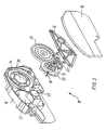
- a separate gear unit 18 is provided which is surrounded by a gear housing 19 and a cover 20.
- Fig. 3 shows the gear unit 18 disassembled, and it should be noted that the unit is here practically turned upside down relative to its mounting position in Fig. 1.
- a first toothed wheel 22 is journalled, said wheel being manufactured integrally with a bayonet catch 23 which through an aperture 25 in the back wall 24 may be connected with an input shaft not shown, said shaft being for instance driven by an electromotor or manually by means of a winding handle.
- the first toothed wheel 22 drives via an intermediate second toothed wheel 26 a third toothed wheel 21, which is integral with a drive wheel 16 journalled in an aperture 27 in the back wall 24.
- a central bayonet catch not shown for shaft connection with one or several other drive wheels 16 forms an integral part of said drive wheel 16.
- An abutment member 17, as shown in Fig. 2 forms an integral part of the side of the back wall 24 facing away and retains the armour 14 in engagement with the drive wheel 16.
- the second toothed wheel 26 further drives a fourth intermediate toothed wheel 28 driving a fifth toothed wheel 29.
- the toothed wheel 29 has a central bayonet catch 32 protruding through an aperture 30 in the back wall 24 and serving as connection for a drive shaft 31 for the tubular rod 13, see Fig.
- All the toothed wheels are kept journalled between the back wall 24 in the gear housing 19 and a gear cover 36, and all members of the gear unit 18 may advantageously be manufactured from injection moulded plastic.
- the gear unit 18 is thus a separate unit which may easily be connected with the necessary shafts which are just inserted into the bayonet catches.
- Fig. 4 will be seen how the toothed wheel 29 by means of the bayonet catch 32 is connected with the drive shaft 31.
- the drive shaft 31 is kept pivotally journalled coaxially in the tubular rod 13, said shaft extending through an end stopper 33 which is fixed at one end of the tubular rod 13.
- the drive shaft 31 is provided with a disc 34 which is in sliding abutment on the interior side of the tubular rod 13 and thus keeps the drive shaft 31 centred in the tubular rod.
- a torsion spring 35 has been wound around the drive shaft 31, one end of which spring being secured to the disc 34 and the other end of which being secured to the end stopper 33.
- the drive shaft 31 may for instance at each end of the tubular rod 13 be pivotally journalled in an end stopper, and the spring may then be secured to one end stopper and the drive shaft.
- Fig. 3 the rotational directions of the toothed wheels during unwinding of the armour 14 are indicated by arrows, the armour being unwound from the tubular rod 13 by means of the drive wheel 16, which through the gear transmission is driven by the input shaft.
- the tubular rod 13 is turned with a rotational speed which increases as the diameter of the wound armour 14 is reduced, see Fig. 2.
- the drive shaft 31 has the same rotational direction as the-tubular rod 13, and by suitable gearing of the mutually engaging toothed wheels it may be obtained that the drive shaft rotates more slowly than the tubular rod, whereby the torsion spring 35 is stressed.
- the course is the reverse, whereby the tension of the spring 35 is slackened.
- the spring may for instance have 40 windings and be prestressed for 20 revolutions, following which it is tensioned further 8 - 10 revolutions during the unwinding.
- the spring may during the unwinding be stressed a few revolutions, like for instance 2 - 3.
- a second embodiment of the gear unit according to the invention has been indicated, a belt drive being in this connection used instead of a gear transmission.
- the wheel 21 which drives the drive wheels 16, and the wheel 29, which drives the drive shaft 31, have the same directions of rotation. It is therefore necessary to let the armour 14 extend above the drive wheel 16, contrary to the embodiment shown in Fig. 2, in which it extends below the drive wheel.
- the armour might also be wound the other way around the tubular rod.
- the screening arrangement without a driving input shaft, in which case it can be wound and unwound by merely pushing or pulling the bottom slat 11.
- the wheel 16 which is termed drive wheel above, would then instead be driven by the armour 14 and via the gear transmission drive the drive shaft 31, where it would be possible to wind and unwind the armour around the tubular rod 13 in the same manner as described above.
- the invention has been exemplified by means of a roller shutter, but many other screening arrangements, like roller blinds, marquises, Venetian blinds, garage gates and the like, likewise fall within the scope of the present invention.
- the length 14 of screening material need not consist of slats, but may for instance be cloth or the like, and the drive wheel 16 may for instance be replaced by a continuous belt in contact with the length of screening material.
Landscapes
- Engineering & Computer Science (AREA)
- Structural Engineering (AREA)
- Architecture (AREA)
- Civil Engineering (AREA)
- Operating, Guiding And Securing Of Roll- Type Closing Members (AREA)
- Medicines Containing Antibodies Or Antigens For Use As Internal Diagnostic Agents (AREA)
- Investigating Or Analysing Biological Materials (AREA)
- Details Of Aerials (AREA)
- Window Of Vehicle (AREA)
- Roof Covering Using Slabs Or Stiff Sheets (AREA)
- Instruments For Viewing The Inside Of Hollow Bodies (AREA)
- Coloring Foods And Improving Nutritive Qualities (AREA)
- Non-Silver Salt Photosensitive Materials And Non-Silver Salt Photography (AREA)
- Noodles (AREA)
Abstract
Description
Claims (7)
- A screening arrangement (5) comprising a flexible length (14) of screening material, a tubular rod (13), along which one end of the length is fastened, and around which the length can be wound, and a driving device for moving the length towards or away from the tubular rod, said driving device comprising an input shaft driving a driver member (16) in driving engagement with the length (14), and in which the tubular rod (13) is connected with one end of a torsion spring (35), characterized in that the other end of the torsion spring (35) is connected with a drive shaft (31) driven by the input shaft in such a manner that by rewinding and unwinding, the drive shaft has the same direction of rotation as the tubular rod (13).
- A screening arrangement (5) according to claim 1, characterized in that the torsion spring (35) is prestressed for putting a load on the tubular rod (13) in the rewinding direction, when the length (14) of screening material is in its rewound position.
- A screening arrangement (5) according to claim 1 or 2, characterized in that the drive shaft (31) and the driver member (16) are driven at such speeds relative to each other that the speed of rotation of the tubular rod (13) during the entire rewinding or unwinding of the length (14) is higher than the speed of rotation of the drive shaft (31).
- A screening arrangement (5) according to any of the preceding claims, characterized in that the drive shaft (31) and the driver member (16) are driven by the input shaft by means of a toothed gearing.
- A screening arrangement (5) according to any of the preceding claims, characterized in that the drive shaft (31) is pivotally journalled in an end stopper (33), which is fixed at one end of the tubular rod (13), that a disc (34) is fixed at the end of the drive shaft (31) positioned in the tubular rod (13), said disc being in sliding engagement with the interior wall of the tubular rod (13), and that one end of the torsion spring (35) is secured to the disc (34) and that its other end is secured to the end stopper (33).
- A screening arrangement (5) according to any of the preceding claims, characterized in that the driving device comprises a separate gear unit (18) surrounded by a gear housing (19) and having bayonet catches for connection with the drive shaft (31) and the input shaft, as well as a drive wheel (16) having driver members along its periphery and a central bayonet catch for shaft connection with one or several other drive wheels and that the gear housing (19) is provided with abutment members (17) adapted to make the length (14) abut on the drive wheel (16) for engagement therewith.
- A screening arrangement (5) according to any of the preceding claims, characterized in that the screening arrangement (5) is a roller shutter.
Applications Claiming Priority (3)
| Application Number | Priority Date | Filing Date | Title |
|---|---|---|---|
| DK981476 | 1998-11-12 | ||
| DK199801476A DK199801476A (en) | 1998-11-12 | 1998-11-12 | A screening device |
| PCT/DK1999/000620 WO2000029706A1 (en) | 1998-11-12 | 1999-11-11 | A screening arrangement |
Publications (3)
| Publication Number | Publication Date |
|---|---|
| EP1131530A1 EP1131530A1 (en) | 2001-09-12 |
| EP1131530B1 true EP1131530B1 (en) | 2002-09-18 |
| EP1131530B8 EP1131530B8 (en) | 2003-03-19 |
Family
ID=8105235
Family Applications (1)
| Application Number | Title | Priority Date | Filing Date |
|---|---|---|---|
| EP99972285A Expired - Lifetime EP1131530B8 (en) | 1998-11-12 | 1999-11-11 | A screening arrangement |
Country Status (10)
| Country | Link |
|---|---|
| EP (1) | EP1131530B8 (en) |
| CN (1) | CN1127610C (en) |
| AT (1) | ATE224503T1 (en) |
| AU (1) | AU1150900A (en) |
| DE (1) | DE69903060T2 (en) |
| DK (1) | DK199801476A (en) |
| HU (1) | HU222958B1 (en) |
| PL (1) | PL191038B1 (en) |
| SK (1) | SK286216B6 (en) |
| WO (1) | WO2000029706A1 (en) |
Families Citing this family (4)
| Publication number | Priority date | Publication date | Assignee | Title |
|---|---|---|---|---|
| CN102041964B (en) * | 2009-10-14 | 2012-08-22 | 昆山皇田汽车配件工业有限公司 | Rolling rod for rolling type cover curtain |
| DE202011105060U1 (en) * | 2011-08-31 | 2011-10-27 | Alfred Schellenberg Gmbh | Adapter for the output shaft of a tubular drive device for winding and unwinding a darkening device, in particular a roller shutter or the like. |
| PL240870B1 (en) * | 2017-08-07 | 2022-06-20 | Fakro Pp Spolka Z Ograniczona Odpowiedzialnoscia | Driving unit of a roller blind, preferably the strip jalousie |
| CN115769950B (en) * | 2022-12-28 | 2024-09-17 | 慕思健康睡眠股份有限公司 | Spareribs frame and bedstead |
Family Cites Families (8)
| Publication number | Priority date | Publication date | Assignee | Title |
|---|---|---|---|---|
| US2183495A (en) * | 1937-01-06 | 1939-12-12 | Gen Door Company | Flexible rolling curtain |
| FR2418860A1 (en) * | 1978-03-02 | 1979-09-28 | Sarvot Maurice | Winding gear for window blind of plastics sheet - has boxed coordinated endless belts guiding sheet edges which include holes engaged by belt studs |
| DE2947501A1 (en) * | 1979-11-24 | 1981-05-27 | Siegfried 7410 Reutlingen Bauer | RETRACTABLE AND EXTENDABLE COVER, IN PARTICULAR ROLLER SHUTTERS FOR WINDOWS, DOORS, GATES OR THE LIKE. |
| DE3480104D1 (en) * | 1983-11-21 | 1989-11-16 | Richard Bubendorff | Roller shutter |
| DE3661488D1 (en) * | 1985-10-23 | 1989-01-26 | Richard Bubendorff | Roller shutter for an attic window |
| FR2614928B1 (en) * | 1987-05-06 | 1992-01-10 | Bubendorff Richard | ROLLER SHUTTER FOR DOOR, WINDOW AND OTHER OPENINGS |
| NL8802968A (en) * | 1988-12-01 | 1990-07-02 | Polynorm Nv | DOOR. |
| DE19655108B4 (en) * | 1996-01-12 | 2004-11-04 | Roto Frank Ag | Roller shutters for windows, doors or the like |
-
1998
- 1998-11-12 DK DK199801476A patent/DK199801476A/en not_active Application Discontinuation
-
1999
- 1999-11-11 HU HU0104114A patent/HU222958B1/en not_active IP Right Cessation
- 1999-11-11 AU AU11509/00A patent/AU1150900A/en not_active Abandoned
- 1999-11-11 SK SK645-2001A patent/SK286216B6/en unknown
- 1999-11-11 EP EP99972285A patent/EP1131530B8/en not_active Expired - Lifetime
- 1999-11-11 PL PL347657A patent/PL191038B1/en unknown
- 1999-11-11 CN CN99813163A patent/CN1127610C/en not_active Expired - Fee Related
- 1999-11-11 DE DE69903060T patent/DE69903060T2/en not_active Expired - Lifetime
- 1999-11-11 AT AT99972285T patent/ATE224503T1/en not_active IP Right Cessation
- 1999-11-11 WO PCT/DK1999/000620 patent/WO2000029706A1/en not_active Ceased
Also Published As
| Publication number | Publication date |
|---|---|
| SK286216B6 (en) | 2008-05-06 |
| CN1326529A (en) | 2001-12-12 |
| HUP0104114A3 (en) | 2003-02-28 |
| EP1131530B8 (en) | 2003-03-19 |
| ATE224503T1 (en) | 2002-10-15 |
| SK6452001A3 (en) | 2001-12-03 |
| CN1127610C (en) | 2003-11-12 |
| AU1150900A (en) | 2000-06-05 |
| HU222958B1 (en) | 2004-01-28 |
| EP1131530A1 (en) | 2001-09-12 |
| DE69903060D1 (en) | 2002-10-24 |
| PL347657A1 (en) | 2002-04-22 |
| DK199801476A (en) | 2000-05-13 |
| PL191038B1 (en) | 2006-03-31 |
| HUP0104114A2 (en) | 2002-03-28 |
| WO2000029706A1 (en) | 2000-05-25 |
| DE69903060T2 (en) | 2003-05-08 |
Similar Documents
| Publication | Publication Date | Title |
|---|---|---|
| US6257305B1 (en) | Method and apparatus for driving and storing a covering | |
| US6530414B2 (en) | Insulating glass pane comprising an integrated roller blind device | |
| US5479979A (en) | Screen device | |
| US5129442A (en) | Roll-up industrial door having a combined pulley for counterweight and spring tension belts | |
| CA1286591C (en) | Apparatus for opening and closing roll-up door | |
| CN1121544C (en) | Outer shades for swivel sunroofs | |
| CN100510292C (en) | Roller curtain device | |
| US20070163727A1 (en) | Window Blinds with Gears | |
| JPH11270089A (en) | Sunshade roll screen | |
| KR102647581B1 (en) | Awnings and resulting spring driven systems | |
| GB2166480A (en) | Roller apparatus | |
| WO1985000633A1 (en) | Tensioning device intended to the rolling and unrolling of a protection element | |
| KR840002808Y1 (en) | Apparatus for opening and closing the seat of green house | |
| SK6462001A3 (en) | Drainage gutter | |
| JP2002089154A (en) | Blind apparatus and double glazing with built-in blind | |
| CN217561903U (en) | Optical lens window protection mechanism | |
| EP1131530A1 (en) | A screening arrangement | |
| EP0117116A2 (en) | Roller door | |
| CA2397549C (en) | A method and apparatus for driving and storing a covering | |
| JP2699857B2 (en) | Drive devices such as shutters | |
| BE1015160A3 (en) | Sunshade opening and closing device, e.g. for triangular or trapezoidal windows, includes torsion spring attached to sunshade cloth and winding shaft | |
| EP0801206A2 (en) | Vertically-moving roller curtain for windows in general and particularly for rail passenger-car windows | |
| SU900842A1 (en) | Curtain | |
| JP2004324409A (en) | Method and device for driving and housing covering object | |
| JP2004324408A (en) | Method and device for driving and housing covering object |
Legal Events
| Date | Code | Title | Description |
|---|---|---|---|
| PUAI | Public reference made under article 153(3) epc to a published international application that has entered the european phase |
Free format text: ORIGINAL CODE: 0009012 |
|
| 17P | Request for examination filed |
Effective date: 20010427 |
|
| AK | Designated contracting states |
Kind code of ref document: A1 Designated state(s): AT BE CH CY DE DK ES FI FR GB GR IE IT LI LU |
|
| AX | Request for extension of the european patent |
Free format text: AL PAYMENT 20010427;LT PAYMENT 20010427;LV PAYMENT 20010427;MK PAYMENT 20010427;RO PAYMENT 20010427;SI PAYMENT 20010427 |
|
| GRAG | Despatch of communication of intention to grant |
Free format text: ORIGINAL CODE: EPIDOS AGRA |
|
| 17Q | First examination report despatched |
Effective date: 20020218 |
|
| GRAG | Despatch of communication of intention to grant |
Free format text: ORIGINAL CODE: EPIDOS AGRA |
|
| GRAH | Despatch of communication of intention to grant a patent |
Free format text: ORIGINAL CODE: EPIDOS IGRA |
|
| GRAH | Despatch of communication of intention to grant a patent |
Free format text: ORIGINAL CODE: EPIDOS IGRA |
|
| GRAA | (expected) grant |
Free format text: ORIGINAL CODE: 0009210 |
|
| AK | Designated contracting states |
Kind code of ref document: B1 Designated state(s): AT BE CH CY DE DK ES FI FR GB GR IE IT LI LU |
|
| AX | Request for extension of the european patent |
Free format text: AL PAYMENT 20010427;LT PAYMENT 20010427;LV PAYMENT 20010427;MK PAYMENT 20010427;RO PAYMENT 20010427;SI PAYMENT 20010427 |
|
| PG25 | Lapsed in a contracting state [announced via postgrant information from national office to epo] |
Ref country code: SE Free format text: LAPSE BECAUSE OF FAILURE TO SUBMIT A TRANSLATION OF THE DESCRIPTION OR TO PAY THE FEE WITHIN THE PRESCRIBED TIME-LIMIT Effective date: 20020918 Ref country code: LI Free format text: LAPSE BECAUSE OF FAILURE TO SUBMIT A TRANSLATION OF THE DESCRIPTION OR TO PAY THE FEE WITHIN THE PRESCRIBED TIME-LIMIT Effective date: 20020918 Ref country code: IT Free format text: LAPSE BECAUSE OF FAILURE TO SUBMIT A TRANSLATION OF THE DESCRIPTION OR TO PAY THE FEE WITHIN THE PRESCRIBED TIME-LIMIT;WARNING: LAPSES OF ITALIAN PATENTS WITH EFFECTIVE DATE BEFORE 2007 MAY HAVE OCCURRED AT ANY TIME BEFORE 2007. THE CORRECT EFFECTIVE DATE MAY BE DIFFERENT FROM THE ONE RECORDED. Effective date: 20020918 Ref country code: GR Free format text: LAPSE BECAUSE OF FAILURE TO SUBMIT A TRANSLATION OF THE DESCRIPTION OR TO PAY THE FEE WITHIN THE PRESCRIBED TIME-LIMIT Effective date: 20020918 Ref country code: FI Free format text: LAPSE BECAUSE OF FAILURE TO SUBMIT A TRANSLATION OF THE DESCRIPTION OR TO PAY THE FEE WITHIN THE PRESCRIBED TIME-LIMIT Effective date: 20020918 Ref country code: CH Free format text: LAPSE BECAUSE OF FAILURE TO SUBMIT A TRANSLATION OF THE DESCRIPTION OR TO PAY THE FEE WITHIN THE PRESCRIBED TIME-LIMIT Effective date: 20020918 Ref country code: BE Free format text: LAPSE BECAUSE OF FAILURE TO SUBMIT A TRANSLATION OF THE DESCRIPTION OR TO PAY THE FEE WITHIN THE PRESCRIBED TIME-LIMIT Effective date: 20020918 Ref country code: AT Free format text: LAPSE BECAUSE OF FAILURE TO SUBMIT A TRANSLATION OF THE DESCRIPTION OR TO PAY THE FEE WITHIN THE PRESCRIBED TIME-LIMIT Effective date: 20020918 |
|
| REF | Corresponds to: |
Ref document number: 224503 Country of ref document: AT Date of ref document: 20021015 Kind code of ref document: T |
|
| REG | Reference to a national code |
Ref country code: GB Ref legal event code: FG4D |
|
| REG | Reference to a national code |
Ref country code: CH Ref legal event code: EP |
|
| REG | Reference to a national code |
Ref country code: IE Ref legal event code: FG4D |
|
| REF | Corresponds to: |
Ref document number: 69903060 Country of ref document: DE Date of ref document: 20021024 |
|
| PG25 | Lapsed in a contracting state [announced via postgrant information from national office to epo] |
Ref country code: LU Free format text: LAPSE BECAUSE OF NON-PAYMENT OF DUE FEES Effective date: 20021111 Ref country code: IE Free format text: LAPSE BECAUSE OF NON-PAYMENT OF DUE FEES Effective date: 20021111 |
|
| PG25 | Lapsed in a contracting state [announced via postgrant information from national office to epo] |
Ref country code: CY Free format text: LAPSE BECAUSE OF FAILURE TO SUBMIT A TRANSLATION OF THE DESCRIPTION OR TO PAY THE FEE WITHIN THE PRESCRIBED TIME-LIMIT Effective date: 20021130 |
|
| PG25 | Lapsed in a contracting state [announced via postgrant information from national office to epo] |
Ref country code: DK Free format text: LAPSE BECAUSE OF FAILURE TO SUBMIT A TRANSLATION OF THE DESCRIPTION OR TO PAY THE FEE WITHIN THE PRESCRIBED TIME-LIMIT Effective date: 20021218 |
|
| LTIE | Lt: invalidation of european patent or patent extension |
Effective date: 20020918 |
|
| RBV | Designated contracting states (corrected) |
Designated state(s): AT BE CH CY DE DK ES FI FR GB GR IE IT LI LU MC NL PT SE |
|
| PG25 | Lapsed in a contracting state [announced via postgrant information from national office to epo] |
Ref country code: ES Free format text: LAPSE BECAUSE OF FAILURE TO SUBMIT A TRANSLATION OF THE DESCRIPTION OR TO PAY THE FEE WITHIN THE PRESCRIBED TIME-LIMIT Effective date: 20030328 |
|
| REG | Reference to a national code |
Ref country code: CH Ref legal event code: PL |
|
| ET | Fr: translation filed | ||
| PG25 | Lapsed in a contracting state [announced via postgrant information from national office to epo] |
Ref country code: MC Free format text: LAPSE BECAUSE OF NON-PAYMENT OF DUE FEES Effective date: 20030601 |
|
| PLBE | No opposition filed within time limit |
Free format text: ORIGINAL CODE: 0009261 |
|
| STAA | Information on the status of an ep patent application or granted ep patent |
Free format text: STATUS: NO OPPOSITION FILED WITHIN TIME LIMIT |
|
| REG | Reference to a national code |
Ref country code: IE Ref legal event code: MM4A |
|
| 26N | No opposition filed |
Effective date: 20030619 |
|
| PG25 | Lapsed in a contracting state [announced via postgrant information from national office to epo] |
Ref country code: GB Free format text: LAPSE BECAUSE OF NON-PAYMENT OF DUE FEES Effective date: 20031111 |
|
| GBPC | Gb: european patent ceased through non-payment of renewal fee |
Effective date: 20031111 |
|
| PG25 | Lapsed in a contracting state [announced via postgrant information from national office to epo] |
Ref country code: PT Free format text: LAPSE BECAUSE OF NON-PAYMENT OF DUE FEES Effective date: 20030218 |
|
| PGFP | Annual fee paid to national office [announced via postgrant information from national office to epo] |
Ref country code: NL Payment date: 20141108 Year of fee payment: 16 |
|
| REG | Reference to a national code |
Ref country code: FR Ref legal event code: PLFP Year of fee payment: 17 |
|
| REG | Reference to a national code |
Ref country code: NL Ref legal event code: MM Effective date: 20151201 |
|
| PG25 | Lapsed in a contracting state [announced via postgrant information from national office to epo] |
Ref country code: NL Free format text: LAPSE BECAUSE OF NON-PAYMENT OF DUE FEES Effective date: 20151201 |
|
| REG | Reference to a national code |
Ref country code: FR Ref legal event code: PLFP Year of fee payment: 18 |
|
| REG | Reference to a national code |
Ref country code: FR Ref legal event code: PLFP Year of fee payment: 19 |
|
| PGFP | Annual fee paid to national office [announced via postgrant information from national office to epo] |
Ref country code: DE Payment date: 20171108 Year of fee payment: 19 Ref country code: FR Payment date: 20171026 Year of fee payment: 19 |
|
| REG | Reference to a national code |
Ref country code: DE Ref legal event code: R119 Ref document number: 69903060 Country of ref document: DE |
|
| PG25 | Lapsed in a contracting state [announced via postgrant information from national office to epo] |
Ref country code: DE Free format text: LAPSE BECAUSE OF NON-PAYMENT OF DUE FEES Effective date: 20190601 Ref country code: FR Free format text: LAPSE BECAUSE OF NON-PAYMENT OF DUE FEES Effective date: 20181130 |