EP1130949A1 - Dispositif électromagnetique pour la production d'atomes froids - Google Patents
Dispositif électromagnetique pour la production d'atomes froids Download PDFInfo
- Publication number
- EP1130949A1 EP1130949A1 EP01400460A EP01400460A EP1130949A1 EP 1130949 A1 EP1130949 A1 EP 1130949A1 EP 01400460 A EP01400460 A EP 01400460A EP 01400460 A EP01400460 A EP 01400460A EP 1130949 A1 EP1130949 A1 EP 1130949A1
- Authority
- EP
- European Patent Office
- Prior art keywords
- poles
- production
- electromagnetic device
- neutral atoms
- atoms according
- Prior art date
- Legal status (The legal status is an assumption and is not a legal conclusion. Google has not performed a legal analysis and makes no representation as to the accuracy of the status listed.)
- Granted
Links
Images



Classifications
-
- H—ELECTRICITY
- H05—ELECTRIC TECHNIQUES NOT OTHERWISE PROVIDED FOR
- H05H—PLASMA TECHNIQUE; PRODUCTION OF ACCELERATED ELECTRICALLY-CHARGED PARTICLES OR OF NEUTRONS; PRODUCTION OR ACCELERATION OF NEUTRAL MOLECULAR OR ATOMIC BEAMS
- H05H3/00—Production or acceleration of neutral particle beams, e.g. molecular or atomic beams
- H05H3/02—Molecular or atomic-beam generation, e.g. resonant beam generation
Definitions
- the present invention relates to the field of production of cold neutral atoms by magnetic trapping.
- the invention relates more particularly to a electromagnetic device for the production of atoms cold neutrals comprising a ferromagnetic structure with 4 poles arranged in the same excited XOY plane by main coils (the quadrupole) providing the main excitation, and two additional poles (the dipole) oriented along a Z axis perpendicular to the plane of said four poles, the poles being coupled magnetically by one or more cylinder heads.
- main coils the quadrupole
- the dipole the dipole
- the invention relates in its most general sense to a device having additional poles constituted by a excited external structure and internal structure separately by two coils traversed by currents contrary.
- This device constitutes an Ioffé-Pritchard trap with bias compensated for trapping and / or creation of a coherent source of cold atoms (Bose-Einstein condensates), allowing to realize high compression rates with low consumption electric. It allows continuous or pulsed operation with cut-off times of 100 microseconds. It allows also an adjustment of the magnetic fields produced by the different coils by adjusting the current browsing the excitation coils.
- the additional poles are formed by a substantially cylindrical core having a end hollowed out by an annular cavity coaxial with inside which the excitation coil is housed interior.
- certain poles at least have a sleeve with a tubular channel for circulation of a thermoregulation fluid.
- said sleeve is surrounded by the compensation coil.
- the cylinder heads are made up a first annular element extending over 180 ° extended to each end by second annular elements extending over 90 °, in a plane perpendicular to the plane of the first element, each of said second annular elements being coupled to an annular element extending over 180 ° in a plane perpendicular to the other elements annulars.
- the cylinder heads and poles are made of a material ferromagnetic limiting the eddy currents, in particular a laminated ferromagnetic material or sintered materials.
- the cylinder head has a annular lamination perpendicular to the lamination of poles.
- the end of certain poles at the less has a beveled shape.
- Figure 1 shows a view of a first variant.
- the device consists of two elements of two torus-shaped cylinder heads (1, 2), and by six elements polar (3 to 8) radial.
- the cylinder heads (1, 2) are formed by winding a strip of ferromagnetic material.
- the cylinder heads have different radii to allow fitting the inner cylinder head into the cylinder head exterior, the two cylinder heads (1, 2) having planes perpendicular medians.
- the first cylinder head (1) is placed in the YOZ plane.
- the second cylinder head (2) is placed in the XOZ plane.
- the four poles (3,5,7,8) are placed in the XOY plane. They are formed by a nucleus ferromagnetic made of a laminated material, surrounded by a coil (13,17,15,18) in copper tube providing the main excitation, and by an additional coil not shown in the figure, providing a field of compensation of residual fields.
- the last two poles (4, 6) are oriented along the Z axis and consist of a ferromagnetic core made of a laminated material surrounded by an external coil (14 and 16). These two poles (4, 6) further include an internal coil (27, 28) traversed by a current in the opposite direction to the current flowing through the external coil.
- the external structure creates a field of the same shape which will make it possible to compensate B 0 while retaining a high value for C.
- the device also comprises a quadrupole (3, 5, 7, 8) a dipole formed by the two poles (4,6) arranged along the z axis,
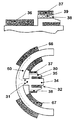
- Figure 2 shows a view detailed, in longitudinal section.
- the purpose of this dipole is compensation for the constant field at the center of the trap to produce significant containment, and allowing obtain pulse rates greater than 0.01 hertz, of the order of hertz.
- the poles of the dipole have a core (31) laminated have a frustoconical end (30).
- the core has an axial cavity (32) of annular shape in which a coil is housed electric (35) surrounding a cylindrical core (31).
- the main core (31) is surrounded by a first main coil (14, 16) (Fig. 1) and a coil compensation of the residual fields (37).
- the main coils (36) and the coil internal (35) are supplied in series and in opposition by pulse mode.
- the coils of one of the poles and the coils of the complementary pole opposite are itself connected for a series supply, in the same direction and no longer in opposition.
- the secondary field compensation coil retentive (37) is mounted on a structure of annular thermostabilization (38), surrounding the central part of the pole (31).
- This annular structure (38) has an annular channel (39) for circulation of a thermostatically controlled fluid.
- All of the coils are powered by a impulse current of the order of 150 W to produce a gradient of around 2400 gauss per centimeter, with a merit factor F of the order of 80,000.
- the inter-pole distance is around 4 centimeters.
- the diameter of the poles is around 20 millimeters.
- a cylindrical cell with a diameter of 25 millimeters is placed in this space.
- Figure 2 shows a variant of creation of a trapping structure for cold atoms.
- the ferromagnetic structure is composed of two semicircular rings (50, 51) arranged in perpendicular planes. These two arches (50, 51) are connected by arches (52, 53) in a quarter circle whose ends are respectively coupled to the ends of semi-circular arches (50, 51). These arches (52, 53) in quarter circle are in a third plane XOY perpendicular to the intersection of the two above-mentioned planes.
- the structure comprising 4 main poles (54 to 57) XOY quadrupoles excited by coils (58, 59) powered by currents in the same direction, the coils (58, 59) surrounding the arches (52, 53) in a quarter of a circle.
- the semi-circular arches (50, 51) are each coupled with an additional pole (60, 61) extending radially. These poles (60, 61) are surrounded by a heat stabilizing structure.
- the main excitement is supplied by the coils (66, 67) and (68, 69) distributed over the semicircular arch (50, 51) on either side of the secondary pole (60, 61). They are crossed by contrary currents.
- the devices according to the invention make it possible to generate a very steep, adjustable magnetic potential.
- Figure 4 shows an example of equipment using a device according to one or other of the variants of the invention.
- the equipment includes a recirculation oven (100) heated to about 140 ° C to produce a jet of 87 Rb atoms.
- a 2D optical molasses produced by a transverse laser beam produces the collimation of the jet and makes it possible to orient it in the axis of a tube (101).
- This tube (101) opens into a primary enclosure (102) connected to a vacuum pump (103).
- the pressure P 1 prevailing in the enclosure (102) is approximately 10 -9 millibar.
- the pump is a turbo pump with a high compression ratio (greater than 19 9 for nitrogen).
- the enclosure (102) is provided with a cold cathode gauge (105) for measuring the pressure.
- Molasses is obtained by laser diodes of power 50 to 100 mW and a master laser of 3.5 mW at 780 nm with a line width of 1 MHz.
- a cold cylinder is positioned in the enclosure, to ensure the bonding of atoms not collimated. It is formed by a metal block pierced with a 10 millimeter diameter hole. It only lets through the atoms of the jet emitted on the axis. This cylinder is cooled by a plunger (106) which ensures circulation ethylene glycol at -55 ° C.
- a valve (107) isolates the enclosure secondary.
- An ion pump (108) provides vacuum intermediate through a slowdown tube (109). This slowdown tube (109) allows to isolate thermally the oven (100) of the secondary enclosure (112).
- the secondary enclosure (112) consists of a cell glass of 1x2 cm connected to an ion pump (113) and a titanium enhancer. The walls are periodically heated to compensate for the formation of vapor from the Rubidium.
- the electromagnetic trap (120) according to the invention is placed at the outlet of a retarder (118) comprising an electric coil (119).
- Figure 5 shows the time sequence equipment.
- the different stages of a operation are synchronized.
- the quadrupole field spherical produced by the main poles is interrupted and the trap beam disagreement is increased prior to switching off the decompressor harness. During of this sequence, the lateral repumping beams remain on.
Landscapes
- Physics & Mathematics (AREA)
- Spectroscopy & Molecular Physics (AREA)
- Engineering & Computer Science (AREA)
- Plasma & Fusion (AREA)
- Particle Accelerators (AREA)
- Physical Or Chemical Processes And Apparatus (AREA)
- Electromagnets (AREA)
Abstract
Description
- la figure 1 représente une vue schématique d'une première variante de réalisation d'un dispositif selon l'invention ;
- la figure 2 représente une vue en coupe médiane d'un pôle additionnel, à une échelle agrandie ;
- la figure 3 représente une variante de réalisation d'un dispositif selon l'invention.
- la figure 4 représente une vue schématique d'un équipement mettant en oeuvre un dispositif selon l'invention.
- la figure 5 représente le cycle de fonctionnement d'un dispositif selon l'invention.

Claims (10)
- Dispositif électromagnétique pour la production d'atomes neutres froids comprenant une structure ferromagnétique présentant 4 pôles disposés dans un même plan XOY excités par des bobines principales fournissant l'excitation principale, et deux pôles additionnels orientés selon un axe Z perpendiculaires au plan desdits quatre pôles, les pôles étant couplés magnétiquement par une ou plusieurs culasses, caractérisé en ce que lesdits pôles additionnels sont constitués par une structure externe et d'une structure interne excités séparément par deux bobines parcourues par des courants contraires.
- Dispositif électromagnétique pour la production d'atomes neutres froids selon la revendication 1 caractérisé en ce que les pôles additionnels sont formés par un noyau sensiblement cylindrique présentant une extrémité creusée par une cavité annulaire coaxiale à l'intérieure de laquelle est logée la bobine d'excitation intérieure.
- Dispositif électromagnétique pour la production d'atomes neutres froids selon la revendication 1 ou 2 caractérisé en ce que certains pôles au moins présentant un manchon pourvu d'un canal tubulaire pour la circulation d'un fluide de thermorégulation.
- Dispositif électromagnétique pour la production d'atomes neutres froids selon la revendication 3 caractérisé en ce que certains pôles au moins sont entourés par une bobine de compensation des champs rémanents.
- Dispositif électromagnétique pour la production d'atomes neutres froids selon l'une quelconque des revendications précédentes caractérisé en ce que les culasses sont constituées par deux éléments annulaires de rayon Rint et Rext avec Rext = Rint + E où E désigne l'épaisseur de la culasse, les deux éléments étant emboítables et positionnés dans deux plans perpendiculaires.
- Dispositif électromagnétique pour la production d'atomes neutres froids selon l'une quelconque des revendications précédentes caractérisé en ce que la culasse est constituée un premier élément annulaire s'étendant sur 180° prolongé à chaque extrémité par des seconds éléments annulaires s'étendant sur 90°, dans un plan perpendiculaire au plan du premier élément, chacun desdits seconds éléments annulaires étant couplés à un élément annulaire s'étendant sur 180° dans un plan perpendiculaire aux autres éléments annulaires.
- Dispositif électromagnétique pour la production d'atomes neutres froids selon la revendication précédente caractérisé en ce que les seconds éléments annulaires s'étendant sur 90° sont entourés chacun par une bobine d'excitation des pôles principaux.
- Dispositif électromagnétique pour la production d'atomes neutres froids selon l'une quelconque des revendications précédentes caractérisé en ce que les culasses et les pôles sont constitués en un matériau limitant les courants de Foucault.
- Dispositif électromagnétique pour la production d'atomes neutres froids selon l'une quelconque des revendications précédentes caractérisé en ce que l'extrémité de certains pôles au moins présente une forme tronconique.
- Dispositif électromagnétique pour la production d'atomes neutres froids selon l'une quelconque des revendications précédentes caractérisé en ce que les pôles présentent en outre des bobines secondaires pour la compensation des champs rémanents.
Applications Claiming Priority (2)
| Application Number | Priority Date | Filing Date | Title |
|---|---|---|---|
| FR0002704 | 2000-03-02 | ||
| FR0002704A FR2805959B1 (fr) | 2000-03-02 | 2000-03-02 | Dispositif electromagnetique pour la production d'atomes neutres froids |
Publications (2)
| Publication Number | Publication Date |
|---|---|
| EP1130949A1 true EP1130949A1 (fr) | 2001-09-05 |
| EP1130949B1 EP1130949B1 (fr) | 2005-09-07 |
Family
ID=8847657
Family Applications (1)
| Application Number | Title | Priority Date | Filing Date |
|---|---|---|---|
| EP01400460A Expired - Lifetime EP1130949B1 (fr) | 2000-03-02 | 2001-02-22 | Dispositif électromagnetique pour la production d'atomes froids |
Country Status (4)
| Country | Link |
|---|---|
| US (1) | US6548809B2 (fr) |
| EP (1) | EP1130949B1 (fr) |
| DE (1) | DE60113171T2 (fr) |
| FR (1) | FR2805959B1 (fr) |
Cited By (1)
| Publication number | Priority date | Publication date | Assignee | Title |
|---|---|---|---|---|
| EP2104406A1 (fr) | 2008-03-19 | 2009-09-23 | Ixsea | Source d'atome cohérente guidée et interféromètre atomique |
Families Citing this family (18)
| Publication number | Priority date | Publication date | Assignee | Title |
|---|---|---|---|---|
| DE10220757B4 (de) * | 2002-05-08 | 2004-06-24 | Westfalia Separator Ag | Zentrifuge, insbesondere Separator |
| US7126112B2 (en) * | 2004-03-10 | 2006-10-24 | Anderson Dana Z | Cold atom system with atom chip wall |
| CN1333622C (zh) * | 2004-12-02 | 2007-08-22 | 清华大学 | 一种冷原子束产生方法及其装置 |
| CN100376123C (zh) * | 2005-01-13 | 2008-03-19 | 清华大学 | 一种原子芯片用原子束发生方法及其装置 |
| JP4862202B2 (ja) * | 2006-03-08 | 2012-01-25 | 独立行政法人情報通信研究機構 | 中性原子のトラップ装置 |
| US7709807B2 (en) * | 2007-05-31 | 2010-05-04 | United States Of America As Represented By The Secretary Of Commerce, The National Institute Of Standards And Technology | Magneto-optical trap ion source |
| FR2928725B1 (fr) * | 2008-03-12 | 2010-04-09 | Centre Nat Rech Scient | Capteur interferometrique a atomes froids |
| US8237105B1 (en) | 2011-02-03 | 2012-08-07 | Northrop Grumman Guidance & Electronics Company, Inc. | Magneto-optical trap for cold atom beam source |
| US9134450B2 (en) | 2013-01-07 | 2015-09-15 | Muquans | Cold atom gravity gradiometer |
| US10446307B2 (en) * | 2017-05-23 | 2019-10-15 | AOSense, Inc. | Magnetic field generators based on high magnetic permeability materials |
| CN108770177B (zh) * | 2018-07-16 | 2019-08-20 | 北京航空航天大学 | 空芯反共振光纤冷原子束流导引与通量探测方法及装置 |
| US11580435B2 (en) | 2018-11-13 | 2023-02-14 | Atom Computing Inc. | Scalable neutral atom based quantum computing |
| US10504033B1 (en) | 2018-11-13 | 2019-12-10 | Atom Computing Inc. | Scalable neutral atom based quantum computing |
| US11995512B2 (en) | 2018-11-13 | 2024-05-28 | Atom Computing Inc. | Scalable neutral atom based quantum computing |
| EP4115351A4 (fr) | 2020-03-02 | 2024-05-08 | Atom Computing Inc. | Calcul quantique basé sur les atomes neutres évolutif |
| CN115516469B (zh) | 2020-03-02 | 2026-05-01 | 原子计算公司 | 可扩展的基于中性原子的量子计算 |
| US12046387B2 (en) | 2020-09-16 | 2024-07-23 | ColdQuanta, Inc. | Vacuum cell with integrated guide stack wall |
| EP4526813A4 (fr) | 2022-05-19 | 2026-05-06 | Atom Computing Inc | Dispositifs et procédés de calcul à base de cavités |
Family Cites Families (1)
| Publication number | Priority date | Publication date | Assignee | Title |
|---|---|---|---|---|
| US6476383B1 (en) * | 1999-08-31 | 2002-11-05 | Max-Planck-Gesellschaft Zur Forderung Der Wissenschaften E.V. | Device and method for generating and manipulating coherent matter waves |
-
2000
- 2000-03-02 FR FR0002704A patent/FR2805959B1/fr not_active Expired - Fee Related
-
2001
- 2001-02-22 DE DE60113171T patent/DE60113171T2/de not_active Expired - Lifetime
- 2001-02-22 EP EP01400460A patent/EP1130949B1/fr not_active Expired - Lifetime
- 2001-03-02 US US09/796,698 patent/US6548809B2/en not_active Expired - Fee Related
Non-Patent Citations (3)
| Title |
|---|
| DESRUELLE B ET AL: "TRAPPING COLD NEUTRAL ATOMS WITH AN IRON-CORE ELECTROMAGNET", EUROPEAN PHYSICAL JOURNAL D: ATOMS, MOLECULES, CLUSTERS AND OPTICAL PHYSICS,EDP SCIENCES, LES ULIS,,FR, 1998, pages 255 - 258, XP000937558, ISSN: 1434-6060 * |
| ESSLINGER T ET AL: "Bose-Einstein condensation in a quadrupole-Ioffe-configuration trap", PHYSICAL REVIEW A (ATOMIC, MOLECULAR, AND OPTICAL PHYSICS), OCT. 1998, APS THROUGH AIP, USA, vol. 58, no. 4, pages R2664 - R2667, XP000953007, ISSN: 1050-2947 * |
| TOLLET J J ET AL: "PERMANENT MAGNET TRAP FOR COLD ATOMS", PHYSICAL REVIEW, A. GENERAL PHYSICS,AMERICAN INSTITUTE OF PHYSICS. NEW YORK,US, vol. 51, no. 1, January 1995 (1995-01-01), pages R22 - R25, XP000938673, ISSN: 1050-2947 * |
Cited By (2)
| Publication number | Priority date | Publication date | Assignee | Title |
|---|---|---|---|---|
| EP2104406A1 (fr) | 2008-03-19 | 2009-09-23 | Ixsea | Source d'atome cohérente guidée et interféromètre atomique |
| US8288712B2 (en) | 2008-03-19 | 2012-10-16 | Ixsea | Guided coherent atom source and atomic interferometer |
Also Published As
| Publication number | Publication date |
|---|---|
| US20010042824A1 (en) | 2001-11-22 |
| EP1130949B1 (fr) | 2005-09-07 |
| US6548809B2 (en) | 2003-04-15 |
| DE60113171T2 (de) | 2006-06-22 |
| FR2805959B1 (fr) | 2002-04-12 |
| FR2805959A1 (fr) | 2001-09-07 |
| DE60113171D1 (de) | 2005-10-13 |
Similar Documents
| Publication | Publication Date | Title |
|---|---|---|
| EP1130949B1 (fr) | Dispositif électromagnetique pour la production d'atomes froids | |
| EP0662195B1 (fr) | Moteur a plasma de longueur reduite a derive fermee d'electrons | |
| EP0650557B1 (fr) | Moteur a plasma a derive fermee d'electrons | |
| EP0222786B1 (fr) | Cyclotron | |
| WO1988009597A1 (fr) | Accelerateur d'electrons a cavite coaxiale | |
| EP0248689A1 (fr) | Klystron à faisceaux multiples | |
| EP2591643A1 (fr) | Cyclotron comprenant un moyen de modification du profil de champ magnétique et procédé associé | |
| JPH07118573B2 (ja) | 軟x線レーザ発生方法およびその装置 | |
| Sjobak et al. | Strong focusing gradient in a linear active plasma lens | |
| WO2014131994A1 (fr) | Dispositif de magnetisation de plasma laser par champ magnetique pulse | |
| CA2687070A1 (fr) | Actionneur electromagnetique a reluctance variable | |
| US5784397A (en) | Bulk semiconductor lasers at submillimeter/far infrared wavelengths using a regular permanent magnet | |
| EP0204742A1 (fr) | Aimant solenoidal a champ magnetique homogene | |
| CA2576774A1 (fr) | Piege a ions a aimant permanent longitudinal et spectrometre de masse utilisant un tel aimant | |
| EP0298817B1 (fr) | Procédé et dispositif de production d'électrons utilisant un couplage de champ et l'effet photoélectrique | |
| Fournier et al. | Novel laser ion sources | |
| FR2651406A1 (fr) | Laser a electrons libres. | |
| FR2702663A1 (fr) | Installation de protonthérapie. | |
| Döbele et al. | On scattering diagnostics with periodically pulsed lasers to follow the continuous evolution of time dependent plasma parameters | |
| FR2633389A1 (fr) | Gyroscope a laser a anneau | |
| Thakur | Understanding plasmas through ion velocity distribution function measurements | |
| FR2737834A1 (fr) | Accelerateur lineaire de protons pour hadrontherapie | |
| EP0813223A1 (fr) | Dispositif pour engendrer un champ magnétique et source ecr comportant ce dispositif | |
| FR2766049A1 (fr) | Cyclotron compact et son utilisation en proton-therapie | |
| FR2558994A1 (fr) | Generateur laser a flux gazeux |
Legal Events
| Date | Code | Title | Description |
|---|---|---|---|
| PUAI | Public reference made under article 153(3) epc to a published international application that has entered the european phase |
Free format text: ORIGINAL CODE: 0009012 |
|
| 17P | Request for examination filed |
Effective date: 20010316 |
|
| AK | Designated contracting states |
Kind code of ref document: A1 Designated state(s): AT BE CH CY DE DK ES FI FR GB GR IE IT LI LU MC NL PT SE TR Kind code of ref document: A1 Designated state(s): DE GB IT NL |
|
| AX | Request for extension of the european patent |
Free format text: AL;LT;LV;MK;RO;SI |
|
| AKX | Designation fees paid |
Free format text: DE GB IT NL |
|
| GRAP | Despatch of communication of intention to grant a patent |
Free format text: ORIGINAL CODE: EPIDOSNIGR1 |
|
| GRAS | Grant fee paid |
Free format text: ORIGINAL CODE: EPIDOSNIGR3 |
|
| GRAA | (expected) grant |
Free format text: ORIGINAL CODE: 0009210 |
|
| AK | Designated contracting states |
Kind code of ref document: B1 Designated state(s): DE GB IT NL |
|
| REG | Reference to a national code |
Ref country code: GB Ref legal event code: FG4D Free format text: NOT ENGLISH |
|
| REF | Corresponds to: |
Ref document number: 60113171 Country of ref document: DE Date of ref document: 20051013 Kind code of ref document: P |
|
| GBT | Gb: translation of ep patent filed (gb section 77(6)(a)/1977) | ||
| PLBE | No opposition filed within time limit |
Free format text: ORIGINAL CODE: 0009261 |
|
| STAA | Information on the status of an ep patent application or granted ep patent |
Free format text: STATUS: NO OPPOSITION FILED WITHIN TIME LIMIT |
|
| 26N | No opposition filed |
Effective date: 20060608 |
|
| PGFP | Annual fee paid to national office [announced via postgrant information from national office to epo] |
Ref country code: IT Payment date: 20120224 Year of fee payment: 12 |
|
| PGFP | Annual fee paid to national office [announced via postgrant information from national office to epo] |
Ref country code: GB Payment date: 20130226 Year of fee payment: 13 Ref country code: DE Payment date: 20130226 Year of fee payment: 13 |
|
| PGFP | Annual fee paid to national office [announced via postgrant information from national office to epo] |
Ref country code: NL Payment date: 20130226 Year of fee payment: 13 |
|
| REG | Reference to a national code |
Ref country code: DE Ref legal event code: R119 Ref document number: 60113171 Country of ref document: DE |
|
| REG | Reference to a national code |
Ref country code: NL Ref legal event code: V1 Effective date: 20140901 |
|
| GBPC | Gb: european patent ceased through non-payment of renewal fee |
Effective date: 20140222 |
|
| PG25 | Lapsed in a contracting state [announced via postgrant information from national office to epo] |
Ref country code: NL Free format text: LAPSE BECAUSE OF NON-PAYMENT OF DUE FEES Effective date: 20140901 |
|
| REG | Reference to a national code |
Ref country code: DE Ref legal event code: R119 Ref document number: 60113171 Country of ref document: DE Effective date: 20140902 |
|
| PG25 | Lapsed in a contracting state [announced via postgrant information from national office to epo] |
Ref country code: DE Free format text: LAPSE BECAUSE OF NON-PAYMENT OF DUE FEES Effective date: 20140902 Ref country code: GB Free format text: LAPSE BECAUSE OF NON-PAYMENT OF DUE FEES Effective date: 20140222 |
|
| PG25 | Lapsed in a contracting state [announced via postgrant information from national office to epo] |
Ref country code: IT Free format text: LAPSE BECAUSE OF NON-PAYMENT OF DUE FEES Effective date: 20140222 |