EP1130942A2 - Integration of all-optical crossconnect functionality in an optical packet switching apparatus - Google Patents
Integration of all-optical crossconnect functionality in an optical packet switching apparatus Download PDFInfo
- Publication number
- EP1130942A2 EP1130942A2 EP01440053A EP01440053A EP1130942A2 EP 1130942 A2 EP1130942 A2 EP 1130942A2 EP 01440053 A EP01440053 A EP 01440053A EP 01440053 A EP01440053 A EP 01440053A EP 1130942 A2 EP1130942 A2 EP 1130942A2
- Authority
- EP
- European Patent Office
- Prior art keywords
- optical
- port
- resource management
- network
- output port
- Prior art date
- Legal status (The legal status is an assumption and is not a legal conclusion. Google has not performed a legal analysis and makes no representation as to the accuracy of the status listed.)
- Granted
Links
- 230000003287 optical effect Effects 0.000 title claims abstract description 220
- 230000010354 integration Effects 0.000 title 1
- 230000007246 mechanism Effects 0.000 claims abstract description 82
- 239000011159 matrix material Substances 0.000 claims abstract description 36
- 238000013507 mapping Methods 0.000 claims abstract description 14
- 238000000034 method Methods 0.000 claims description 37
- 230000001360 synchronised effect Effects 0.000 claims description 4
- 238000010586 diagram Methods 0.000 description 6
- 230000005540 biological transmission Effects 0.000 description 4
- 230000008569 process Effects 0.000 description 4
- 230000008901 benefit Effects 0.000 description 3
- 238000005516 engineering process Methods 0.000 description 3
- 239000000835 fiber Substances 0.000 description 3
- 230000004075 alteration Effects 0.000 description 1
- 230000004044 response Effects 0.000 description 1
- 239000004065 semiconductor Substances 0.000 description 1
- 238000006467 substitution reaction Methods 0.000 description 1
Images

Classifications
-
- H—ELECTRICITY
- H04—ELECTRIC COMMUNICATION TECHNIQUE
- H04Q—SELECTING
- H04Q11/00—Selecting arrangements for multiplex systems
- H04Q11/0001—Selecting arrangements for multiplex systems using optical switching
- H04Q11/0062—Network aspects
- H04Q11/0066—Provisions for optical burst or packet networks
-
- H—ELECTRICITY
- H04—ELECTRIC COMMUNICATION TECHNIQUE
- H04Q—SELECTING
- H04Q11/00—Selecting arrangements for multiplex systems
- H04Q11/0001—Selecting arrangements for multiplex systems using optical switching
- H04Q11/0005—Switch and router aspects
-
- H—ELECTRICITY
- H04—ELECTRIC COMMUNICATION TECHNIQUE
- H04Q—SELECTING
- H04Q11/00—Selecting arrangements for multiplex systems
- H04Q11/0001—Selecting arrangements for multiplex systems using optical switching
- H04Q11/0005—Switch and router aspects
- H04Q2011/0037—Operation
- H04Q2011/0039—Electrical control
-
- H—ELECTRICITY
- H04—ELECTRIC COMMUNICATION TECHNIQUE
- H04Q—SELECTING
- H04Q11/00—Selecting arrangements for multiplex systems
- H04Q11/0001—Selecting arrangements for multiplex systems using optical switching
- H04Q11/0062—Network aspects
- H04Q2011/0086—Network resource allocation, dimensioning or optimisation
Definitions
- the present invention relates generally to optical network systems, and more particularly to a system and method for integrating optical crossconnect functionality in an optical packet switching apparatus.
- optical switching elements such as a Semiconductor Optical Amplifier (SOA) that would be electrically controlled to switch at nano-second response range. So a switching matrix made of a number of SOAs and controlled by routing protocols and a resource management software or hardware will enable all optical routers to act as a synchronous or asynchronous fixed or variable length packet switching apparatus.
- SOA Semiconductor Optical Amplifier
- burst switching attempts to make the best use of optical switching and electronic/software router technologies. It becomes feasible to implement an all-optical packet switching apparatus using burst switching technique. It creates a burst switched network with conventional packet switching devices such as routers with a special function at the ingress and egress points (edge) of this burst switched network.
- the special function to be performed by the edge packet switching devices would be assembly of multiple packets into one payload and send it into the burst switching network as a burst. Similarly they would unassemble packets in an incoming burst payload and send them as conventional packets outside of the burst switched network.
- the all-optical packet switching device When it is in the process of assembling bursts into a payload it would already have sent a header to the appropriate all-optical packet switch through which all the packets assembled into the payload has to pass through.
- the header would contain information about the contents, the arrival port and the destination port(s), the length of the burst payload etc.
- the all-optical packet switching device would receive this header and process it electronically and keep the switching matrix ready for an interval of time to allow the corresponding payload that would follow later at a known time instance to switch over to the right exit port.
- Optical crossconnects on the other hand are not restricted to packets. They are devices that just make interconnections between an input port and output port to facilitate the establishment of light paths between devices connected to these two ports. They do not examine the packets that pass through them nor do they switch individual packets. Optical crossconnects are primarily used to establish steady optical paths between two circuit switching or packet switching devices. They also use a optical switching matrix to establish this connectivity. Currently, optical packet switching devices and optical crossconnects are two physically separate systems having separate switching hardware and software with possible interoperable ports for interconnection.
- the present invention provides an optical network that substantially eliminates or reduces disadvantages and problems associated with previously developed optical networks used for switching data.
- the present invention provides a method for integrating optical crossconnect functionality in an optical packet switching apparatus.
- a network manager begins by transmitting a request to a resource management mechanism for allocation for an output port with respect to an input port in an optical switching matrix.
- the resource management mechanism queries a port availability database to determine the availability of the requested output port. If an output port is available, the resource management mechanism then reserves the requested output port.
- the resource management mechanism transmits mapping information for an optical path between the input port and the reserved output port to an optical switch control mechanism.
- the optical switch control mechanism then creates the optical path between the said input port the reserved output port.
- the optical switch control mechanism then informs the resource management mechanism that the optical path is established.
- the present invention provides an important technical advantage by providing a method for integrating optical crossconnect and packet switching functionality in a single optical packet switching apparatus, thus reducing the number of components and cost.
- the present invention provides another technical advantage by providing an optical packet switching apparatus with optical crossconnect function which works for any fixed length, variable length, synchronous, or asynchronous optical packet.
- FIGURES Preferred embodiments of the present invention are illustrated in the FIGURES, like numerals being used to refer to like and corresponding parts of the various drawings.
- a network manager begins to integrate optical crossconnect functionality in an optical packet switching apparatus by transmitting a request to a resource management mechanism for allocation for an output port with respect to an input port in an optical switching matrix.
- the resource management mechanism queries a port availability database to determine the availability of the requested output port. If an output port is available, the resource management mechanism then reserves the requested output port.
- the resource management mechanism then transmits mapping information for an optical path between the input port and the reserved output port to an optical switch control mechanism.
- the optical switch control mechanism then creates the optical path between the said input port the reserved output port. Finally, the optical switch control mechanism informs the resource management mechanism that the optical path is established.
- the reserved input and output ports are not available for the optical router part of the mechanism until the are made available to the router.
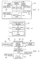
- FIGURE 1 shows one example of an optically linked network 100.
- the optically linked network 100 includes multiple electronic ingress edge routers 105, multiple optical core routers 110, multiple electronic egress edge routers 115, and multiple optical links 120.
- the optical links 120 connect the electronic ingress edge routers 105, the optical core routers 110, and the electronic egress edge routers 115 together.
- the electronic ingress edge routers 105 and electronic egress edge routers 115 serve as legacy interfaces between the optically linked network 100 and conventional electronic routers.
- the optical core routers 110 serve as packet switching devices. Each optical core router 110 examines every packet passing through it and routes the packets to their proper destination.
- each optical core router 110 examine and process each and every packet passing through it.
- the data packets normally have to pass through optical core router two to get to optical core router three. If eighty percent (80%) of the packets originating in optical core router one have a destination of optical core router three, then there is no need for the same eighty percent of the packets to be examined or processed in optical core router two.
- An optical crossconnect 210 can be placed above optical core router two to route the same eighty percent of the traffic around optical core router two. Routing eighty percent of the packet traffic which does not need to be processed by optical core router two around optical core router two effectively reduces the number of fibers which need to be active for processing packets.
- FIGURE 2 also shows a close up view 205 of how an optical crossconnect 210 and optical core router 110 currently work together to route traffic around the optical core router two.
- the crossconnect (OXC) 210 and optical core router 110 are two separate devices.
- Optical link 120 enters a multiplexor/demultiplexor 220 and is divided into multiple fiber lines entering both the optical crossconnect 210 and the optical core router 110. All packets which need not be processed in optical core router 110 can be routed through the crossconnect through fiber lines 225, multiplexed/demultiplexed at the multiplexor/demultiplexor 215 and transmitted on to optical core router three on optical link 120.
- FIGURE 3 shows an optical core router 110 having its own management software 305, switch controller 310, and optical switching matrix 315.
- a burst header 320 enters the optical core router 110 through control channel 325.
- the management software 305 electronically processes the mapping information within the burst header 320 and transmits that mapping information to the switch controller 310.
- the switch controller 310 then transmits the mapping information to the optical switching matrix 315.
- the mapping information directs the switch controller 310 to establish a switched optical path in the optical switching matrix 315 between any two ports on demand for a specific period of time to enable the passage of a burst payload 330 between the desired input and output ports.
- FIGURE 4 shows an optical packet switching apparatus 400 having an integrated optical crossconnect/optical core router 415.
- the integrated optical crossconnect/optical core router 415 is controlled by one management software program 405 and one optical switch control mechanism 410.
- the optical crossconnect/optical core router 415 use only one optical switching matrix 315.
- FIGURE 5 shows one example of a functional diagram for the optical packet switching apparatus 400 which integrates optical crossconnect and optical packet switching functionality in a single optical packet switching matrix.
- the optical packet switching apparatus 400 includes a network manager 505, a resource management mechanism 405, a port availability database 520, an optical switch control mechanism 410, and an optical switching matrix 525.
- the resource management mechanism 405 can either be a software computer program or a hardware device.
- the resource management mechanism 405 can function as an optical core router 110, a switch 515, or an optical crossconnect (OXC) 210.
- the resource management mechanism 405 When the resource management mechanism 405 is functioning as a router, it transmits detailed mapping information to the switch control mechanism 410 on how to map an optical path from an input to an output port in the optical switching matrix 525.
- the optical path allows a particular burst payload 330 to be switched through the optical switching matrix 525 to its proper destination.
- the mapping information also includes how long the optical path should remain open.
- the resource management mechanism 405 when the resource management mechanism 405 is functioning as a an optical core router 110, the optical path remains open only for the amount of time required to switch a particular burst payload 330 through the optical switching matrix 515.
- the resource management mechanism 405 can also function as an optical crossconnect 210.
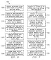
- FIGURE 6 shows a flow diagram 600 illustrating a set of steps that enable crossconnect functionality in an optical packet switching apparatus 400.
- the optical packet switching apparatus 400 can be any all optical packet switching apparatus or any fixed or variable length synchronous optical packet switching apparatus.
- a network manager 505 begins by transmitting a request to the resource management mechanism 405 for allocation of an output port with respect to a given input port in the optical packet switching matrix 525.
- the network manager 505 can either be a software program or a person controlling the optical network 100.
- the resource management mechanism 405 queries the port availability database 520 to determine the availability of the requested output port in step 610.
- the port availability database tracks which optical packet switching matrix inputs and outputs are currently being used, which input and output ports are being used as optical crossconnects, and which input and output ports are free. If the requested output port is available, then the port availability database 520 transmits mapping information back to the resource management mechanism 405 and the resource management mechanism 405 reserves the output port in step 615.
- the resource management mechanism 405 After reserving the output port, the resource management mechanism 405 then transmits the optical switching matrix input and output mapping information to the optical switch control mechanism 410 in step 620.
- the optical switch control mechanism 410 creates an optical path between the optical switching matrix input and output ports in step 625.
- the optical switch control mechanism 410 then informs the resource management mechanism 405 and the network manager 505 that the optical path has been established in step 630.
- the resource management mechanism 405 or the network manager 505 can optionally inform other network elements in the optical network system 100 that the optical path has been established in step 635.
- the port availability database 520 transmits that information to the resource management mechanism and the network manager.
- the network manager can then inquire on the availability of another output port.
- FIGURE 7 shows a flow diagram illustrating a set of steps that disable crossconnect functionality in an optical packet switching apparatus 400.
- a network manager 505 begins by transmitting a request to the resource management mechanism 405 to close an optical path from an input port to an output port within the optical packet switching matrix 525.
- the resource management mechanism 405 then transmits the closing request to the switch control mechanism 410 to free the input and output ports of the optical path in step 710.
- the switch control mechanism 410 then closes the optical path between the optical packet switching matrix input and output ports in step 715.
- the switch control mechanism 410 then informs the resource management mechanism 405 and the network manager 505 that the optical packet switching matrix input and output ports are free in step 720.
- the resource management mechanism 405 or network manager 505 updates the port availability database 520 that the input and output ports are now free in step 725. Finally, the resource management mechanism 405 or the network manager 505 can optionally inform other network elements in the optical network system 100 that the optical path has been disabled in step 730.
- a network manager begins by transmitting a request to a resource management mechanism for allocation for an output port with respect to an input port in an optical switching matrix.
- the resource management mechanism queries a port availability database to determine the availability of the requested output port. If an output port is available, the resource management mechanism then reserves the requested output port.
- the resource management mechanism transmits mapping information for an optical path between the input port and the reserved output port to an optical switch control mechanism.
- the optical switch control mechanism then creates the optical path between the said input port the reserved output port.
- the optical switch control mechanism then informs the resource management mechanism that the optical path is established.
Landscapes
- Engineering & Computer Science (AREA)
- Computer Networks & Wireless Communication (AREA)
- Data Exchanges In Wide-Area Networks (AREA)
- Optical Communication System (AREA)
- Use Of Switch Circuits For Exchanges And Methods Of Control Of Multiplex Exchanges (AREA)
Abstract
Description
- The present invention relates generally to optical network systems, and more particularly to a system and method for integrating optical crossconnect functionality in an optical packet switching apparatus.
- Data traffic over networks, particularly the internet, has increased dramatically over the past several years, and this trend will continue with the introduction of new services which require more bandwidth. Over time and technological advancements the bandwidth bottleneck kept shifting between the transmission and switching. Now transmission technology has advanced to a level that the routers, which essentially switch packets, have become bottlenecks. The advance of Wavelength Division Multiplexing (WDM) has enabled overcome this transmission bottleneck. The enlarged volume of internet traffic requires a network with high transmission capacity and high capacity routers capable of routing data packets at a very high rate. One option is to use all-optical routers.
- Advances in optical component technology had made it possible to make optical switching elements such as a Semiconductor Optical Amplifier (SOA) that would be electrically controlled to switch at nano-second response range. So a switching matrix made of a number of SOAs and controlled by routing protocols and a resource management software or hardware will enable all optical routers to act as a synchronous or asynchronous fixed or variable length packet switching apparatus.
- One approach called burst switching attempts to make the best use of optical switching and electronic/software router technologies. It becomes feasible to implement an all-optical packet switching apparatus using burst switching technique. It creates a burst switched network with conventional packet switching devices such as routers with a special function at the ingress and egress points (edge) of this burst switched network. The special function to be performed by the edge packet switching devices would be assembly of multiple packets into one payload and send it into the burst switching network as a burst. Similarly they would unassemble packets in an incoming burst payload and send them as conventional packets outside of the burst switched network. When it is in the process of assembling bursts into a payload it would already have sent a header to the appropriate all-optical packet switch through which all the packets assembled into the payload has to pass through. The header would contain information about the contents, the arrival port and the destination port(s), the length of the burst payload etc. The all-optical packet switching device would receive this header and process it electronically and keep the switching matrix ready for an interval of time to allow the corresponding payload that would follow later at a known time instance to switch over to the right exit port.
- Optical crossconnects on the other hand are not restricted to packets. They are devices that just make interconnections between an input port and output port to facilitate the establishment of light paths between devices connected to these two ports. They do not examine the packets that pass through them nor do they switch individual packets. Optical crossconnects are primarily used to establish steady optical paths between two circuit switching or packet switching devices. They also use a optical switching matrix to establish this connectivity. Currently, optical packet switching devices and optical crossconnects are two physically separate systems having separate switching hardware and software with possible interoperable ports for interconnection.
- The present invention provides an optical network that substantially eliminates or reduces disadvantages and problems associated with previously developed optical networks used for switching data.
- More specifically, the present invention provides a method for integrating optical crossconnect functionality in an optical packet switching apparatus. To integrate optical crossconnect functionality in an optical packet switching apparatus, a network manager begins by transmitting a request to a resource management mechanism for allocation for an output port with respect to an input port in an optical switching matrix. The resource management mechanism then queries a port availability database to determine the availability of the requested output port. If an output port is available, the resource management mechanism then reserves the requested output port. The resource management mechanism then transmits mapping information for an optical path between the input port and the reserved output port to an optical switch control mechanism. The optical switch control mechanism then creates the optical path between the said input port the reserved output port. Next, the optical switch control mechanism then informs the resource management mechanism that the optical path is established.
- The present invention provides an important technical advantage by providing a method for integrating optical crossconnect and packet switching functionality in a single optical packet switching apparatus, thus reducing the number of components and cost.
- The present invention provides another technical advantage by providing an optical packet switching apparatus with optical crossconnect function which works for any fixed length, variable length, synchronous, or asynchronous optical packet.
- For a more complete understanding of the present invention and the advantages thereof, reference is now made to the following description taken in conjunction with the accompanying drawings in which like reference numerals indicate like features and wherein:
- FIGURE 1 shows one example of an optically linked
network 100; - FIGURE 2 shows a prior art view illustrating the current method for providing optical crossconnect and optical packet switching functionality in an optically linked network;
- FIGURE 3 shows an optical core router having its
own management software,
switch controller 310, and optical switching matrix; - FIGURE 4 shows one example of an optical packet switching apparatus having integrated optical crossconnect and optical packet switching functionality;
- FIGURE 5 shows one example of a functional diagram for the optical packet switching apparatus;
- FIGURE 6 shows a flow diagram illustrating a set of steps that enable crossconnect functionality in an optical packet switching apparatus; and
- FIGURE 7 shows a flow diagram illustrating a set
of steps that disable crossconnect functionality in an
optical
packet switching apparatus 400. -
- Preferred embodiments of the present invention are illustrated in the FIGURES, like numerals being used to refer to like and corresponding parts of the various drawings.
- A network manager begins to integrate optical crossconnect functionality in an optical packet switching apparatus by transmitting a request to a resource management mechanism for allocation for an output port with respect to an input port in an optical switching matrix. The resource management mechanism then queries a port availability database to determine the availability of the requested output port. If an output port is available, the resource management mechanism then reserves the requested output port. The resource management mechanism then transmits mapping information for an optical path between the input port and the reserved output port to an optical switch control mechanism. The optical switch control mechanism then creates the optical path between the said input port the reserved output port. Finally, the optical switch control mechanism informs the resource management mechanism that the optical path is established. The reserved input and output ports are not available for the optical router part of the mechanism until the are made available to the router.
- FIGURE 1 shows one example of an optically linked
network 100. The optically linkednetwork 100 includes multiple electronicingress edge routers 105, multipleoptical core routers 110, multiple electronicegress edge routers 115, and multipleoptical links 120. Theoptical links 120 connect the electronicingress edge routers 105, theoptical core routers 110, and the electronicegress edge routers 115 together. The electronicingress edge routers 105 and electronicegress edge routers 115 serve as legacy interfaces between the optically linkednetwork 100 and conventional electronic routers. Theoptical core routers 110 serve as packet switching devices. Eachoptical core router 110 examines every packet passing through it and routes the packets to their proper destination. - In some cases, it is not necessary that each
optical core router 110 examine and process each and every packet passing through it. For example, as shown in FIGURE 2, the data packets normally have to pass through optical core router two to get to optical core router three. If eighty percent (80%) of the packets originating in optical core router one have a destination of optical core router three, then there is no need for the same eighty percent of the packets to be examined or processed in optical core router two. Anoptical crossconnect 210 can be placed above optical core router two to route the same eighty percent of the traffic around optical core router two. Routing eighty percent of the packet traffic which does not need to be processed by optical core router two around optical core router two effectively reduces the number of fibers which need to be active for processing packets. FIGURE 2 also shows a close upview 205 of how anoptical crossconnect 210 andoptical core router 110 currently work together to route traffic around the optical core router two. As shown in the close upview 205 of FIGURE 2, the crossconnect (OXC) 210 andoptical core router 110 are two separate devices.Optical link 120 enters a multiplexor/demultiplexor 220 and is divided into multiple fiber lines entering both theoptical crossconnect 210 and theoptical core router 110. All packets which need not be processed inoptical core router 110 can be routed through the crossconnect throughfiber lines 225, multiplexed/demultiplexed at the multiplexor/demultiplexor 215 and transmitted on to optical core router three onoptical link 120. - The current solution requires both an optical crossconnect and an optical core router to have their own switching matrix, management software, power source, and internal optical amplifiers. FIGURE 3 shows an
optical core router 110 having itsown management software 305,switch controller 310, andoptical switching matrix 315. Aburst header 320 enters theoptical core router 110 throughcontrol channel 325. Themanagement software 305 electronically processes the mapping information within theburst header 320 and transmits that mapping information to theswitch controller 310. Theswitch controller 310 then transmits the mapping information to theoptical switching matrix 315. The mapping information directs theswitch controller 310 to establish a switched optical path in theoptical switching matrix 315 between any two ports on demand for a specific period of time to enable the passage of aburst payload 330 between the desired input and output ports. - A better solution is have an optical packet switching apparatus which functions as an optical crossconnect and an optical router with only one optical switching matrix and one integrated management software program. This idea is illustrated in FIGURE 4. FIGURE 4 shows an optical
packet switching apparatus 400 having an integrated optical crossconnect/optical core router 415. The integrated optical crossconnect/optical core router 415 is controlled by onemanagement software program 405 and one opticalswitch control mechanism 410. Furthermore, the optical crossconnect/optical core router 415 use only oneoptical switching matrix 315. - FIGURE 5 shows one example of a functional diagram for the optical
packet switching apparatus 400 which integrates optical crossconnect and optical packet switching functionality in a single optical packet switching matrix. The opticalpacket switching apparatus 400 includes anetwork manager 505, aresource management mechanism 405, aport availability database 520, an opticalswitch control mechanism 410, and anoptical switching matrix 525. Theresource management mechanism 405 can either be a software computer program or a hardware device. Furthermore, theresource management mechanism 405 can function as anoptical core router 110, aswitch 515, or an optical crossconnect (OXC) 210. - When the
resource management mechanism 405 is functioning as a router, it transmits detailed mapping information to theswitch control mechanism 410 on how to map an optical path from an input to an output port in theoptical switching matrix 525. The optical path allows aparticular burst payload 330 to be switched through theoptical switching matrix 525 to its proper destination. The mapping information also includes how long the optical path should remain open. In most cases, when theresource management mechanism 405 is functioning as a anoptical core router 110, the optical path remains open only for the amount of time required to switch aparticular burst payload 330 through theoptical switching matrix 515. However, in situations where a large number of packets need not be processed and simply need to pass through a particularoptical core router 110, theresource management mechanism 405 can also function as anoptical crossconnect 210. - FIGURE 6 shows a flow diagram 600 illustrating a set of steps that enable crossconnect functionality in an optical
packet switching apparatus 400. The opticalpacket switching apparatus 400 can be any all optical packet switching apparatus or any fixed or variable length synchronous optical packet switching apparatus. Instep 605, anetwork manager 505 begins by transmitting a request to theresource management mechanism 405 for allocation of an output port with respect to a given input port in the opticalpacket switching matrix 525. Thenetwork manager 505 can either be a software program or a person controlling theoptical network 100. Theresource management mechanism 405 then queries theport availability database 520 to determine the availability of the requested output port instep 610. The port availability database tracks which optical packet switching matrix inputs and outputs are currently being used, which input and output ports are being used as optical crossconnects, and which input and output ports are free. If the requested output port is available, then theport availability database 520 transmits mapping information back to theresource management mechanism 405 and theresource management mechanism 405 reserves the output port instep 615. - After reserving the output port, the
resource management mechanism 405 then transmits the optical switching matrix input and output mapping information to the opticalswitch control mechanism 410 instep 620. Next, the opticalswitch control mechanism 410 creates an optical path between the optical switching matrix input and output ports instep 625. The opticalswitch control mechanism 410 then informs theresource management mechanism 405 and thenetwork manager 505 that the optical path has been established instep 630. Finally, theresource management mechanism 405 or thenetwork manager 505 can optionally inform other network elements in theoptical network system 100 that the optical path has been established instep 635. However, if the requested output port is not available, theport availability database 520 transmits that information to the resource management mechanism and the network manager. The network manager can then inquire on the availability of another output port. - FIGURE 7 shows a flow diagram illustrating a set of steps that disable crossconnect functionality in an optical
packet switching apparatus 400. Instep 705, anetwork manager 505 begins by transmitting a request to theresource management mechanism 405 to close an optical path from an input port to an output port within the opticalpacket switching matrix 525. Theresource management mechanism 405 then transmits the closing request to theswitch control mechanism 410 to free the input and output ports of the optical path instep 710. Theswitch control mechanism 410 then closes the optical path between the optical packet switching matrix input and output ports instep 715. Theswitch control mechanism 410 then informs theresource management mechanism 405 and thenetwork manager 505 that the optical packet switching matrix input and output ports are free instep 720. Next, theresource management mechanism 405 ornetwork manager 505 updates theport availability database 520 that the input and output ports are now free instep 725. Finally, theresource management mechanism 405 or thenetwork manager 505 can optionally inform other network elements in theoptical network system 100 that the optical path has been disabled instep 730. - In summary, to integrate optical crossconnect functionality in an optical packet switching apparatus, a network manager begins by transmitting a request to a resource management mechanism for allocation for an output port with respect to an input port in an optical switching matrix. The resource management mechanism then queries a port availability database to determine the availability of the requested output port. If an output port is available, the resource management mechanism then reserves the requested output port. The resource management mechanism then transmits mapping information for an optical path between the input port and the reserved output port to an optical switch control mechanism. The optical switch control mechanism then creates the optical path between the said input port the reserved output port. Next, the optical switch control mechanism then informs the resource management mechanism that the optical path is established.
- Although the present invention has been described in detail, it should be understood that various changes, substitutions and alterations can be made hereto without departing from the spirit and scope of the invention as described by the appended claims.
Claims (28)
- A method for integrating optical crossconnect functionality in an optical packet switching apparatus, comprising the steps of:requesting allocation for an output port with respect to an input port in an optical switching matrix;querying a port availability database to determine the availability of said requested output port;reserving said requested output port if available;transmitting mapping information for an optical path between said input port and said reserved output port to an optical switch control mechanism;creating said optical path between said input port and said reserved output port; andinforming a resource management mechanism that said optical path is established.
- The method of Claim 1, further comprising the steps of:informing a network manager that said requested output port is not available;informing said network manager that said optical path is established; andinforming a plurality of network elements in an optical network that said optical path has been established.
- The method of Claim 2, wherein said network manager requests allocation for said requested output port.
- The method of Claim 2, wherein said network manager is a software program controlling said optical network.
- The method of Claim 2, wherein said network manager is a person controlling said optical network.
- The method of Claim 1, wherein said resource management mechanism queries said port availability database to determine the availability of said requested output port.
- The method of Claim 1, wherein said resource management mechanism reserves said requested output port.
- The method of Claim 1, wherein said resource management mechanism transmits said mapping information to said optical switch control mechanism.
- The method of Claim 1, wherein said optical switch control mechanism creates said optical path between said input port and said reserved output port in said optical switching matrix.
- The method of Claim 1, wherein said optical switch control mechanism informs said resource management mechanism that said optical path has been established.
- The method of Claim 2, wherein said port availability database informs said network manager that said requested output port is not available.
- The method of Claim 2, wherein said resource management mechanism informs said plurality of network elements in said optical network that said optical path has been established.
- The method of Claim 2, wherein said network manager informs said plurality of network elements in said optical network that said optical path has been established.
- The method of Claim 1, wherein said resource management mechanism functions as an optical core router, a switch, or an optical crossconnect.
- The method of Claim 1, wherein said port availability database tracks said input and output ports of said optical switching matrix are reserved, and which said input and output ports of said optical switching matrix are free.
- The method of Claim 1, wherein said optical crossconnect functionality is integrated into any all optical, fixed or variable length, synchronous or asynchronous packet switching apparatus.
- A method for disabling optical crossconnect functionality from an optical packet switching apparatus, comprising the steps of:requesting a closing of an optical path from an input port to an output port within an optical switching matrix;transmitting said closing request to an optical switch control mechanism to disable said optical path; andclosing said optical path between said input port and said reserved output port in said optical switching matrix;informing a resource management mechanism that said optical path is closed and said input and reserved output ports are free.
- The method of Claim 17, further comprising the steps of:updating a port availability database with information that said input port and said output ports are free;informing said network manager that said input port and said reserved output ports are free; andinforming a plurality of network elements in an optical network that said input port and reserved output ports are free.
- The method of Claim 17, wherein said network manager requests a closing of said optical path from said input port to said output port within said optical switching matrix.
- The method of Claim 18, wherein said network manager is a software program controlling said optical network.
- The method of Claim 18, wherein said network manager is a person controlling said optical network.
- The method of Claim 17, wherein said resource management mechanism transmits said closing request to said optical switch control mechanism to disable said optical path.
- The method of Claim 17, wherein said optical switch control mechanism closes said optical path between said input port and said reserved output port in said optical switching matrix.
- The method of Claim 17, wherein said optical switch control mechanism informs said resource management mechanism or said network manager that said optical path is closed and said input and output ports are free.
- The method of Claim 18, wherein said resource management mechanism or said network manager updates said port availability database that said input and output ports are free.
- The method of Claim 18, wherein said resource management mechanism or said network manager informs said plurality of network elements in said optical network that said optical path is closed.
- The method of Claim 17, wherein said resource management mechanism functions as an optical core router, a switch, or an optical crossconnect.
- The method of Claim 18, wherein said port availability database tracks said input and output ports of said optical switching matrix are reserved, and which said input and output ports of said optical switching matrix are free.
Applications Claiming Priority (2)
| Application Number | Priority Date | Filing Date | Title |
|---|---|---|---|
| US519066 | 2000-03-03 | ||
| US09/519,066 US6763192B1 (en) | 2000-03-03 | 2000-03-03 | Integration of all-optical crossconnect functionality in an optical packet switching apparatus |
Publications (3)
| Publication Number | Publication Date |
|---|---|
| EP1130942A2 true EP1130942A2 (en) | 2001-09-05 |
| EP1130942A3 EP1130942A3 (en) | 2008-01-02 |
| EP1130942B1 EP1130942B1 (en) | 2011-08-17 |
Family
ID=24066646
Family Applications (1)
| Application Number | Title | Priority Date | Filing Date |
|---|---|---|---|
| EP01440053A Expired - Lifetime EP1130942B1 (en) | 2000-03-03 | 2001-03-02 | Integration of all-optical crossconnect functionality in an optical packet switching apparatus |
Country Status (4)
| Country | Link |
|---|---|
| US (1) | US6763192B1 (en) |
| EP (1) | EP1130942B1 (en) |
| JP (1) | JP4806130B2 (en) |
| CA (1) | CA2339893A1 (en) |
Cited By (1)
| Publication number | Priority date | Publication date | Assignee | Title |
|---|---|---|---|---|
| WO2003056758A1 (en) * | 2001-12-31 | 2003-07-10 | Eci Telecom Ltd. | Technique of determining connectivity solutions for network elements |
Families Citing this family (21)
| Publication number | Priority date | Publication date | Assignee | Title |
|---|---|---|---|---|
| US6721508B1 (en) | 1998-12-14 | 2004-04-13 | Tellabs Operations Inc. | Optical line terminal arrangement, apparatus and methods |
| US6665495B1 (en) * | 2000-10-27 | 2003-12-16 | Yotta Networks, Inc. | Non-blocking, scalable optical router architecture and method for routing optical traffic |
| US7170862B1 (en) * | 2001-07-31 | 2007-01-30 | Cisco Technology, Inc. | Partitioning a network element into multiple virtual network elements |
| US7002960B1 (en) * | 2001-10-30 | 2006-02-21 | At&T Corp. | Traffic matrix computation for packet networks |
| US7743139B1 (en) | 2001-10-30 | 2010-06-22 | At&T Intellectual Property Ii, L.P. | Method of provisioning a packet network for handling incoming traffic demands |
| CA2410064C (en) * | 2001-11-02 | 2007-12-04 | Nippon Telegraph And Telephone Corporation | Optical dynamic burst switch |
| CA2410143C (en) * | 2001-11-02 | 2010-02-02 | Nippon Telegraph And Telephone Corporation | Optical dynamic burst switch |
| US7126963B2 (en) * | 2002-05-23 | 2006-10-24 | International Business Machines Corporation | Apparatus, method and computer program to reserve resources in communications system |
| US20030223405A1 (en) * | 2002-05-31 | 2003-12-04 | El-Bawab Tarek S. | WDM metropolitan access network architecture based on hybrid switching |
| CN100365995C (en) * | 2005-04-04 | 2008-01-30 | 华为技术有限公司 | A method for opening an Ethernet service |
| US7706685B2 (en) * | 2005-09-20 | 2010-04-27 | Lockheed Martin Corporation | Data communication network using optical power averaged multiplexing |
| US8249451B2 (en) * | 2007-08-16 | 2012-08-21 | Futurewei Technologies, Inc. | Methods for characterizing optical switches and multiplexers/demultiplexers |
| WO2009074840A2 (en) * | 2007-12-10 | 2009-06-18 | George Madathilparambil George | Separately transmitting part of protocol information |
| US9848209B2 (en) | 2008-04-02 | 2017-12-19 | Microsoft Technology Licensing, Llc | Adaptive error detection for MPEG-2 error concealment |
| US9788018B2 (en) | 2008-06-30 | 2017-10-10 | Microsoft Technology Licensing, Llc | Error concealment techniques in video decoding |
| US9131241B2 (en) * | 2008-11-25 | 2015-09-08 | Microsoft Technology Licensing, Llc | Adjusting hardware acceleration for video playback based on error detection |
| US8340510B2 (en) | 2009-07-17 | 2012-12-25 | Microsoft Corporation | Implementing channel start and file seek for decoder |
| US9054828B2 (en) * | 2011-10-14 | 2015-06-09 | Glimmerglass Networks, Inc. | Method and system for managing optical distribution network |
| WO2014014846A2 (en) * | 2012-07-15 | 2014-01-23 | Packet Photonics, Inc. | Control systems for optical devices and subassemblies |
| US9660755B2 (en) * | 2012-10-18 | 2017-05-23 | Ciena Corporation | Automated node level fibre audit |
| PL445152A1 (en) * | 2023-06-07 | 2024-12-09 | Politechnika Śląska | Method of preparing lightweight construction aggregate from aerated concrete waste and lightweight construction aggregate obtained by this method |
Citations (2)
| Publication number | Priority date | Publication date | Assignee | Title |
|---|---|---|---|---|
| US4873681A (en) | 1988-01-26 | 1989-10-10 | Bell Communications Research, Inc. | Hybrid optical and electronic packet switch |
| WO1998031184A1 (en) | 1997-01-07 | 1998-07-16 | Tellium, Inc. | Hybrid wavelength-interchanging cross-connect |
Family Cites Families (16)
| Publication number | Priority date | Publication date | Assignee | Title |
|---|---|---|---|---|
| EP0547836B1 (en) | 1991-12-16 | 2001-12-19 | AT&T Corp. | Optical packet switch |
| US5416769A (en) | 1993-07-13 | 1995-05-16 | At&T Corp. | Controlled-feedback packet switching system |
| US5486943A (en) | 1993-07-14 | 1996-01-23 | Nippon Telegraph And Telephone Corp. | Photonic frequency division multiplexed FIFO buffer |
| JP3186376B2 (en) * | 1993-10-25 | 2001-07-11 | 日本電気株式会社 | Network recovery control method |
| FR2725528B1 (en) | 1994-10-11 | 1996-11-22 | Alcatel Nv | WAVELENGTH-SELECTIVE OPTICAL DELAY LINE |
| FR2726726A1 (en) | 1994-11-04 | 1996-05-10 | Guillemot Christian | SWITCH SYSTEM FOR OPTICAL PACKETS |
| FR2729040B1 (en) | 1994-12-29 | 1997-01-31 | Alcatel Nv | PHOTON SWITCHING MATRIX |
| US5781537A (en) * | 1995-07-07 | 1998-07-14 | International Business Machines Corporation | Setting up, taking down and maintaining connections in a communications network |
| JPH09121217A (en) * | 1995-08-23 | 1997-05-06 | Fujitsu Ltd | Burst transfer method |
| US5771320A (en) | 1996-04-30 | 1998-06-23 | Wavefront Research, Inc. | Optical switching and routing system |
| JPH10242989A (en) * | 1997-02-28 | 1998-09-11 | Nec Corp | Photoelectric composite type network node control system |
| CA2236285C (en) * | 1997-05-08 | 2003-09-16 | Hitachi Ltd. | Network and switching node in which resource can be reserved |
| JPH10308776A (en) * | 1997-05-08 | 1998-11-17 | Hitachi Ltd | Network resource reservation method |
| JPH11122258A (en) * | 1997-10-15 | 1999-04-30 | Fujitsu Ltd | Optical wavelength routing method and optical wavelength routing system |
| US6563793B1 (en) * | 1998-11-25 | 2003-05-13 | Enron Warpspeed Services, Inc. | Method and apparatus for providing guaranteed quality/class of service within and across networks using existing reservation protocols and frame formats |
| US6671256B1 (en) * | 2000-02-03 | 2003-12-30 | Alcatel | Data channel reservation in optical burst-switched networks |
-
2000
- 2000-03-03 US US09/519,066 patent/US6763192B1/en not_active Expired - Lifetime
-
2001
- 2001-02-27 JP JP2001052852A patent/JP4806130B2/en not_active Expired - Fee Related
- 2001-03-02 EP EP01440053A patent/EP1130942B1/en not_active Expired - Lifetime
- 2001-03-02 CA CA002339893A patent/CA2339893A1/en not_active Abandoned
Patent Citations (2)
| Publication number | Priority date | Publication date | Assignee | Title |
|---|---|---|---|---|
| US4873681A (en) | 1988-01-26 | 1989-10-10 | Bell Communications Research, Inc. | Hybrid optical and electronic packet switch |
| WO1998031184A1 (en) | 1997-01-07 | 1998-07-16 | Tellium, Inc. | Hybrid wavelength-interchanging cross-connect |
Non-Patent Citations (2)
| Title |
|---|
| D. K. HUNTER ET AL.: "WASPNET: A Wavelength Switched Packet Network", IEEE COMMUNICATIONS MAGAZINE, vol. 37, no. 3, March 1999 (1999-03-01), pages 120 - 129 |
| MICHAEL S. BORELLA ET AL.: "Optical Components for WDM Lightwave Networks", PROCEEDINGS OF THE IEEE, vol. 85, no. 8, August 1997 (1997-08-01) |
Cited By (3)
| Publication number | Priority date | Publication date | Assignee | Title |
|---|---|---|---|---|
| WO2003056758A1 (en) * | 2001-12-31 | 2003-07-10 | Eci Telecom Ltd. | Technique of determining connectivity solutions for network elements |
| CN100409618C (en) * | 2001-12-31 | 2008-08-06 | Eci电信公司 | Techniques to determine connectivity solutions for network elements |
| US8327021B2 (en) | 2001-12-31 | 2012-12-04 | Eci Telecom Ltd | Technique of determining connectivity solutions for network elements |
Also Published As
| Publication number | Publication date |
|---|---|
| EP1130942A3 (en) | 2008-01-02 |
| CA2339893A1 (en) | 2001-09-03 |
| US6763192B1 (en) | 2004-07-13 |
| JP2001320421A (en) | 2001-11-16 |
| JP4806130B2 (en) | 2011-11-02 |
| EP1130942B1 (en) | 2011-08-17 |
Similar Documents
| Publication | Publication Date | Title |
|---|---|---|
| US6763192B1 (en) | Integration of all-optical crossconnect functionality in an optical packet switching apparatus | |
| US6671256B1 (en) | Data channel reservation in optical burst-switched networks | |
| JP4380895B2 (en) | Optical switch and protocol used there | |
| US20040208547A1 (en) | QoS based protection of mesh-based intelligent optical networks | |
| KR20030040207A (en) | Optical transport networks | |
| CA2343576A1 (en) | Supervisory control plane over wavelength routed networks | |
| US8223779B2 (en) | Systems and methods for parallel multi-core control plane processing | |
| RU2299529C2 (en) | Device and method for commutation of a set of signals with usage of multi-step protocol processing | |
| CA2439726C (en) | Connection-oriented communication network and method of operating | |
| JP2004505527A (en) | Communications system | |
| US20040103209A1 (en) | System and method for controlling switch devices supporting generalized multi-protocol label switching | |
| DE60213926T2 (en) | Advanced signaling system for switching and control in optical integrated networks | |
| EP1045611B1 (en) | Method of supporting shortcuts in the network layer | |
| US6985443B2 (en) | Method and apparatus for alleviating traffic congestion in a computer network | |
| US20030016671A1 (en) | Wavelength division multiplexed network with frame switching | |
| EP1289207A2 (en) | A method of deriving a route through a network | |
| CA2299038C (en) | Mpls application to optical cross connect using wavelength as a label | |
| Yasui et al. | Internetworking based on wavelength assignment photonic switching system (WAPS) | |
| Sohraby et al. | Resource management in an integrated optical network | |
| Silvent Aparicio | UCLP in flow state router platforms | |
| Kumar | Hybrid Nodal Architecture for Traffic Grooming in WDM Networks |
Legal Events
| Date | Code | Title | Description |
|---|---|---|---|
| PUAI | Public reference made under article 153(3) epc to a published international application that has entered the european phase |
Free format text: ORIGINAL CODE: 0009012 |
|
| AK | Designated contracting states |
Kind code of ref document: A2 Designated state(s): AT BE CH CY DE DK ES FI FR GB GR IE IT LI LU MC NL PT SE TR |
|
| AX | Request for extension of the european patent |
Free format text: AL;LT;LV;MK;RO;SI |
|
| RAP1 | Party data changed (applicant data changed or rights of an application transferred) |
Owner name: ALCATEL LUCENT |
|
| PUAL | Search report despatched |
Free format text: ORIGINAL CODE: 0009013 |
|
| AK | Designated contracting states |
Kind code of ref document: A3 Designated state(s): AT BE CH CY DE DK ES FI FR GB GR IE IT LI LU MC NL PT SE TR |
|
| AX | Request for extension of the european patent |
Extension state: AL LT LV MK RO SI |
|
| 17P | Request for examination filed |
Effective date: 20080528 |
|
| 17Q | First examination report despatched |
Effective date: 20080619 |
|
| AKX | Designation fees paid |
Designated state(s): AT BE CH CY DE DK ES FI FR GB GR IE IT LI LU MC NL PT SE TR |
|
| GRAP | Despatch of communication of intention to grant a patent |
Free format text: ORIGINAL CODE: EPIDOSNIGR1 |
|
| RBV | Designated contracting states (corrected) |
Designated state(s): DE ES FR GB IT |
|
| GRAS | Grant fee paid |
Free format text: ORIGINAL CODE: EPIDOSNIGR3 |
|
| GRAA | (expected) grant |
Free format text: ORIGINAL CODE: 0009210 |
|
| AK | Designated contracting states |
Kind code of ref document: B1 Designated state(s): DE ES FR GB IT |
|
| REG | Reference to a national code |
Ref country code: GB Ref legal event code: FG4D |
|
| REG | Reference to a national code |
Ref country code: DE Ref legal event code: R096 Ref document number: 60145154 Country of ref document: DE Effective date: 20111020 |
|
| RAP2 | Party data changed (patent owner data changed or rights of a patent transferred) |
Owner name: ALCATEL LUCENT |
|
| PG25 | Lapsed in a contracting state [announced via postgrant information from national office to epo] |
Ref country code: IT Free format text: LAPSE BECAUSE OF FAILURE TO SUBMIT A TRANSLATION OF THE DESCRIPTION OR TO PAY THE FEE WITHIN THE PRESCRIBED TIME-LIMIT Effective date: 20110817 |
|
| PLBE | No opposition filed within time limit |
Free format text: ORIGINAL CODE: 0009261 |
|
| STAA | Information on the status of an ep patent application or granted ep patent |
Free format text: STATUS: NO OPPOSITION FILED WITHIN TIME LIMIT |
|
| 26N | No opposition filed |
Effective date: 20120521 |
|
| REG | Reference to a national code |
Ref country code: DE Ref legal event code: R097 Ref document number: 60145154 Country of ref document: DE Effective date: 20120521 |
|
| PG25 | Lapsed in a contracting state [announced via postgrant information from national office to epo] |
Ref country code: ES Free format text: LAPSE BECAUSE OF FAILURE TO SUBMIT A TRANSLATION OF THE DESCRIPTION OR TO PAY THE FEE WITHIN THE PRESCRIBED TIME-LIMIT Effective date: 20111128 |
|
| REG | Reference to a national code |
Ref country code: GB Ref legal event code: 732E Free format text: REGISTERED BETWEEN 20130926 AND 20131002 |
|
| REG | Reference to a national code |
Ref country code: FR Ref legal event code: GC Effective date: 20131018 |
|
| REG | Reference to a national code |
Ref country code: FR Ref legal event code: RG Effective date: 20141016 |
|
| REG | Reference to a national code |
Ref country code: FR Ref legal event code: PLFP Year of fee payment: 15 |
|
| REG | Reference to a national code |
Ref country code: FR Ref legal event code: PLFP Year of fee payment: 16 |
|
| REG | Reference to a national code |
Ref country code: FR Ref legal event code: PLFP Year of fee payment: 17 |
|
| REG | Reference to a national code |
Ref country code: FR Ref legal event code: PLFP Year of fee payment: 18 |
|
| PGFP | Annual fee paid to national office [announced via postgrant information from national office to epo] |
Ref country code: FR Payment date: 20180329 Year of fee payment: 18 |
|
| REG | Reference to a national code |
Ref country code: GB Ref legal event code: 732E Free format text: REGISTERED BETWEEN 20190429 AND 20190502 |
|
| REG | Reference to a national code |
Ref country code: DE Ref legal event code: R082 Ref document number: 60145154 Country of ref document: DE Representative=s name: MENZIETTI WETZEL, DE Ref country code: DE Ref legal event code: R081 Ref document number: 60145154 Country of ref document: DE Owner name: PROVENANCE ASSET GROUP LLC, PITTSFORD, US Free format text: FORMER OWNER: ALCATEL LUCENT, PARIS, FR |
|
| PG25 | Lapsed in a contracting state [announced via postgrant information from national office to epo] |
Ref country code: FR Free format text: LAPSE BECAUSE OF NON-PAYMENT OF DUE FEES Effective date: 20190331 |
|
| PGFP | Annual fee paid to national office [announced via postgrant information from national office to epo] |
Ref country code: DE Payment date: 20200320 Year of fee payment: 20 Ref country code: GB Payment date: 20200323 Year of fee payment: 20 |
|
| REG | Reference to a national code |
Ref country code: DE Ref legal event code: R071 Ref document number: 60145154 Country of ref document: DE |
|
| REG | Reference to a national code |
Ref country code: GB Ref legal event code: PE20 Expiry date: 20210301 |
|
| PG25 | Lapsed in a contracting state [announced via postgrant information from national office to epo] |
Ref country code: GB Free format text: LAPSE BECAUSE OF EXPIRATION OF PROTECTION Effective date: 20210301 |