EP1130906B1 - Pointing device for digital camera display - Google Patents
Pointing device for digital camera display Download PDFInfo
- Publication number
- EP1130906B1 EP1130906B1 EP00125790A EP00125790A EP1130906B1 EP 1130906 B1 EP1130906 B1 EP 1130906B1 EP 00125790 A EP00125790 A EP 00125790A EP 00125790 A EP00125790 A EP 00125790A EP 1130906 B1 EP1130906 B1 EP 1130906B1
- Authority
- EP
- European Patent Office
- Prior art keywords
- camera
- display
- motion
- image
- cursor
- Prior art date
- Legal status (The legal status is an assumption and is not a legal conclusion. Google has not performed a legal analysis and makes no representation as to the accuracy of the status listed.)
- Expired - Lifetime
Links
Images


Classifications
-
- G—PHYSICS
- G06—COMPUTING; CALCULATING OR COUNTING
- G06F—ELECTRIC DIGITAL DATA PROCESSING
- G06F3/00—Input arrangements for transferring data to be processed into a form capable of being handled by the computer; Output arrangements for transferring data from processing unit to output unit, e.g. interface arrangements
- G06F3/01—Input arrangements or combined input and output arrangements for interaction between user and computer
- G06F3/03—Arrangements for converting the position or the displacement of a member into a coded form
- G06F3/0304—Detection arrangements using opto-electronic means
-
- G—PHYSICS
- G06—COMPUTING; CALCULATING OR COUNTING
- G06F—ELECTRIC DIGITAL DATA PROCESSING
- G06F1/00—Details not covered by groups G06F3/00 - G06F13/00 and G06F21/00
- G06F1/16—Constructional details or arrangements
- G06F1/1613—Constructional details or arrangements for portable computers
- G06F1/1626—Constructional details or arrangements for portable computers with a single-body enclosure integrating a flat display, e.g. Personal Digital Assistants [PDAs]
-
- G—PHYSICS
- G06—COMPUTING; CALCULATING OR COUNTING
- G06F—ELECTRIC DIGITAL DATA PROCESSING
- G06F1/00—Details not covered by groups G06F3/00 - G06F13/00 and G06F21/00
- G06F1/16—Constructional details or arrangements
- G06F1/1613—Constructional details or arrangements for portable computers
- G06F1/1633—Constructional details or arrangements of portable computers not specific to the type of enclosures covered by groups G06F1/1615 - G06F1/1626
- G06F1/1684—Constructional details or arrangements related to integrated I/O peripherals not covered by groups G06F1/1635 - G06F1/1675
- G06F1/1686—Constructional details or arrangements related to integrated I/O peripherals not covered by groups G06F1/1635 - G06F1/1675 the I/O peripheral being an integrated camera
-
- H—ELECTRICITY
- H04—ELECTRIC COMMUNICATION TECHNIQUE
- H04N—PICTORIAL COMMUNICATION, e.g. TELEVISION
- H04N23/00—Cameras or camera modules comprising electronic image sensors; Control thereof
- H04N23/60—Control of cameras or camera modules
- H04N23/63—Control of cameras or camera modules by using electronic viewfinders
- H04N23/631—Graphical user interfaces [GUI] specially adapted for controlling image capture or setting capture parameters
- H04N23/632—Graphical user interfaces [GUI] specially adapted for controlling image capture or setting capture parameters for displaying or modifying preview images prior to image capturing, e.g. variety of image resolutions or capturing parameters
-
- H—ELECTRICITY
- H04—ELECTRIC COMMUNICATION TECHNIQUE
- H04N—PICTORIAL COMMUNICATION, e.g. TELEVISION
- H04N23/00—Cameras or camera modules comprising electronic image sensors; Control thereof
- H04N23/60—Control of cameras or camera modules
- H04N23/63—Control of cameras or camera modules by using electronic viewfinders
- H04N23/633—Control of cameras or camera modules by using electronic viewfinders for displaying additional information relating to control or operation of the camera
- H04N23/635—Region indicators; Field of view indicators
-
- G—PHYSICS
- G06—COMPUTING; CALCULATING OR COUNTING
- G06F—ELECTRIC DIGITAL DATA PROCESSING
- G06F2200/00—Indexing scheme relating to G06F1/04 - G06F1/32
- G06F2200/16—Indexing scheme relating to G06F1/16 - G06F1/18
- G06F2200/163—Indexing scheme relating to constructional details of the computer
- G06F2200/1637—Sensing arrangement for detection of housing movement or orientation, e.g. for controlling scrolling or cursor movement on the display of an handheld computer
Definitions
- the present invention relates to digital cameras and, more particularly, to a pointing device-based graphical user interface that uses the camera display.
- Digital cameras have not generally used pointing devices to interact with the interface presented on the display. Typically, they use a set of push buttons to step through menus and to select images from memory for display and deletion. New digital cameras may rely on micro display devices, instead of the now more common panel display. To view a micro display, the user needs to hold the display close to his or her eye and view the display through an eyepiece. This arrangement makes the interface controls more difficult to use, because the user will not be able to see the controls while viewing the display.
- JP 07131684 A relates to an image pickup device, in which a title selection screen is displayed with the push of a title selection key.
- the title selection screen includes four title screens reduced in a matrix shape, and a cursor is put on one of these title screens, i.e., the upper left screen, for example.
- a housing of a camcorder is panned or titled in the desired direction where a cursor is shifted.
- the shift direction of the cursor is detected by a shift direction detecting circuit and a microcomputer, and the cursor is shifted in the housing shift direction within the title selection screen.
- WO 99/32960 discloses a hand-held display device for use with an electronic device to display a complete or a determined part of a screen image, there are included control circuits, a display screen and control buttons connected to said control circuits. Further, a gyroscope is incorporated in said display device and connected to said control circuits, whereby said display device is responsive to movements in the space for displaying said screen image in different magnifications, and/or in different parts. A fixed pointer is arranged on the display screen for controlling applications shown on the display screen.
- the invention provides for a process according to claim 1 and a camara according to claim 3.
- a process and apparatus is described to improve a digital camera user interface and increase ease of use and functionality of a digital camera by quickly, accurately and robustly permitting cursor control and designation in a digital camera display.
- a digital camera is used as a pointing device such as a mouse or trackball.
- the motion of the camera is detected, and the motion of the camera is used to position graphic elements on the camera's own display.
- the camera's motion can be detected with sensors, such as gyroscopes, or the camera itself can be used as a motion sensor.
- sensors such as gyroscopes
- One application of this involves using the camera as a computer mouse, or like a gun-sight, to select images from a sheet of low-resolution (“thumbnail”) images.
- the motion of the camera is tracked, and the user aims at the desired image from a sheet of thumbnail images.
- the thumbnails appear to be fixed relative to the world because the camera can continuously reposition them in the display based upon the motion of the camera. The user can then select a thumbnail in an intuitive manner by simply pointing the camera at the desired thumbnail.
- the interface can be used to select regions of greater extent than can be viewed in the viewer or to virtually review images.
- the invention described here allows a digital camera to be used as a pointing device such as a mouse or trackball.
- the motion of the camera is detected, and the motion of the camera is used to position graphic elements on the camera's own display.
- the camera's motion can be detected with sensors, such as gyroscopes, or the camera itself can be used as a motion sensor.
- sensors such as gyroscopes
- One application of this involves using the camera as a computer mouse, or like a gun-sight, to select images from a sheet of low-resolution (“thumbnail”) images.
- the motion of the camera is tracked, and the user aims at the desired image from a sheet of thumbnail images. This application is illustrated in greater detail below in connection with figures 3a, 3b and 4 .
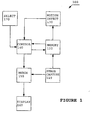
- Figure 1 is a block diagram illustrating a pointing device-based graphical user interface system for a digital camera display according to the present invention.
- image capture unit 110 In digital camera 100, an image is captured by image capture unit 110.
- the image capture unit 110 can be selected from among the many such devices known in the art.
- image capture unit 110 will be either a CCD or CMOS imaging device, as is commonly used for image sensing in modern digital cameras.
- motion detection unit 130 uses the changes between subsequent images to calculate an amount and direction of motion for camera 100.
- motion detection unit 130 uses the changes between subsequent images to calculate an amount and direction of motion for camera 100.
- One such method is described in United States Patent 5,808,678, Yuji Sakaegi , entitled “Method and Apparatus for Designing a Position on a View Finder Based on Motion Detection", which issued September 15, 1998.
- Another such method is described in United States Patent 5,786,804, Gary B. Gordon , entitled “Method and System for Tracking Attitude", which issued July 28, 1998.
- a first image capture unit can be used for capture of the digital picture taken by the camera and separate image capture unit can be used for the motion detection.
- motion detection is not performed optically by comparing subsequent images.
- non-optical motion sensing techniques that are also well known in the art are used.
- One such method would be to use gyroscopes as described, for example, in United States patent 5,825,350, Case, Jr. et al. , "Electronic Pointing Apparatus and Method", which issued October 20, 1998.
- control unit 140 causes merge unit 150 to combine the motion detection information with the captured image and then this merged information is displayed on display 160.
- a cursor and a set of icons such as thumbnail images, could be merged with the series of images being captured by capture unit 110. Motion of the camera 100 would be detected and cause the thumbnail images to move within the display.
- selection unit 170 It is preferred that selection unit 170 be a switch on the camera 100.
- other forms of selection such as voice command detection, are known in the art and could be employed alternatively.
- suitable displays 160 include viewfinder micro displays such as are manufactured by the MicroDisplay Corporation, San Pablo, California, USA, or by Displaytech, of Longmont, Colorado, USA. Although it is preferred that display 160 be a view finder micro display, there are many forms of suitable displays such as panel displays that are well known in the art.
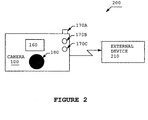
- FIG. 2 is a diagram illustrating a digital imaging system having a pointing device-based graphical user interface camera according to the present invention.
- camera 100 is shown coupled to external device 210.
- the coupling can be accomplished using wire cable or fiber optic links.
- the coupling can also be accomplished using a wireless link such as infrared or radio links.
- External device 210 can include any of the many known external devices that are commonly associated with digital cameras such as a computer, external memory, modem, or printer. It is to be understood, however, that digital camera 100 need not be linked to external device 210 for the present invention to be practiced.
- camera 100 has a display 160 and three selection buttons 170A, 170B and 170C.
- image capture unit 180 is shown in figure 2 as being shaded because the image capture unit is generally located on the side of the camera opposite to the side having the display 160.
- selection button 170A is used to operate an optical or electronic zoom.
- Buttons 170B and 170C are used together in an application-specific manner.
- button 170C can be used to enter a particular mode, such as thumbnail image selection. In the thumbnail image selection mode, button 170B can then be used to select a particular thumbnail image when the camera motion causes the target thumbnail icon to be moved under the cursor.
- buttons makes it easy to use camera 100 as a gun-sight-like pointing device within a graphical user interface.
- Digital cameras have not generally used pointing devices to interact with the interface presented on the display.
- they use a set of push buttons to step through menus and to select images from memory for display and deletion.
- To view a micro display the user needs to hold the display close to his or her eye and view the display through an eyepiece. This arrangement makes the interface controls more difficult to use, because the user will not be able to see the controls while viewing the display.
- the present invention allows the user to interact with the information display in a way similar to the computer mouse.
- the entire body of the camera is moved, and the movement of the camera is recorded.
- the motion information can then be used to position a cursor, or to position graphic elements.
- graphic elements can be positioned so they stay fixed relative to the world as the user moves the camera.
- thumbnailnail a grid of low-resolution images.
- the thumbnail is selected by pressing buttons that move a cursor across the thumbnails until the desired picture is under the cursor.
- a computer within the camera can continuously reposition the thumbnails so they appear to be fixed relative to the world. The user can then select a thumbnail by simply pointing the camera at the desired thumbnail.
- the position of the camera is tracked by optical flow.
- the camera records a sequence of images.
- the motion of the camera can be estimated. Determining the motion of the camera by comparing sequential images taken with the camera is well described in the literature, and this approach has the advantage of not requiring any additional hardware.
- Alternative implementations use sensors such as gyroscopes, tilt sensors, compasses, or a GPS receiver to measure the position of the camera. These solutions may be more robust, but may also be more expensive to implement.
- Figures 3a and 3b illustrate use of the camera as a pointing device to select thumbnail images according to an embodiment of the present invention.
- a sheet of thumbnail images is shown superimposed on a view through the camera.
- the cross hair is a cursor, and for one embodiment, the cursor is always fixed relative to the camera, e.g., the cross hair cursor is fixed in the center of the view.
- the sheet of thumbnail images is fixed relative to the world by using motion tracking. That is, the computer constantly repositions the sheet as the camera moves, so the sheet seems to be fixed in position relative to the objects seen through the camera.
- the cursor moves relative to the world and to the world-fixed thumbnails. This allows the user to select an image by simply pointing the camera at the desired image.
- the camera itself is used as the only pointing device. No other mouse, joystick or other device need be used to move the cursor.
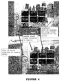
- Figure 4 is a diagram illustrating how the thumbnail images of Figures 3a and 3b are made to appear to be motionless relative to objects of the scene.
- Motion tracking software tracks the motion of image features in the scene. For example, the image of the computer monitor on the desk moved down and slightly right between frame 1 and frame 2. The sheet of thumbnails is moved by the same amount, and in the same direction, as the features in the scene. The sheet thus appears to be motionless relative to the objects in the scene (such as the computer monitor).
- thumbnails appear fixed relative to the world, the user can use the camera like a gun-sight.
- the cross hairs stay fixed relative to the camera, and the sheet of thumbnails stays fixed relative to the world, so the user can place the cross hairs on the desired thumbnail by simply aiming the camera.
- This feature provides a very simple to use and intuitive user interface.
- the viewfinder display may be a micro display that is viewed directly through some optics. Such a display has inherit advantages over a panel display, because it is typically brighter, higher resolution, has more colors, subtends a larger viewing angle, and requires less power. In one viewing mode, the operator of the camera can see the display at the same time as the scene.
- the display can be partially transparent, be optically mixed with the world by means of a beamsplitter, or digitally mixed with an image captured with the camera.
- the direct view of the scene is closed off, perhaps by means of a shutter. In this mode only the images on the display can be seen.
- the motion tracking keeps track of the camera's angular position in the world. As previously described, this can be done by tracking motion using the camera's light sensors, or it could be done with other instruments such as a compass, a gyroscope, a GPS sensor, or the like.
- the camera may be used to select positions or regions of the scene.
- the operator simply points the camera at objects or locations in the scene, and then uses a button or the like to indicate the selection. These regions can then be used to assist in the capture or processing of the image.
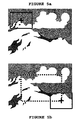
- Figures 5a and 5b illustrate use of the camera as a pointing device to select a portion of the scene.
- a rectangular region that is larger than the viewfinder of the camera can be selected by marking two opposite corners of the region.
- the selected rectangle is the dotted rectangle of figure 5b .
- the viewfinder is illustrated by the solid rectangle, and the cross-shaped cursor is used to select the first corner of the region in figure 5a , and the second, diagonal corner of the region in figure 5b .
- alternative shaped areas can be designated.
- two points could be specified to define a center and radius to designate a circular region, or N points could be chosen to specify an N-sided polygonal region.
- the region can be used for several purposes. It can delimit the boundaries of a region to be captured using multiple tiled images. It can be a region that is supposed to receive special processing, such as reduced image compression to preserve important details. It can also be used to change the zoom, so the camera can capture the framed region without any waste due to cropping.
- Selected locations can be fixed in space by tracking the camera's movement.
- moving selected targets can be tracked by means such as motion tracking. For example, a soccer player's face could be selected. Motion tracking would then track the face, and the focus could automatically be adjusted to keep this face in focus.
- Important scene locations that would aid in image capture can also be marked.
- the light source can be marked, and this information can greatly aid color correction or other image processing.
- the light source need not be located within the image to be photographed.
- the photographer can collect information for image processing by pointing the camera at the light source (or sources), either before or after capturing the image.
- the subject can be marked for auto-focus. Areas of the view can also be marked as triggers, where image motion in a trigger area will make the camera take a picture. For example, a tripod-mounted camera could be set to take a picture if motion is detected crossing the finish line of a racetrack.
- a viewfinder display that has look-through capability can display information that is usually presented on a small status-display. It can show the state of the flash, the amount of storage remaining, the degree of compression, and the like. If the user requires more information, the cursor can easily be moved over the status display to select a more detailed display of information. The information is easier to access from the viewfinder display, because it can be seen while the picture is being framed.
- the heads-up display can show the user the region or locations that have been selected.
- Figure 7 is a diagram illustrating use of heads-up data during guided swipe of a panoramic scene
- the camera can show the operator the selected region (the dashed rectangle), the area of the selected region that had already been captured (slightly darkened), and instructions on which way to point the camera to capture the unrecorded parts of the region (the left arrow).
- Figure 8 is a diagram illustrating tracking during virtual review of the panoramic scene.
- the user can view the panorama by looking into the viewfinder. Moving the camera will cause the panorama (the dashed rectangle) to move in the opposite direction in the camera, thus giving the impression that a large scene is being viewed through the window of the viewfinder (the solid rectangle).
- the operator will feel immersed in the panoramic scene.
- images that have more pixels than the micro display can show can be displayed. The operator simply moves the camera to view different parts of the image.
- FIG. 9 is a diagram illustrating image manipulation.
- the cursor can be used to adjust the contrast, brightness or hue of the selected image by dragging the slider for the appropriate icon.
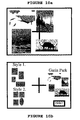
- Figures 10a and 10b illustrate use of the camera as a pointing device to select thumbnail images for high resolution page layout.
- the cursor is used to select thumbnail images in Figure 10a .
- the cursor is then used in figure 10b to select a page layout style and to cause the resulting image to be sent to a printer for printing.
- One advantage to performing these operations on the camera instead of after downloading the images to the computer is that the processing can be done before image compression. Some operations can also reduce the size of the image, which will thereby reduce the storage requirements for the image. For example, regions that were discarded when an image was cropped would not need to be stored on the camera. Further, this can eliminate the need for an external computer altogether.
- the images can be sent directly to the printer or other external device.
- a second image could be captured at a location that provides a good stereoscopic pair to the first image.
- the camera could also be used as a stereoscopic display device if it had two viewfinder displays. Alternatively, if the camera had two capture devices, stereoscopic images could be captured more easily, and stereoscopic panoramas could be captured. These panoramas could be reviewed with stereoscopic viewfinders in the virtual mode previously described.
- Game elements could be superimposed on the view of the scene, and motion tracking of the camera could be used to position the elements so they stay fixed relative to the scene.
- a computer graphic image of a ball could be launched from the camera. It could then be made to appear as if the ball had hit an object in the scene. The place where the ball had hit could be marked with further graphics.
- this information can be used to automatically record where and when the picture was taken.
- Any information on the angular position of the camera, the time of day, and the geographic location of the camera can also be used for color correcting the image. For example, if the picture were taken at night, the camera would not use color correction for daylight. Or, if it is known that the camera was facing north at 3 pm at a certain location, the position of the sun could be determined, and some useful characteristics of the sunlight could be estimated which would allow improved image processing.
Landscapes
- Engineering & Computer Science (AREA)
- Theoretical Computer Science (AREA)
- Human Computer Interaction (AREA)
- General Engineering & Computer Science (AREA)
- Computer Hardware Design (AREA)
- Physics & Mathematics (AREA)
- General Physics & Mathematics (AREA)
- Signal Processing (AREA)
- Multimedia (AREA)
- Studio Devices (AREA)
- Position Input By Displaying (AREA)
- User Interface Of Digital Computer (AREA)
- Viewfinders (AREA)
- Details Of Cameras Including Film Mechanisms (AREA)
- Cameras In General (AREA)
- Indication In Cameras, And Counting Of Exposures (AREA)
Description
- The present invention relates to digital cameras and, more particularly, to a pointing device-based graphical user interface that uses the camera display.
- Digital cameras have not generally used pointing devices to interact with the interface presented on the display. Typically, they use a set of push buttons to step through menus and to select images from memory for display and deletion. New digital cameras may rely on micro display devices, instead of the now more common panel display. To view a micro display, the user needs to hold the display close to his or her eye and view the display through an eyepiece. This arrangement makes the interface controls more difficult to use, because the user will not be able to see the controls while viewing the display.
- United States Patent
5,808,678, Yuji Sakaegi , entitled "Method and Apparatus for Designing a Position on a View Finder Based on Motion Detection", which issued September 15, 1998, describes the use of a switch, trackball, joystick or camera-motion controlled cursor to interact with the interface presented on a digital camera display. In the case of the switch, trackball or joystick, it is awkward to designate locations or icons when looking through the camera veiwfinder because the user must hold the camera while manipulating the controls. In the latter case, the motion of the camera is used to move the cursor about the viewfinder interface and select icons therein. This interface is also awkward to use, however, because the motion causes the cursor to wander around the viewing area in an unintuitive way. -
JP 07131684 A -
WO 99/32960 - Thus, it can be seen that modern user interface techniques impose ease of use and functionality limits upon digital cameras, and hinder the use of these cameras in many applications.
- Therefore, there is an unresolved need for an improved user interface technique that can increase digital camera ease of use and functionality by quickly, accurately and robustly permitting cursor control and designation in a digital camera display.
- The invention provides for a process according to
claim 1 and a camara according to claim 3. - A process and apparatus is described to improve a digital camera user interface and increase ease of use and functionality of a digital camera by quickly, accurately and robustly permitting cursor control and designation in a digital camera display.
- A digital camera is used as a pointing device such as a mouse or trackball. The motion of the camera is detected, and the motion of the camera is used to position graphic elements on the camera's own display. The camera's motion can be detected with sensors, such as gyroscopes, or the camera itself can be used as a motion sensor. One application of this involves using the camera as a computer mouse, or like a gun-sight, to select images from a sheet of low-resolution ("thumbnail") images. The motion of the camera is tracked, and the user aims at the desired image from a sheet of thumbnail images. The thumbnails appear to be fixed relative to the world because the camera can continuously reposition them in the display based upon the motion of the camera. The user can then select a thumbnail in an intuitive manner by simply pointing the camera at the desired thumbnail.
- For alternative embodiments; which do not form part of the invention, but represents background art that is useful for understanding the invention the interface can be used to select regions of greater extent than can be viewed in the viewer or to virtually review images.
- The invention will be readily understood by the following detailed description in conjunction with the accompanying drawings, wherein like reference numerals designate like structural elements, and in which:
-
Figure 1 is a block diagram illustrating a pointing device-based graphical user interface system for a digital camera display according to the present invention; -
Figure 2 is a diagram illustrating a digital imaging system having a pointing device-based graphical user interface camera according to the present invention; -
Figures 3a and 3b illustrate use of the camera as a pointing device to select thumbnail images according to an embodiment of the present invention; -
Figure 4 is a diagram illustrating how the thumbnail images ofFigures 3a and 3b are made to appear to be motionless relative to objects of the scene; -
Figures 5a and 5b illustrate use of the camera as a pointing device to select a portion of the scene larger than the viewfinder according to an embodiment of the present invention, which does not form part of the invention, but represents background out that is useful for understanding the invention; -
Figure 6 is a diagram illustrating heads-up display of status information according to an embodiment of the present invention, which does not form part of the invention, but represents background out that is useful for understanding the invention; -
Figure 7 is a diagram illustrating use of heads-up data during a guided swipe of a panoramic scene according to an embodiment of the present invention, which does not form part of the invention, but represents background out that is useful for understanding the invention; -
Figure 8 is a diagram illustrating tracking during virtual review of the panoramic scene according to an embodiment of the present invention, which does not form part of the invention, but represents background out that is useful for understanding the invention; -
Figure 9 is a diagram illustrating image manipulation according to an embodiment of the present invention, which does not form part of the invention, but represents background out that is useful for understanding the invention; and -
Figures 10a and 10b illustrate use of the camera as a pointing device to select thumbnail images for high resolution page layout according to an embodiment of the present invention, which does not form part of the invention, but represents background out that is useful for understanding the invention. - Embodiments of the invention are discussed below with reference to
Figures 1-4 . Those skilled in the art will readily appreciate that the detailed description given herein with respect to these figures is for explanatory purposes, however, because the invention extends beyond these limited embodiments. - The invention described here allows a digital camera to be used as a pointing device such as a mouse or trackball. The motion of the camera is detected, and the motion of the camera is used to position graphic elements on the camera's own display. The camera's motion can be detected with sensors, such as gyroscopes, or the camera itself can be used as a motion sensor. One application of this involves using the camera as a computer mouse, or like a gun-sight, to select images from a sheet of low-resolution ("thumbnail") images. The motion of the camera is tracked, and the user aims at the desired image from a sheet of thumbnail images. This application is illustrated in greater detail below in connection with
figures 3a, 3b and4 . -
Figure 1 is a block diagram illustrating a pointing device-based graphical user interface system for a digital camera display according to the present invention. Indigital camera 100, an image is captured byimage capture unit 110. Theimage capture unit 110 can be selected from among the many such devices known in the art. Preferably,image capture unit 110 will be either a CCD or CMOS imaging device, as is commonly used for image sensing in modern digital cameras. - One or more of a series of images captured by
image capture unit 110 will be stored at least temporarily inmemory 120. For one embodiment of the present invention,motion detection unit 130 uses the changes between subsequent images to calculate an amount and direction of motion forcamera 100. There are many techniques known in the art for calculation of motion based upon changes in captured images. One such method is described in United States Patent5,808,678, Yuji Sakaegi , entitled "Method and Apparatus for Designing a Position on a View Finder Based on Motion Detection", which issued September 15, 1998. Another such method is described in United States Patent5,786,804, Gary B. Gordon , entitled "Method and System for Tracking Attitude", which issued July 28, 1998. - Note that, although the system of
Figure 1 teaches the use of oneimage capture unit 110, for an alternative embodiment, a first image capture unit can be used for capture of the digital picture taken by the camera and separate image capture unit can be used for the motion detection. - Also note that, for another embodiment of the present invention, motion detection is not performed optically by comparing subsequent images. Instead, for these embodiments, non-optical motion sensing techniques that are also well known in the art are used. One such method would be to use gyroscopes as described, for example, in United States patent
5,825,350, Case, Jr. et al. , "Electronic Pointing Apparatus and Method", which issued October 20, 1998. - As will be described below in greater detail,
control unit 140 causes mergeunit 150 to combine the motion detection information with the captured image and then this merged information is displayed ondisplay 160. For example, a cursor and a set of icons, such as thumbnail images, could be merged with the series of images being captured bycapture unit 110. Motion of thecamera 100 would be detected and cause the thumbnail images to move within the display. When the desired icon moves under the cursor, the user could select this target icon by usingselection unit 170. It is preferred thatselection unit 170 be a switch on thecamera 100. However, other forms of selection, such as voice command detection, are known in the art and could be employed alternatively. - Examples of
suitable displays 160 include viewfinder micro displays such as are manufactured by the MicroDisplay Corporation, San Pablo, California, USA, or by Displaytech, of Longmont, Colorado, USA. Although it is preferred thatdisplay 160 be a view finder micro display, there are many forms of suitable displays such as panel displays that are well known in the art. -
Figure 2 is a diagram illustrating a digital imaging system having a pointing device-based graphical user interface camera according to the present invention. Infigure 2 ,camera 100 is shown coupled toexternal device 210. The coupling can be accomplished using wire cable or fiber optic links. The coupling can also be accomplished using a wireless link such as infrared or radio links.External device 210 can include any of the many known external devices that are commonly associated with digital cameras such as a computer, external memory, modem, or printer. It is to be understood, however, thatdigital camera 100 need not be linked toexternal device 210 for the present invention to be practiced. - In
figure 2 it can be seen that for this embodiment,camera 100 has adisplay 160 and threeselection buttons image capture unit 180 is shown infigure 2 as being shaded because the image capture unit is generally located on the side of the camera opposite to the side having thedisplay 160. - For this embodiment, three selection buttons, 170A, 170B and 170C, are shown. For this example,
selection button 170A is used to operate an optical or electronic zoom.Buttons button 170C can be used to enter a particular mode, such as thumbnail image selection. In the thumbnail image selection mode,button 170B can then be used to select a particular thumbnail image when the camera motion causes the target thumbnail icon to be moved under the cursor. - Note that this arrangement of buttons makes it easy to use
camera 100 as a gun-sight-like pointing device within a graphical user interface. Digital cameras have not generally used pointing devices to interact with the interface presented on the display. Typically, they use a set of push buttons to step through menus and to select images from memory for display and deletion. To view a micro display, the user needs to hold the display close to his or her eye and view the display through an eyepiece. This arrangement makes the interface controls more difficult to use, because the user will not be able to see the controls while viewing the display. - The present invention allows the user to interact with the information display in a way similar to the computer mouse. For one embodiment of the present invention, the entire body of the camera is moved, and the movement of the camera is recorded. The motion information can then be used to position a cursor, or to position graphic elements. For example, graphic elements can be positioned so they stay fixed relative to the world as the user moves the camera.
- With most digital still cameras, the user can load a previously captured image to the display by selecting it from a grid of low-resolution ("thumbnail") images. The thumbnail is selected by pressing buttons that move a cursor across the thumbnails until the desired picture is under the cursor. With the new method, the user can look into a micro display and will be presented with the thumbnails. A computer within the camera can continuously reposition the thumbnails so they appear to be fixed relative to the world. The user can then select a thumbnail by simply pointing the camera at the desired thumbnail.
- For one embodiment of the present implementation, the position of the camera is tracked by optical flow. The camera records a sequence of images. By comparing the images with each other, the motion of the camera can be estimated. Determining the motion of the camera by comparing sequential images taken with the camera is well described in the literature, and this approach has the advantage of not requiring any additional hardware. Alternative implementations use sensors such as gyroscopes, tilt sensors, compasses, or a GPS receiver to measure the position of the camera. These solutions may be more robust, but may also be more expensive to implement.
-
Figures 3a and 3b illustrate use of the camera as a pointing device to select thumbnail images according to an embodiment of the present invention. Infigure 3a , a sheet of thumbnail images is shown superimposed on a view through the camera. The cross hair is a cursor, and for one embodiment, the cursor is always fixed relative to the camera, e.g., the cross hair cursor is fixed in the center of the view. The sheet of thumbnail images is fixed relative to the world by using motion tracking. That is, the computer constantly repositions the sheet as the camera moves, so the sheet seems to be fixed in position relative to the objects seen through the camera. As shown infigure 3b , when the user moves the camera, the cursor moves relative to the world and to the world-fixed thumbnails. This allows the user to select an image by simply pointing the camera at the desired image. The camera itself is used as the only pointing device. No other mouse, joystick or other device need be used to move the cursor. -
Figure 4 is a diagram illustrating how the thumbnail images ofFigures 3a and 3b are made to appear to be motionless relative to objects of the scene. Motion tracking software tracks the motion of image features in the scene. For example, the image of the computer monitor on the desk moved down and slightly right betweenframe 1 andframe 2. The sheet of thumbnails is moved by the same amount, and in the same direction, as the features in the scene. The sheet thus appears to be motionless relative to the objects in the scene (such as the computer monitor). - Because the thumbnails appear fixed relative to the world, the user can use the camera like a gun-sight. The cross hairs stay fixed relative to the camera, and the sheet of thumbnails stays fixed relative to the world, so the user can place the cross hairs on the desired thumbnail by simply aiming the camera. This feature provides a very simple to use and intuitive user interface.
- The viewfinder display may be a micro display that is viewed directly through some optics. Such a display has inherit advantages over a panel display, because it is typically brighter, higher resolution, has more colors, subtends a larger viewing angle, and requires less power. In one viewing mode, the operator of the camera can see the display at the same time as the scene. The display can be partially transparent, be optically mixed with the world by means of a beamsplitter, or digitally mixed with an image captured with the camera.
- In a second alternative mode, the direct view of the scene is closed off, perhaps by means of a shutter. In this mode only the images on the display can be seen. There could also be other alternative modes where part of the scene is masked off, and in these regions only the display can be seen. For example, the operator could view a mixture of an optical view of the scene with graphics in the top half of the display, and only graphical status information against a black background in the bottom half of the display. The masking can even be done with an electronic element, where the display information can be made to appear as an opaque overlay to the optical view of the scene.
- The motion tracking keeps track of the camera's angular position in the world. As previously described, this can be done by tracking motion using the camera's light sensors, or it could be done with other instruments such as a compass, a gyroscope, a GPS sensor, or the like.
- The camera may be used to select positions or regions of the scene. The operator simply points the camera at objects or locations in the scene, and then uses a button or the like to indicate the selection. These regions can then be used to assist in the capture or processing of the image.
-
Figures 5a and 5b illustrate use of the camera as a pointing device to select a portion of the scene. For example, a rectangular region that is larger than the viewfinder of the camera can be selected by marking two opposite corners of the region. In this example, the selected rectangle is the dotted rectangle offigure 5b . The viewfinder is illustrated by the solid rectangle, and the cross-shaped cursor is used to select the first corner of the region infigure 5a , and the second, diagonal corner of the region infigure 5b . Note that alternative shaped areas can be designated. For example, two points could be specified to define a center and radius to designate a circular region, or N points could be chosen to specify an N-sided polygonal region. - Regardless of its shape, the region can be used for several purposes. It can delimit the boundaries of a region to be captured using multiple tiled images. It can be a region that is supposed to receive special processing, such as reduced image compression to preserve important details. It can also be used to change the zoom, so the camera can capture the framed region without any waste due to cropping.
- Selected locations can be fixed in space by tracking the camera's movement. Alternatively, moving selected targets can be tracked by means such as motion tracking. For example, a soccer player's face could be selected. Motion tracking would then track the face, and the focus could automatically be adjusted to keep this face in focus.
- Important scene locations that would aid in image capture can also be marked. For example, the light source can be marked, and this information can greatly aid color correction or other image processing. Note that the light source need not be located within the image to be photographed. The photographer can collect information for image processing by pointing the camera at the light source (or sources), either before or after capturing the image. The subject can be marked for auto-focus. Areas of the view can also be marked as triggers, where image motion in a trigger area will make the camera take a picture. For example, a tripod-mounted camera could be set to take a picture if motion is detected crossing the finish line of a racetrack.
- As shown in
figure 6 , a viewfinder display that has look-through capability can display information that is usually presented on a small status-display. It can show the state of the flash, the amount of storage remaining, the degree of compression, and the like. If the user requires more information, the cursor can easily be moved over the status display to select a more detailed display of information. The information is easier to access from the viewfinder display, because it can be seen while the picture is being framed. When using the virtual selection described above, the heads-up display can show the user the region or locations that have been selected.Figure 7 is a diagram illustrating use of heads-up data during guided swipe of a panoramic scene In this example of capturing a large region with multiple tiled images, the camera can show the operator the selected region (the dashed rectangle), the area of the selected region that had already been captured (slightly darkened), and instructions on which way to point the camera to capture the unrecorded parts of the region (the left arrow). - With motion tracking and a viewfinder display, the operator can be presented with a virtual panorama.
Figure 8 is a diagram illustrating tracking during virtual review of the panoramic scene. After capture and tiling to form an oversized image, such as a panorama, the user can view the panorama by looking into the viewfinder. Moving the camera will cause the panorama (the dashed rectangle) to move in the opposite direction in the camera, thus giving the impression that a large scene is being viewed through the window of the viewfinder (the solid rectangle). The operator will feel immersed in the panoramic scene. Alternatively, images that have more pixels than the micro display can show can be displayed. The operator simply moves the camera to view different parts of the image. - The combination of a high-resolution colorful viewfinder display with a camera permits the camera to be used for image manipulations such as cropping, color correction and page layout.
Figure 9 is a diagram illustrating image manipulation. In this example, the cursor can be used to adjust the contrast, brightness or hue of the selected image by dragging the slider for the appropriate icon. -
Figures 10a and 10b illustrate use of the camera as a pointing device to select thumbnail images for high resolution page layout. The cursor is used to select thumbnail images inFigure 10a . The cursor is then used infigure 10b to select a page layout style and to cause the resulting image to be sent to a printer for printing. - One advantage to performing these operations on the camera instead of after downloading the images to the computer is that the processing can be done before image compression. Some operations can also reduce the size of the image, which will thereby reduce the storage requirements for the image. For example, regions that were discarded when an image was cropped would not need to be stored on the camera. Further, this can eliminate the need for an external computer altogether. The images can be sent directly to the printer or other external device.
- If the position of the camera is very precisely known, a higher resolution image can be synthesized from several images taken with slightly different locations.
- Also, by tracking the camera's position and possibly even guiding the operator to the correct position, a second image could be captured at a location that provides a good stereoscopic pair to the first image. The camera could also be used as a stereoscopic display device if it had two viewfinder displays. Alternatively, if the camera had two capture devices, stereoscopic images could be captured more easily, and stereoscopic panoramas could be captured. These panoramas could be reviewed with stereoscopic viewfinders in the virtual mode previously described.
- By having computer graphics combined with an optical view of the scene, new types of games would be possible. Game elements could be superimposed on the view of the scene, and motion tracking of the camera could be used to position the elements so they stay fixed relative to the scene. For example, a computer graphic image of a ball could be launched from the camera. It could then be made to appear as if the ball had hit an object in the scene. The place where the ball had hit could be marked with further graphics.
- If the full position of the camera in multiple dimensions is collected, by means of GPS for example, this information can be used to automatically record where and when the picture was taken. Any information on the angular position of the camera, the time of day, and the geographic location of the camera can also be used for color correcting the image. For example, if the picture were taken at night, the camera would not use color correction for daylight. Or, if it is known that the camera was facing north at 3 pm at a certain location, the position of the sun could be determined, and some useful characteristics of the sunlight could be estimated which would allow improved image processing.
- The many features and advantages of the invention are apparent from the written description and thus it is intended by the appended claims to cover all such features and advantages of the invention. Further, because numerous modifications and changes will readily occur to those skilled in the art, it is not desired to limit the invention to the exact construction and operation as illustrated and described. Hence, all suitable modifications and equivalents may be resorted to as falling within the scope of the invention, as defined by the appended claims.
Claims (3)
- A process for a camera (100) having a display (160), the process comprising the steps of:displaying a cursor and a plurality of icons on the display (160) superimposed on a view through the camera representing an image scene;moving the camera (100);sensing motion (130) of the camera (100);based on the motion, repositioning the icons in the display (160) until the cursor is on a target icon of the plurality of icons; andselecting (170) the target icon,wherein the icons are repositioned to appear to be fixed in space with regard to the image scene being viewed in the display (160) and the cursor is displayed at a fixed position on the display.
- The process as set forth in claim 1, wherein the icons are repositioned in a direction opposite, and of corresponding magnitude, to the motion of the camera (100).
- A camera (100) having a display (160), the camera (100) comprising:a motion sensor to sense motion (130) of the camera (100);circuitry to display a cursor and a plurality of icons on the display (160) superimposed on a view through the camera representing an image scene, based on the motion, the circuitry repositioning the icons in the display (160) until the cursor is on a target icon of the plurality of icons, wherein the icons are repositioned to appear to be fixed in space with regard to the image scene being viewed in the display (160); anda selector (170) to select the target icon and the cursor is displayedat a fixed position on the display.
Applications Claiming Priority (2)
| Application Number | Priority Date | Filing Date | Title |
|---|---|---|---|
| US09/484,667 US7187412B1 (en) | 2000-01-18 | 2000-01-18 | Pointing device for digital camera display |
| US484667 | 2000-01-18 |
Publications (3)
| Publication Number | Publication Date |
|---|---|
| EP1130906A2 EP1130906A2 (en) | 2001-09-05 |
| EP1130906A3 EP1130906A3 (en) | 2001-12-19 |
| EP1130906B1 true EP1130906B1 (en) | 2011-09-28 |
Family
ID=23925099
Family Applications (1)
| Application Number | Title | Priority Date | Filing Date |
|---|---|---|---|
| EP00125790A Expired - Lifetime EP1130906B1 (en) | 2000-01-18 | 2000-11-24 | Pointing device for digital camera display |
Country Status (3)
| Country | Link |
|---|---|
| US (2) | US7187412B1 (en) |
| EP (1) | EP1130906B1 (en) |
| JP (1) | JP4928670B2 (en) |
Cited By (1)
| Publication number | Priority date | Publication date | Assignee | Title |
|---|---|---|---|---|
| CN101158886B (en) * | 2002-11-20 | 2012-05-16 | 皇家飞利浦电子股份有限公司 | User interface system based on pointing device |
Families Citing this family (69)
| Publication number | Priority date | Publication date | Assignee | Title |
|---|---|---|---|---|
| GB2377147A (en) * | 2001-06-27 | 2002-12-31 | Nokia Corp | A virtual reality user interface |
| JP5037765B2 (en) * | 2001-09-07 | 2012-10-03 | 株式会社トプコン | Operator guidance system |
| US6765555B2 (en) * | 2001-11-07 | 2004-07-20 | Omnivision Technologies, Inc. | Passive optical mouse using image sensor with optional dual mode capability |
| WO2003056505A1 (en) | 2001-12-21 | 2003-07-10 | British Telecommunications Public Limited Company | Device and method for calculating a location on a display |
| JP4346859B2 (en) * | 2002-03-27 | 2009-10-21 | 富士フイルム株式会社 | Image pickup apparatus, image display method and program in image pickup apparatus |
| DE10233608A1 (en) * | 2002-07-24 | 2004-02-12 | Siemens Ag | Input device for a terminal |
| CN100452868C (en) * | 2003-01-17 | 2009-01-14 | 日本电信电话株式会社 | Remote video display method, video acquisition device, method thereof, and program thereof |
| WO2004066632A1 (en) * | 2003-01-17 | 2004-08-05 | Nippon Telegraph And Telephone Corporation | Remote video display method, video acquisition device, method thereof, and program thereof |
| US20060146009A1 (en) * | 2003-01-22 | 2006-07-06 | Hanno Syrbe | Image control |
| KR100469727B1 (en) * | 2003-03-07 | 2005-02-02 | 삼성전자주식회사 | Communication terminal and method capable of displaying face image of user at the middle part of screen |
| JP4864295B2 (en) * | 2003-06-02 | 2012-02-01 | 富士フイルム株式会社 | Image display system, image display apparatus, and program |
| US8989516B2 (en) * | 2007-09-18 | 2015-03-24 | Fotonation Limited | Image processing method and apparatus |
| US8264576B2 (en) | 2007-03-05 | 2012-09-11 | DigitalOptics Corporation Europe Limited | RGBW sensor array |
| US20130010138A1 (en) * | 2003-06-26 | 2013-01-10 | Petronel Bigioi | Digital Camera with an Image Processor |
| US8698924B2 (en) | 2007-03-05 | 2014-04-15 | DigitalOptics Corporation Europe Limited | Tone mapping for low-light video frame enhancement |
| US8948468B2 (en) | 2003-06-26 | 2015-02-03 | Fotonation Limited | Modification of viewing parameters for digital images using face detection information |
| FR2859800B1 (en) * | 2003-09-12 | 2008-07-04 | Wavecom | PORTABLE ELECTRONIC DEVICE WITH MAN-MACHINE INTERFACE TAKING ACCOUNT OF DEVICE MOVEMENTS, CORRESPONDING METHOD AND COMPUTER PROGRAM |
| US20050122405A1 (en) * | 2003-12-09 | 2005-06-09 | Voss James S. | Digital cameras and methods using GPS/time-based and/or location data to provide scene selection, and dynamic illumination and exposure adjustment |
| DK1776688T3 (en) * | 2004-03-19 | 2013-06-10 | Arbitron Inc | Collect data regarding the use of a publication |
| FR2868902B1 (en) * | 2004-04-07 | 2006-09-22 | Eastman Kodak Co | VIEWING METHOD AND APPARATUS FOR SIMULATING THE OPTICAL EFFECT OF A LENTICULAR NETWORK TEST |
| EP1600848A1 (en) * | 2004-05-28 | 2005-11-30 | Siemens Aktiengesellschaft | A method and program for selecting an input symbol, and a device for the same |
| US7372597B2 (en) * | 2004-07-27 | 2008-05-13 | Eastman Kodak Company | Tonescales for geographically localized digital rendition of people |
| WO2006018775A2 (en) * | 2004-08-12 | 2006-02-23 | Philips Intellectual Property & Standards Gmbh | Method and system for controlling a display |
| FI20045300A (en) * | 2004-08-17 | 2006-02-18 | Nokia Corp | Electronic device and procedure for controlling the functions of the electronic device and software product for implementing the procedure |
| US8184155B2 (en) * | 2007-07-11 | 2012-05-22 | Ricoh Co. Ltd. | Recognition and tracking using invisible junctions |
| FR2876470B1 (en) * | 2004-10-12 | 2006-12-22 | Eastman Kodak Co | DISPLAY CONTROL METHOD USING PORTABLE IMAGE SENSOR EQUIPMENT |
| FR2879064B1 (en) * | 2004-12-03 | 2007-06-01 | Eastman Kodak Co | METHOD FOR BROADCASTING MULTIMEDIA DATA TO EQUIPMENT PROVIDED WITH AN IMAGE SENSOR |
| EP1849123A2 (en) | 2005-01-07 | 2007-10-31 | GestureTek, Inc. | Optical flow based tilt sensor |
| WO2006074310A2 (en) | 2005-01-07 | 2006-07-13 | Gesturetek, Inc. | Creating 3d images of objects by illuminating with infrared patterns |
| ATE551675T1 (en) | 2005-01-21 | 2012-04-15 | Qualcomm Inc | MOTION BASED TRACKING |
| JP2006237713A (en) * | 2005-02-22 | 2006-09-07 | Casio Comput Co Ltd | Image pickup device, mark preparing method, and program |
| KR100687737B1 (en) * | 2005-03-19 | 2007-02-27 | 한국전자통신연구원 | Apparatus and method for a virtual mouse based on two-hands gesture |
| JP4104605B2 (en) * | 2005-03-29 | 2008-06-18 | 株式会社東芝 | Image processing device |
| JP2006303651A (en) * | 2005-04-15 | 2006-11-02 | Nokia Corp | Electronic device |
| CN103257684B (en) * | 2005-05-17 | 2017-06-09 | 高通股份有限公司 | The signal output method and device of orientation-sensitive |
| EP1915664A2 (en) * | 2005-08-11 | 2008-04-30 | Koninklijke Philips Electronics N.V. | Method of determining the motion of a pointing device |
| JP5319867B2 (en) * | 2005-09-28 | 2013-10-16 | Kddi株式会社 | Information terminal equipment |
| DE102005048336A1 (en) * | 2005-10-10 | 2007-04-12 | Robert Bosch Gmbh | Method and system for assisting the driver of a motor vehicle in recognizing the surroundings of the motor vehicle |
| US7697827B2 (en) | 2005-10-17 | 2010-04-13 | Konicek Jeffrey C | User-friendlier interfaces for a camera |
| GB2431804B (en) * | 2005-10-31 | 2011-04-13 | Hewlett Packard Development Co | Image capture device and method of capturing an image |
| JP2007159095A (en) * | 2005-11-14 | 2007-06-21 | Olympus Imaging Corp | Imaging apparatus |
| US20080018669A1 (en) * | 2006-07-18 | 2008-01-24 | General Electric Company | method and system for integrated image zoom and montage |
| KR101315308B1 (en) * | 2006-08-24 | 2013-10-04 | 삼성전자주식회사 | Method for controlling digital photographing apparatus, and digital photographing apparatus adopting the method |
| JP4725526B2 (en) * | 2006-08-28 | 2011-07-13 | ソニー株式会社 | Information processing apparatus, imaging apparatus, information processing system, apparatus control method, and program |
| US20080063615A1 (en) * | 2006-09-12 | 2008-03-13 | Macdonald John Gavin | Color changing skin sealant |
| US20080063389A1 (en) * | 2006-09-13 | 2008-03-13 | General Instrument Corporation | Tracking a Focus Point by a Remote Camera |
| JP2010515170A (en) | 2006-12-29 | 2010-05-06 | ジェスチャー テック,インコーポレイテッド | Manipulating virtual objects using an enhanced interactive system |
| JP2008299620A (en) * | 2007-05-31 | 2008-12-11 | Toshiba Corp | Pointing device and pointing method |
| JP2008305108A (en) * | 2007-06-06 | 2008-12-18 | Sharp Corp | Handwriting input device, control method thereof, handwriting input control program, and recording medium with the program recorded thereon |
| US8122356B2 (en) * | 2007-10-03 | 2012-02-21 | Eastman Kodak Company | Method for image animation using image value rules |
| JP5053158B2 (en) * | 2008-04-18 | 2012-10-17 | 富士フイルム株式会社 | Display device, operation control method, and program |
| JP5117288B2 (en) * | 2008-06-12 | 2013-01-16 | オリンパスイメージング株式会社 | Imaging device and setting method of imaging device |
| JP5200816B2 (en) * | 2008-09-24 | 2013-06-05 | カシオ計算機株式会社 | Imaging device, image processing method of imaging device, and image processing program |
| US20100088637A1 (en) * | 2008-10-07 | 2010-04-08 | Himax Media Solutions, Inc. | Display Control Device and Display Control Method |
| US20100138797A1 (en) * | 2008-12-01 | 2010-06-03 | Sony Ericsson Mobile Communications Ab | Portable electronic device with split vision content sharing control and method |
| US8121472B2 (en) * | 2009-09-10 | 2012-02-21 | Babak Forutanpour | Signal measurements employed to affect photographic parameters |
| US20110273369A1 (en) * | 2010-05-10 | 2011-11-10 | Canon Kabushiki Kaisha | Adjustment of imaging property in view-dependent rendering |
| US20110273731A1 (en) * | 2010-05-10 | 2011-11-10 | Canon Kabushiki Kaisha | Printer with attention based image customization |
| US20110273466A1 (en) * | 2010-05-10 | 2011-11-10 | Canon Kabushiki Kaisha | View-dependent rendering system with intuitive mixed reality |
| KR101723642B1 (en) | 2011-01-31 | 2017-04-19 | 삼성전자주식회사 | Photographing apparatus for photographing a panorama image and method thereof |
| US11412998B2 (en) | 2011-02-10 | 2022-08-16 | Karl Storz Imaging, Inc. | Multi-source medical display |
| US10674968B2 (en) * | 2011-02-10 | 2020-06-09 | Karl Storz Imaging, Inc. | Adjustable overlay patterns for medical display |
| US10631712B2 (en) * | 2011-02-10 | 2020-04-28 | Karl Storz Imaging, Inc. | Surgeon's aid for medical display |
| US8711247B2 (en) * | 2012-04-26 | 2014-04-29 | Hewlett-Packard Development Company, L.P. | Automatically capturing images that include lightning |
| US9807299B2 (en) * | 2012-08-30 | 2017-10-31 | Htc Corporation | Image capture methods and systems with positioning and angling assistance |
| WO2014062906A1 (en) | 2012-10-19 | 2014-04-24 | Interphase Corporation | Motion compensation in an interactive display system |
| EP2990920B1 (en) * | 2013-04-22 | 2019-04-03 | Fujitsu Limited | Information terminal control method |
| CN105681648A (en) * | 2015-12-31 | 2016-06-15 | 北京金山安全软件有限公司 | Picture viewing method and device and electronic equipment |
| CN107592507A (en) * | 2017-09-29 | 2018-01-16 | 深圳市置辰海信科技有限公司 | The method of automatic trace trap high-resolution front face photo |
Family Cites Families (34)
| Publication number | Priority date | Publication date | Assignee | Title |
|---|---|---|---|---|
| US5138460A (en) * | 1987-08-20 | 1992-08-11 | Canon Kabushiki Kaisha | Apparatus for forming composite images |
| US5196929A (en) * | 1989-07-05 | 1993-03-23 | Olympus Optical Co., Ltd. | Display system of camera having tracking apparatus |
| JPH04207481A (en) * | 1990-11-30 | 1992-07-29 | Canon Inc | Movement detector |
| US5196629A (en) | 1991-11-21 | 1993-03-23 | Mobil Oil Corporation | Isoparaffin:olefin alkylation process and reactor apparatus |
| US5270756A (en) | 1992-02-18 | 1993-12-14 | Hughes Training, Inc. | Method and apparatus for generating high resolution vidicon camera images |
| US5251037A (en) | 1992-02-18 | 1993-10-05 | Hughes Training, Inc. | Method and apparatus for generating high resolution CCD camera images |
| US5689302A (en) | 1992-12-10 | 1997-11-18 | British Broadcasting Corp. | Higher definition video signals from lower definition sources |
| JPH0764754A (en) * | 1993-08-24 | 1995-03-10 | Hitachi Ltd | Compact information processor |
| JPH07131684A (en) | 1993-11-04 | 1995-05-19 | Sony Corp | Image pickup device |
| JP3727954B2 (en) | 1993-11-10 | 2005-12-21 | キヤノン株式会社 | Imaging device |
| JP3253478B2 (en) | 1995-03-20 | 2002-02-04 | シャープ株式会社 | Video recording device |
| US5682197A (en) | 1995-05-12 | 1997-10-28 | Eastman Kodak Company | Electronic panoramic camera for use with an external processor |
| US5905525A (en) * | 1995-07-13 | 1999-05-18 | Minolta Co., Ltd. | Image display apparatus having a display controlled by user's head movement |
| US5788804A (en) * | 1995-07-17 | 1998-08-04 | Liba Maschinenfabrik Gmbh | Machine for the production of pre-ready made reinforcement formations |
| US5786804A (en) | 1995-10-06 | 1998-07-28 | Hewlett-Packard Company | Method and system for tracking attitude |
| US5825350A (en) | 1996-03-13 | 1998-10-20 | Gyration, Inc. | Electronic pointing apparatus and method |
| JPH09289598A (en) * | 1996-04-22 | 1997-11-04 | Canon Inc | Display device |
| JPH09322055A (en) * | 1996-05-28 | 1997-12-12 | Canon Inc | Electronic camera system |
| JPH1049290A (en) * | 1996-08-05 | 1998-02-20 | Sony Corp | Device and method for processing information |
| GB9620464D0 (en) | 1996-10-01 | 1996-11-20 | Philips Electronics Nv | Hand held image display device |
| JPH10240436A (en) * | 1996-12-26 | 1998-09-11 | Nikon Corp | Information processor and recording medium |
| JPH10243273A (en) * | 1997-02-24 | 1998-09-11 | Canon Inc | Image display method for digital camera |
| JPH10254614A (en) * | 1997-03-06 | 1998-09-25 | Hitachi Ltd | Portable electronic processor and operation method therefor |
| JPH114398A (en) | 1997-06-11 | 1999-01-06 | Hitachi Ltd | Digital wide camera |
| EP0884890B1 (en) | 1997-06-12 | 2003-07-09 | Hewlett-Packard Company, A Delaware Corporation | Image processing method and device |
| US6597817B1 (en) * | 1997-07-15 | 2003-07-22 | Silverbrook Research Pty Ltd | Orientation detection for digital cameras |
| US6262769B1 (en) * | 1997-07-31 | 2001-07-17 | Flashpoint Technology, Inc. | Method and system for auto rotating a graphical user interface for managing portrait and landscape images in an image capture unit |
| JP3516328B2 (en) * | 1997-08-22 | 2004-04-05 | 株式会社日立製作所 | Information communication terminal equipment |
| US6867801B1 (en) | 1997-09-03 | 2005-03-15 | Casio Computer Co., Ltd. | Electronic still camera having photographed image reproducing function |
| US6552744B2 (en) * | 1997-09-26 | 2003-04-22 | Roxio, Inc. | Virtual reality camera |
| SE516552C2 (en) | 1997-10-02 | 2002-01-29 | Ericsson Telefon Ab L M | Handheld display unit and method for displaying screens |
| SE511516C2 (en) | 1997-12-23 | 1999-10-11 | Ericsson Telefon Ab L M | Handheld display unit and method for displaying screens |
| JPH11298765A (en) * | 1998-04-09 | 1999-10-29 | Casio Comput Co Ltd | Image-pickup device |
| US6466198B1 (en) * | 1999-11-05 | 2002-10-15 | Innoventions, Inc. | View navigation and magnification of a hand-held device with a display |
-
2000
- 2000-01-18 US US09/484,667 patent/US7187412B1/en not_active Expired - Lifetime
- 2000-11-24 EP EP00125790A patent/EP1130906B1/en not_active Expired - Lifetime
-
2001
- 2001-01-16 JP JP2001008218A patent/JP4928670B2/en not_active Expired - Lifetime
-
2003
- 2003-10-24 US US10/693,446 patent/US20050146622A9/en not_active Abandoned
Non-Patent Citations (1)
| Title |
|---|
| None * |
Cited By (1)
| Publication number | Priority date | Publication date | Assignee | Title |
|---|---|---|---|---|
| CN101158886B (en) * | 2002-11-20 | 2012-05-16 | 皇家飞利浦电子股份有限公司 | User interface system based on pointing device |
Also Published As
| Publication number | Publication date |
|---|---|
| JP4928670B2 (en) | 2012-05-09 |
| EP1130906A2 (en) | 2001-09-05 |
| US7187412B1 (en) | 2007-03-06 |
| US20050146622A9 (en) | 2005-07-07 |
| US20040085455A1 (en) | 2004-05-06 |
| EP1130906A3 (en) | 2001-12-19 |
| JP2001243012A (en) | 2001-09-07 |
Similar Documents
| Publication | Publication Date | Title |
|---|---|---|
| EP1130906B1 (en) | Pointing device for digital camera display | |
| US9509901B2 (en) | Imaging apparatus having an electronic zoom function | |
| KR101458645B1 (en) | Method of assembling a panoramic image, method of providing a virtual 3d projection of a panoramic image and camera therefor | |
| US8085300B2 (en) | Surveillance camera system, remote-controlled monitoring device, control method, and their control program | |
| JP4510713B2 (en) | Digital camera | |
| JP3727954B2 (en) | Imaging device | |
| EP2018049B1 (en) | Method of assembling a panoramic image and camera therefor | |
| US20070097090A1 (en) | Digital camera user interface | |
| EP1014708B1 (en) | Image-capturing device | |
| US20100134641A1 (en) | Image capturing device for high-resolution images and extended field-of-view images | |
| JP7131647B2 (en) | Control device, control method and control program | |
| US20130141362A1 (en) | Imaging apparatus | |
| US20090227283A1 (en) | Electronic device | |
| US20010010546A1 (en) | Virtual reality camera | |
| KR20010100929A (en) | Image-capturing apparatus | |
| JP6366395B2 (en) | Zoom control device, imaging device, control method for zoom control device, control program for subject detection device, and storage medium | |
| JP3962871B2 (en) | Electronic camera and electronic zoom method | |
| US20170111574A1 (en) | Imaging apparatus and imaging method | |
| CN113794829B (en) | Shooting method and device and electronic equipment | |
| JP2013009189A (en) | Imaging device and imaging method | |
| JP3750499B2 (en) | Electronic camera | |
| KR100787987B1 (en) | Control device of a pan/tilt camera and recording medium thereof | |
| JP5907602B2 (en) | IMAGING DEVICE AND IMAGING DEVICE CONTROL METHOD | |
| JP2008065851A (en) | Information processing apparatus and recording medium | |
| JPWO2005041563A1 (en) | mobile phone |
Legal Events
| Date | Code | Title | Description |
|---|---|---|---|
| PUAI | Public reference made under article 153(3) epc to a published international application that has entered the european phase |
Free format text: ORIGINAL CODE: 0009012 |
|
| AK | Designated contracting states |
Kind code of ref document: A2 Designated state(s): AT BE CH CY DE DK ES FI FR GB GR IE IT LI LU MC NL PT SE TR Kind code of ref document: A2 Designated state(s): DE FR GB |
|
| AX | Request for extension of the european patent |
Free format text: AL;LT;LV;MK;RO;SI |
|
| PUAL | Search report despatched |
Free format text: ORIGINAL CODE: 0009013 |
|
| AK | Designated contracting states |
Kind code of ref document: A3 Designated state(s): AT BE CH CY DE DK ES FI FR GB GR IE IT LI LU MC NL PT SE TR |
|
| AX | Request for extension of the european patent |
Free format text: AL;LT;LV;MK;RO;SI |
|
| 17P | Request for examination filed |
Effective date: 20020617 |
|
| AKX | Designation fees paid |
Free format text: DE FR GB |
|
| 17Q | First examination report despatched |
Effective date: 20061122 |
|
| GRAP | Despatch of communication of intention to grant a patent |
Free format text: ORIGINAL CODE: EPIDOSNIGR1 |
|
| GRAS | Grant fee paid |
Free format text: ORIGINAL CODE: EPIDOSNIGR3 |
|
| GRAA | (expected) grant |
Free format text: ORIGINAL CODE: 0009210 |
|
| AK | Designated contracting states |
Kind code of ref document: B1 Designated state(s): DE FR GB |
|
| REG | Reference to a national code |
Ref country code: GB Ref legal event code: FG4D |
|
| REG | Reference to a national code |
Ref country code: DE Ref legal event code: R096 Ref document number: 60046476 Country of ref document: DE Effective date: 20111124 |
|
| REG | Reference to a national code |
Ref country code: DE Ref legal event code: R081 Ref document number: 60046476 Country of ref document: DE Owner name: HEWLETT-PACKARD DEVELOPMENT COMPANY, L.P., US Free format text: FORMER OWNER: HEWLETT-PACKARD CO. (N.D.GES.D.STAATES DELAWARE), PALO ALTO, US Effective date: 20120120 Ref country code: DE Ref legal event code: R081 Ref document number: 60046476 Country of ref document: DE Owner name: HEWLETT-PACKARD DEVELOPMENT COMPANY, L.P., US Free format text: FORMER OWNER: HEWLETT-PACKARD CO. (N.D.GES.D.STAATES DELAWARE), PALO ALTO, US Effective date: 20110930 Ref country code: DE Ref legal event code: R081 Ref document number: 60046476 Country of ref document: DE Owner name: HEWLETT-PACKARD DEVELOPMENT COMPANY, L.P., HOU, US Free format text: FORMER OWNER: HEWLETT-PACKARD CO. (N.D.GES.D.STAATES DELAWARE), PALO ALTO, CALIF., US Effective date: 20120120 Ref country code: DE Ref legal event code: R081 Ref document number: 60046476 Country of ref document: DE Owner name: HEWLETT-PACKARD DEVELOPMENT COMPANY, L.P., HOU, US Free format text: FORMER OWNER: HEWLETT-PACKARD CO. (N.D.GES.D.STAATES DELAWARE), PALO ALTO, CALIF., US Effective date: 20110930 |
|
| PLBE | No opposition filed within time limit |
Free format text: ORIGINAL CODE: 0009261 |
|
| STAA | Information on the status of an ep patent application or granted ep patent |
Free format text: STATUS: NO OPPOSITION FILED WITHIN TIME LIMIT |
|
| REG | Reference to a national code |
Ref country code: FR Ref legal event code: ST Effective date: 20120731 |
|
| GBPC | Gb: european patent ceased through non-payment of renewal fee |
Effective date: 20111228 |
|
| 26N | No opposition filed |
Effective date: 20120629 |
|
| REG | Reference to a national code |
Ref country code: DE Ref legal event code: R119 Ref document number: 60046476 Country of ref document: DE Effective date: 20120601 |
|
| PG25 | Lapsed in a contracting state [announced via postgrant information from national office to epo] |
Ref country code: GB Free format text: LAPSE BECAUSE OF NON-PAYMENT OF DUE FEES Effective date: 20111228 |
|
| PG25 | Lapsed in a contracting state [announced via postgrant information from national office to epo] |
Ref country code: FR Free format text: LAPSE BECAUSE OF NON-PAYMENT OF DUE FEES Effective date: 20111130 |
|
| PG25 | Lapsed in a contracting state [announced via postgrant information from national office to epo] |
Ref country code: DE Free format text: LAPSE BECAUSE OF NON-PAYMENT OF DUE FEES Effective date: 20120601 |
|
| REG | Reference to a national code |
Ref country code: GB Ref legal event code: S117 Free format text: CORRECTIONS ALLOWED; REQUEST FOR CORRECTION UNDER SECTION 117 FILED ON 12 JANUARY 2015, ALLOWED ON 20 JANUARY 2015. Ref country code: GB Ref legal event code: S117 Free format text: REQUEST FILED; REQUEST FOR CORRECTION UNDER SECTION 117 FILED ON 12 JANUARY 2015. |
|
| REG | Reference to a national code |
Ref country code: FR Ref legal event code: TP Owner name: HEWLETT PACKARD DEVELOPMENT COMPANY, L.P., US Effective date: 20150114 Ref country code: FR Ref legal event code: RM Effective date: 20150114 |
|
| REG | Reference to a national code |
Ref country code: GB Ref legal event code: 732E Free format text: REGISTERED BETWEEN 20150205 AND 20150211 |