EP1130800A2 - Asymmetric allocation of satellite communication system resources - Google Patents
Asymmetric allocation of satellite communication system resources Download PDFInfo
- Publication number
- EP1130800A2 EP1130800A2 EP01103597A EP01103597A EP1130800A2 EP 1130800 A2 EP1130800 A2 EP 1130800A2 EP 01103597 A EP01103597 A EP 01103597A EP 01103597 A EP01103597 A EP 01103597A EP 1130800 A2 EP1130800 A2 EP 1130800A2
- Authority
- EP
- European Patent Office
- Prior art keywords
- uplink
- assignment
- gateway
- gwul
- uul
- Prior art date
- Legal status (The legal status is an assumption and is not a legal conclusion. Google has not performed a legal analysis and makes no representation as to the accuracy of the status listed.)
- Granted
Links
- 238000004891 communication Methods 0.000 title claims abstract description 79
- 238000000034 method Methods 0.000 claims abstract description 29
- 238000013461 design Methods 0.000 claims description 5
- 239000012141 concentrate Substances 0.000 description 7
- 230000011664 signaling Effects 0.000 description 7
- 238000010586 diagram Methods 0.000 description 4
- 238000009826 distribution Methods 0.000 description 3
- 238000012545 processing Methods 0.000 description 3
- 230000006870 function Effects 0.000 description 2
- 238000012986 modification Methods 0.000 description 2
- 230000004048 modification Effects 0.000 description 2
- 238000013459 approach Methods 0.000 description 1
- 230000005540 biological transmission Effects 0.000 description 1
- 230000001413 cellular effect Effects 0.000 description 1
- 230000007423 decrease Effects 0.000 description 1
- 235000019800 disodium phosphate Nutrition 0.000 description 1
- 238000011156 evaluation Methods 0.000 description 1
- 238000012544 monitoring process Methods 0.000 description 1
- 230000007704 transition Effects 0.000 description 1
- 239000002699 waste material Substances 0.000 description 1
Images


Classifications
-
- H—ELECTRICITY
- H04—ELECTRIC COMMUNICATION TECHNIQUE
- H04B—TRANSMISSION
- H04B7/00—Radio transmission systems, i.e. using radiation field
- H04B7/14—Relay systems
- H04B7/15—Active relay systems
- H04B7/185—Space-based or airborne stations; Stations for satellite systems
- H04B7/18578—Satellite systems for providing broadband data service to individual earth stations
- H04B7/18584—Arrangements for data networking, i.e. for data packet routing, for congestion control
Definitions
- the present invention relates to assignment of bandwidth resources in a communication system.
- the present invention relates to asymmetric assignment of communication bandwidth in a satellite communications system.
- Communication networks transmit and receive staggering amounts of information that may have virtually any origin including, for example, the Internet, the public telephone system, and television stations.
- ISPs Internet service providers
- One aspect of the present invention is asymmetric assignment of bandwidth in a communication system.
- Another aspect of the present invention is asymmetric assignment of uplink and downlink bandwidth in a satellite communication system.
- One feature of the present invention is Assignment of bandwidth in a communication system that considers uplink and downlink utilization efficiencies, outbound to inbound traffic ratio, and other input parameters.
- Yet another feature of the present invention is the assignment of uplink and downlink bandwidth in a satellite communication system that accounts for concentrators onboard a satellite.
- the present method for allocating bandwidth in a satellite communication system includes the step of determining an assignment of uplinks to user terminals and one or more gateways.
- the uplink assignment is preferably based on a gateway uplink efficiency, a user terminal uplink efficiency, and a traffic ratio between the user terminal and the gateways.
- the method also determines an assignment of downlinks to the user terminals and the gateways.
- the downlink assignment is preferably based on traffic offered to the user terminals and the gateways as dictated by the uplink assignment.
- Either of the uplink assignment and downlink assignments may be integer or non-integer assignments. Integer and non-integer assignments may be used when the uplinks and/or downlinks are divisible into assignable subchannels. Integer assignments may be used when the uplinks are indivisible. In some instances, the assignment that maximizes outbound capacity is a non-integer assignment. In cases where the uplinks and downlinks are indivisible, the present method may then evaluate integer assignments of uplinks around the non-integer assignment to determine an integer assignment that most closely matches the maximal outbound capacity.
- the present method in determining the downlink assignments, preferably considers the relative size (i.e., capacity) of uplinks compared to downlinks.
- the method may further determine the desired number of downlinks needed for a gateway and the user terminals to meet the bandwidth demands resulting from the uplink assignments. When the number of available downlinks is sufficient, the method assigns the desired number of downlinks. Otherwise, the method preferably evaluates assignments of downlinks to the user terminals and gateways to find a capacity maximizing downlink assignment given the total number of available downlinks.
- the present satellite communication system bandwidth controller includes uplink and downlink assignment circuitry and communication circuitry.
- the assignment circuitry is operable to determine an assignment of uplinks to user terminals and gateways, based on a gateway uplink efficiency, a user terminal uplink efficiency, and a traffic ratio between the user terminal and the gateway among other information.
- the assignment circuitry is also operable to determine an assignment of downlinks to the user terminals and the gateways, based on traffic offered to the user terminals and the gateways according to the uplink assignment.
- the bandwidth controller may further include input parameter determination circuitry for determining the gateway uplink efficiency, user terminal uplink efficiency, and the traffic ratio, by receiving the parameters as design inputs or by evaluating a communication system monitor input.
- the bandwidth controller may be disposed onboard a satellite, or on the ground at a location nearby or remote from the gateways or user terminals.
- the bandwidth controller evaluates a communication system in operation and responsively dynamically adjusts the uplink and downlink assignments.
- the bandwidth controller evaluates uplink and downlink assignments in advance for a planned communication system.
- the uplink and downlink assignments may be integer or non-integer, and may further take into consideration the presence or absence of a multiplexer or concentrator onboard a satellite.
- Figure 1 introduces the entities involved in a satellite communication system.
- Figure 2 illustrates the inbound and outbound direction of traffic in a satellite communication system.
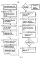
- Figure 3 shows a flow diagram of an asymmetric bandwidth assignment process executed by a controller.
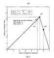
- Figure 4 depicts the nearest integer assignments of uplinks around a non-integer uplink assignment that provides maximum outbound capacity.
- Figure 5 shows an example of asymmetric bandwidth assignment in a satellite communication system.
- Figure 6 shows an example of asymmetric bandwidth assignment over three spot beams in a satellite communication system.
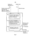
- Figure 7 illustrates a block diagram of a controller that may be used to distribute bandwidth in a communication system.
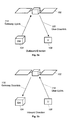
- the communication system 100 includes a satellite 102, gateway terminals 104, and user terminals 106. Also shown are a controller 108 and a monitor 110.
- the satellite 102 generates a spot beam 112 which supports uplinks and downlinks.
- Figure 1 shows a gateway terminal uplink 114, a gateway terminal downlink 116, a user terminal uplink 118, and a user terminal downlink 120.
- a signaling channel 122 is also present in Figure 1.
- one of the terminals involved in communicating through the satellite 102 is a high throughput terminal called a gateway (e.g., the gateway 104).
- the user terminals are generally smaller individual terminals, for example home computers or cellular phones.
- the user terminals may, for example, represent web browsing individuals and the gateways Internet Service Providers (ISPs).
- ISPs Internet Service Providers
- the user terminals typically send far less traffic to the gateways than the gateways send to the users. Ratios ranging between 5-to-1 and 20-to-1 are not unusual.
- the satellite 102 may be any type of communication satellite.
- the satellite 102 may be a bent-pipe satellite, an analog multiplexer satellite, an analog switch satellite, a digital processing satellite, or a hybrid type.
- the uplinks 114, 118 and downlinks 116, 120 may be of any modulation type and may have any physical make-up and link layer protocols.
- the uplinks may be formed using Frequency Division Multiplexing or Multiple Access (FDM / FDMA), Time Division Multiplexing or Multiple Access (TDM / TDMA), Code Division Multiple Access (CDMA) techniques, or combinations of such access techniques.
- FDM / FDMA Frequency Division Multiplexing or Multiple Access
- TDM / TDMA Time Division Multiplexing or Multiple Access
- CDMA Code Division Multiple Access
- the bandwidth providing individual frequency channels, time slots, or codes may be individually assigned, down to any available level of granularity, as described below, or entire uplinks and downlinks may be assigned as unitary entities constructed from numerous subchannels.
- the bandwidth assignment technique discussed below may further take into consideration features available onboard the satellite in order to maximize the effective capacity of the communication system. For example, when the satellite has a concentrating function such as a statistical multiplexer or concentrator (which removes some or all of the unused bandwidth in the uplinks before putting traffic in the downlinks), the invention may consider the presence of the concentrator in its determination of bandwidth assignments.
- a concentrating function such as a statistical multiplexer or concentrator (which removes some or all of the unused bandwidth in the uplinks before putting traffic in the downlinks)
- An example of bandwidth assignments taking into consideration the presence of a concentrator is set forth below.
- Figure 2a illustrates a satellite 102 forwarding communications from a gateway 104 to a user terminal 106.
- the direction of traffic flow from the gateway 104 to the user terminal 106 is referred to as the "outbound" direction.
- Traffic flow in the outbound direction travels over the gateway uplink 114 (i.e., the outbound uplink), through the satellite 102, and over the user downlink 120 (i.e., the outbound downlink) to the user terminal 106.
- Figure 2b shows that traffic flow in the "inbound" direction travels over the user uplink 118 (i.e., the inbound uplink), through the satellite 102, and over the gateway downlink 116 (i.e., the inbound downlink) to the gateway 104.
- the gateway downlink 116 i.e., the inbound downlink
- the controller 108 preferably makes and modifies bandwidth assignments, and may also be used in an initial planning role when developing a new communication system. Principal functions of the controller 108 include assigning satellite uplink and downlink bandwidth to the user terminals 106 and the gateways 104 and communicating these assignments to the user terminals 106 and the gateways 104.
- the assignments may be communicated in any number of ways including through terrestrial communication networks. In the preferred embodiment, however, the controller communicates assignments over a signaling channel 122 carried through the satellite 102 to the user terminals 106 and the gateways 104.
- the signaling channel 122 typically uses a very small amount of bandwidth and may be carried, for example, by any available uplink or downlink.
- the monitor 110 periodically evaluates the amount of bandwidth granted to and used by the user terminals 106 and the gateways 104 by using an antenna and processing circuitry or other monitoring hardware/software to evaluate traffic flow.
- the monitor 110 itself is optional.
- the controller 108 may operate using approximations or predetermined values.
- the monitor 110 may, in some instances, form a part of the controller 108 itself, although the monitor 110 may also be implemented as a remotely operating independent device (with appropriate communication connection to the controller 108).
- the controller 108 may make bandwidth assignments (discussed below) at a very fine or a very coarse level of refinement or granularity, depending upon the needs and capabilities of the communication system and the detail of information available.
- a communication system may only include the capability to assign bandwdith on the basis of entire uplinks or downlinks.
- a more sophisticated communication system may include the capability to assign bandwidth in terms of individual channels or subchannels (e.g., codes or time slots) in the uplinks and downlinks.
- the bandwidth assignments described below make the most efficient use of the available bandwidth in light of the granularity constraint imposed by the communication system.
- Table 1 presents the quantities that the controller 108 preferably considers in assigning uplinks and downlinks in its preferred implementation: Parameter Description R The ratio of outbound to inbound traffic.
- UE gwul The utilization efficiency of the gateway uplinks.
- UE uul The utilization efficiency of the user uplinks.
- UE gwdl The utilization efficiency of the gateway downlinks.
- UE uudl The utilization efficiency of the user downlinks.
- RelSize The ratio of the relative raw capacity of an uplink to the raw capacity of a downlink. Num up The number of available uplinks. Num down The number of available downlinks.
- the parameters in Table 1 may originate, for example, from an engineering or marketing study for a new communication system.
- UE The utilization efficiencies, provide estimates of the amount of traffic that may actually be sent in a unit amount of provisioned bandwidth. For example, a user uplink may operate with a UE uul of 20% or less due to contentious multiple access techniques (e.g., slotted ALOHA) used on the uplinks. With such techniques, high utilization leads to an unacceptable level of interference (and thus latency) between competing transmitters.
- contentious multiple access techniques e.g., slotted ALOHA
- operating a downlink near 100% of its capacity creates long queues on the satellite because aggregate traffic from numerous sources can exceed the downlink capacity. It is then possible for the queue to grow beyond available memory, resulting in data loss.
- a terminal with a 50% utilization efficiency that is expected, on average, to transmit 100kbps requires 200kbps of bandwidth.
- 100kbps of bandwidth is, on average, in use, while the other 100kbps of bandwidth provides extra capacity to immediately handle bursty traffic. Latency is thereby reduced by overproviding bandwidth.
- the terminal or gateway is assigned exactly the bandwidth it needs on average (i.e. there is no extra bandwidth capacity on average).
- the term RelSize gives the relative capacity of an uplink and a downlink without regard to the utilization efficiencies or loading of the links.
- a RelSize of 2 indicates that an uplink is able to carry twice as much traffic as a downlink.
- the terms Num up and Num down give the number of uplinks and downlinks available for assignment.
- the uplinks and downlinks are assigned in their entireties to the terminals.
- the subchannels within the uplinks and downlinks may be individually assigned according to the discussion and equations set forth below. Thus, for example, assigning 3.3 uplinks to user terminals may, in fact, indicate that 3 entire uplinks, and 3 of 10 subchannels of a fourth uplink are assigned to user terminals.
- the controller 108 determines a user uplink bandwidth metric.
- the controller 108 determines SUUB, the specific user uplink bandwidth.
- TentAssign gwul is the tentative gateway uplink assignment and TentAssign uul is the tentative user uplink assignment.
- equations [2] and [3] assign, in total, all the available uplinks either to the gateway or to the users, but that the assignments will not necessarily be whole numbers of uplinks. Such non-integer assignments are allowed if the uplinks may be shared between the users and gateways. Otherwise, the controller 108 adjusts the tentative assignments to whole numbers of uplinks.
- the tentative assignment of uplinks is an optimal allocation of uplinks in the sense that it maximizes the total traffic that the uplinks carry subject to the ratio R and the utilization efficiencies. Alternative assignments will carry less traffic. The further an alternate assignment varies from the tentative assignment, the less traffic that assignment carries.
- Figure 4 that figure illustrates a graph 400 of assignments of uplinks to a gateway, and the resulting outbound capacity used in the outbound direction.
- the graph 400 reflects the fact that user terminal inbound traffic generates the responsive outbound traffic from the gateway. Therefore, when the user terminals have less than a certain amount of uplink bandwidth for inbound transmissions, the gateway outbound traffic according falls.
- the point 402 illustrates the tentative assignment.
- the controller 108 preferably evaluates, at step 306, the integer solutions on either side of the tentative assignments to find the best realizable uplink assignment. That is, the controller 108 considers the assignments: and where ceiling(i) is the smallest integer greater than or equal to i and floor(j) is the greatest integer less than or equal to j.
- the controller 108 uses the actual traffic carried in the gateway uplinks as a measure of traffic carrying capacity of an assignment of UL gw uplinks to the gateways and UL u uplinks to the users. This measure is accurate because the traffic carried in the user uplinks is 1/R the traffic carried in the gateway uplinks.
- the controller determines CarriedUp for each of the assignments that result from equations [4A] and [4B] and then, at step 310, makes a final uplink assignment depending on which of the two assignments gives the greater capacity:
- the controller 108 proceeds to assign downlinks to the gateways and users.
- the controller 108 makes the assignments such that all the traffic offered to downlinks by the uplinks is carried to the ground. Such assignments may be achieved if the number of available downlinks and the utilization efficiencies of the downlinks are adequate. Otherwise, the controller 108 preferably delivers the greatest possible amount of traffic in the outbound and inbound directions. The controller 108 delivers this maximum using the approach outlined below.
- the controller determines the amount of traffic offered to the gateway downlinks and the user downlinks. This determination depends upon whether the satellite has a concentrating capability. In other words, the determination depends upon whether the satellite can discard unused uplink bandwidth before offering traffic to the downlinks.
- TO gwdl (1/R) CarriedUp (Assign gwul ,Assign uul ).
- the traffic offered to a downlink is adjusted to reflect the fact that only part of the uplink carries useful data. The rest does not carry traffic and is discarded before downlinking.
- TO udl Assign gwul
- TO gwdl Assign uul .
- the traffic offered to a downlink, without concentration is exactly equal to traffic arriving in the corresponding uplink. None is discarded.
- the controller 108 (at step 318) preferably assigns ceiling(Need gwdl ) downlinks to the gateways and ceiling(Need udl ) downlinks to the users. Any additional downlinks may be held in reserve or assigned in any manner desired.
- the controller 108 preferably finds an assignment that maximizes the overall throughput of the system, even if the assignment falls short of delivering all of the uplinked traffic.
- the uplinked traffic will be reduced to match the maximal downlink capacity that results from the assignment.
- the controller 108 assigns each downlink exclusively to the gateways or the users. In further systems, there may be uplinks that are not concentrated and that are therefore downlinked in their entirety (or else are abandoned). The operation of the controller 108 in these systems is explained below.
- the controller 108 examines the traffic-carrying capacity of alternative downlink assignments where each assignment is a whole number of downlinks. The controller 108 proceeds by working backward through the preceding equations from the alternative assignment of downlinks to the capacity.
- the measure of capacity is preferably the CarriedUp value obtained using equation [5].
- uplinked traffic is carried down in indivisible quanta of full uplinks. Therefore, without concentration, the controller 108 compensates by truncating values of ETO to whole integers (step 322).
- one restriction assumed in the non-concentrated traffic case is that the quotient (UE/RelSize) is greater than or equal to 1, otherwise the uplink would not fit into a downlink. Note also that if traffic is concentrated, the restriction does not apply.
- either or both of the outbound and inbound paths can be concentrated or not concentrated independently of the other.
- the present technique applies to each case, however. For example, in a non-concentrated path, the value of ETO will be compensated by truncation, while in the concentrated path it will not be truncated).
- the controller 108 preferably converts ETO to equivalent uplinks, EUL at step 324.
- EUL gw minimum(Assign gwul , ETO udl )
- EUL u minimum(Assign uul , ETO gwdl ) and, again, traffic carried, TC, is determined using equation [15].
- the controller 108 preferably repeats this process for all possible downlink assignments.
- the assignment which obtains the greatest value for TC is selected (step 328).
- the assignment values are put into Assign gwdl and Assign udl for communication to the gateways and users, in a bandwidth assignment message.
- the capacity of the system, TC is equal to the uplink capacity. Measuring this capacity as the capacity of the gateway uplinks (i.e., using CarriedUp gwul ), the capacity is 5.6 links worth of traffic.
- the controller would assign Assign gwul , Assign uul , Assign gwdl , and Assign udl each equal to 5.
- the asymmetric assignment carries 40% more traffic than the symmetric assignment.
- the controller 108 is used during system planning, the system designers will be alerted to the fact that only 7 downlinks are required to support 10 uplinks. By incorporating the asymmetry into the design of the system, critical satellite resources which would have been wasted can instead be used to support other beams and to increase the useful capacity of the satellite.
- Figures 5 and 6 next present additional examples of asymmetric bandwidth assignment.
- a communication system 500 including a bent-pipe non-concentrating satellite 502, a gateway 504, and numerous user terminals 506.
- a controller 508 is also present in the spot beam 510 generated by the satellite 502.
- Figure 5 further illustrates three gateway uplinks 512, a gateway downlink 514, three user terminal downlinks 516, a user terminal uplink 518, and a signaling channel 520.
- the way in which the uplinks 512, 518 and downlinks 514, 516 were assigned is explained below.
- the capacity of the communication system 500, TC is equal to the uplink capacity, or 3 units of traffic (assuming each uplink carries one unit of traffic).
- the controller would assign Assign gwul , Assign uul , Assign gwdl , and Assign udl each equal to 2.
- the asymmetric assignment carries 50% more traffic than the symmetric assignment.
- the satellite 302 provided the spot beam 310 with equal bandwidth in the uplinks 312, 318 and downlinks 314, 316. Although the total uplink and downlink bandwidth provided was balanced or equal, the controller 308 assigned it asymmetrically.
- Figure 6 illustrates application of the present method for assigning bandwidth in a more complicated communication system 600.
- Figure 6 illustrates a satellite 602 providing three spot beams (beaml 604, beam2 606, and beam3 608) of coverage for the communication system 600.
- Beam1 604 includes the user terminals 610
- beam2 606 includes the user terminals 612
- beam3 608 includes the user terminals 614, a controller 616, and a gateway and monitor 618.
- the satellite 602 carries a statistical multiplexer 620 (i.e., a concentrator).
- Figure 6 also illustrates a signaling channel 622 and numerous uplinks 626, 630, 634, and 636 and downlinks 624, 628, 632, and 638 (to be discussed in more detail below).
- Table 4 describes the parameters of the system shown in Figure 6: Parameter Value R 10 UE uul 0.3 UE gwul 1.0 UE udl 1.0 UE gwdl 1.0 RelSize 1.5 Num up 9 Num down 10
- Three user terminal downlinks 624, 628, 632 are allocated for each spot beam 604, 606, 608.
- the assignment illustrated in Figure 6 gives the communication system 600 a traffic capacity of 9 traffic units. Note also that the system designers do not need to include the circuitry for a tenth uplink (to match the 10 downlinks), because ten uplinks are not required for maximum throughput operation.
- a conventional assignment of bandwidth would result in 5 user uplinks and downlinks and 5 gateway uplinks and downlinks. It is very likely that each of beam1 604 and beam2 606 would have been assigned two user uplinks and downlinks, and beam3 608 would have been assigned one user uplink and downlink and four gateway uplinks and downlinks.
- the conventional system capacity would have been 5 traffic units.
- the bandwidth assignment distributed by the controller 616 increases system capacity by 80% in this example.
- the controller 616 creates an asymmetric provisioning of uplinks and downlinks.
- Beaml 604 and beam2 606 each are assigned three downlinks 624 (for user terminals 610), 628 (for user terminals 612) and one uplink 626 (for user terminals 610), 630 (for user terminals 612).
- beam3 608 three downlinks 632 and one uplink 634 are assigned to user terminals 614, while six uplinks 636 and one downlink 638 are assigned to the gateway 618.
- the asymmetric assignment greatly increases system capacity.
- the controller 700 includes input parameter determination circuitry 702, uplink and downlink assignment circuitry (assignment circuitry) 704, and communication circuitry 706.
- the controller 700 may receive input parameters from engineering or marketing inputs 708, or from a controller input 710.
- the controller 700 transmits uplink and downlink assignment information to gateway terminals and user terminals using the gateway output 712 and the user terminal output 714 (both of which, for example, may couple to a transmitter that sends information over a single signaling channel).
- the input parameter determination circuitry 702 directly accepts (from a marketing study, for example), or determines (from monitor 110 information) the parameters of interest in designing or operating a communication system.
- the input parameters preferably, correspond to those illustrated in Table 1.
- the assignment circuitry 704 determines, as described above, an assignment of uplinks and downlinks to the user terminals and the gateway terminals.
- the communication circuitry 706 creates an appropriate message (in any supported format) that relays the uplink and downlink assignments to the gateways and user terminals.
- the communication circuitry 706 may use, for example, a single signaling channel received by the user terminals and the gateways for this purpose.
- the controller 700 may be implemented using one or more general purpose CPUs, DSPs, or ASICs, or using discrete logic, either as a general programmed computer executing instructions from a memory, or as a hardware only implementation.
- the controller 700 may be used as both a planning tool and as an operational tool.
- the controller 700 may be used to determine the number of uplinks and downlink to be built into a communication system, determine the assignment of the uplinks and downlinks to gateways and user terminals, and determine (based on expectations of user take-up of service and on the planned locations of the gateways) the number of uplinks and downlinks to be placed in each satellite beam.
- the planning tool first stores given or predetermined input parameters, and may be used to determine the remaining parameters (e.g., Num down ) in view of the equations above.
- the controller 700 may be used to periodically (e.g., once per day, week, month, or year) allocate and reallocate uplinks and downlinks on a semi-permanent or dynamically changing basis in an existing communication system.
- controller 700 may be onboard the satellite or on the ground. If the controller 700 is on the ground, it may be co-located with other ground elements or located away from the ground elements with a suitable wire or wireless interconnection, whichever is preferable in the system design. As noted above, the controller 700 may also be used to determine, with multiple gateways and satellite beams, the distribution of uplinks and downlinks in the many beams rather than only determining the number of uplinks and downlinks assigned to gateways and users.
- the present invention assigns communication bandwidth based in part on the asymmetry in inbound and outbound communication between terminals through a satellite.
- the bandwidth assignments are tailored to the actual needs of the terminals in terms of both bandwidth and latency. As a result, the bandwidth assignments significantly increase the communication capacity, revenue, and throughput of the communication system.
Abstract
Description
- The present invention relates to assignment of bandwidth resources in a communication system. In particular, the present invention relates to asymmetric assignment of communication bandwidth in a satellite communications system.
- Communication networks transmit and receive staggering amounts of information that may have virtually any origin including, for example, the Internet, the public telephone system, and television stations. In modern communication systems, a considerable portion of the information may be multiplexed into data streams and transmitted over satellite uplinks and downlinks before reaching its destination. Thus, for example, Internet service providers (ISPs) could transmit information through a satellite to numerous individual receivers.
- In order to accommodate the tremendous demand for communication bandwidth, modern communication satellites provide uplink and downlink capacities of many gigabits per second. Of course, modern communication satellites are extremely expensive to design, launch, and operate. Thus, a new communication satellite cannot simply be launched whenever convenient to increase bandwidth in a communication system. Rather, the bandwidth provided by existing communication satellites must be assigned so that it is most efficiently used while generating the most revenue.
- In the past, however, communication system controllers assigned equal uplink and downlink bandwidth to individual terminals or groups of terminals. While providing a simple solution to bandwidth allocation, equal assignment of uplink and downlink bandwidth ignored the fact that in many situations, uplink and downlink bandwidth needs are dramatically different. For example, in the ISP setting, a home computer terminal typically receives between 5 and 20 times more information than it transmits.
- In such situations, an equal assignment of uplink and downlink bandwidth to the terminal results in a significant waste of uplink bandwidth. In turn, wasted bandwidth significantly decreases the communication system revenues, efficiency, and throughput. Furthermore, some communication system controllers already purposefully overprovide bandwidth to terminals to reduce latency. Thus, any additional bandwidth assigned, but not used by terminals, has a further negative impact on system revenue, throughput, and efficiency.
- A need has long existed in the industry for an improved method and apparatus for assignment of communication bandwidth in a space-borne communications system.
- One aspect of the present invention is asymmetric assignment of bandwidth in a communication system.
- Another aspect of the present invention is asymmetric assignment of uplink and downlink bandwidth in a satellite communication system.
- One feature of the present invention is Assignment of bandwidth in a communication system that considers uplink and downlink utilization efficiencies, outbound to inbound traffic ratio, and other input parameters.
- Yet another feature of the present invention is the assignment of uplink and downlink bandwidth in a satellite communication system that accounts for concentrators onboard a satellite.
- The present method for allocating bandwidth in a satellite communication system includes the step of determining an assignment of uplinks to user terminals and one or more gateways. The uplink assignment is preferably based on a gateway uplink efficiency, a user terminal uplink efficiency, and a traffic ratio between the user terminal and the gateways. The method also determines an assignment of downlinks to the user terminals and the gateways. The downlink assignment is preferably based on traffic offered to the user terminals and the gateways as dictated by the uplink assignment.
- Either of the uplink assignment and downlink assignments may be integer or non-integer assignments. Integer and non-integer assignments may be used when the uplinks and/or downlinks are divisible into assignable subchannels. Integer assignments may be used when the uplinks are indivisible. In some instances, the assignment that maximizes outbound capacity is a non-integer assignment. In cases where the uplinks and downlinks are indivisible, the present method may then evaluate integer assignments of uplinks around the non-integer assignment to determine an integer assignment that most closely matches the maximal outbound capacity.
- The present method, in determining the downlink assignments, preferably considers the relative size (i.e., capacity) of uplinks compared to downlinks. The method may further determine the desired number of downlinks needed for a gateway and the user terminals to meet the bandwidth demands resulting from the uplink assignments. When the number of available downlinks is sufficient, the method assigns the desired number of downlinks. Otherwise, the method preferably evaluates assignments of downlinks to the user terminals and gateways to find a capacity maximizing downlink assignment given the total number of available downlinks.
- The present satellite communication system bandwidth controller includes uplink and downlink assignment circuitry and communication circuitry. The assignment circuitry is operable to determine an assignment of uplinks to user terminals and gateways, based on a gateway uplink efficiency, a user terminal uplink efficiency, and a traffic ratio between the user terminal and the gateway among other information. The assignment circuitry is also operable to determine an assignment of downlinks to the user terminals and the gateways, based on traffic offered to the user terminals and the gateways according to the uplink assignment.
- The bandwidth controller may further include input parameter determination circuitry for determining the gateway uplink efficiency, user terminal uplink efficiency, and the traffic ratio, by receiving the parameters as design inputs or by evaluating a communication system monitor input. The bandwidth controller may be disposed onboard a satellite, or on the ground at a location nearby or remote from the gateways or user terminals. In one embodiment, the bandwidth controller evaluates a communication system in operation and responsively dynamically adjusts the uplink and downlink assignments. In another embodiment, the bandwidth controller evaluates uplink and downlink assignments in advance for a planned communication system. As noted above, the uplink and downlink assignments may be integer or non-integer, and may further take into consideration the presence or absence of a multiplexer or concentrator onboard a satellite.
- Figure 1 introduces the entities involved in a satellite communication system.
- Figure 2 illustrates the inbound and outbound direction of traffic in a satellite communication system.
- Figure 3 shows a flow diagram of an asymmetric bandwidth assignment process executed by a controller.
- Figure 4 depicts the nearest integer assignments of uplinks around a non-integer uplink assignment that provides maximum outbound capacity.
- Figure 5 shows an example of asymmetric bandwidth assignment in a satellite communication system.
- Figure 6 shows an example of asymmetric bandwidth assignment over three spot beams in a satellite communication system.
- Figure 7 illustrates a block diagram of a controller that may be used to distribute bandwidth in a communication system.
- Turning now to Figure 1, that figure illustrates the entities involved in a
satellite communication system 100. Thecommunication system 100 includes asatellite 102,gateway terminals 104, anduser terminals 106. Also shown are acontroller 108 and amonitor 110. Thesatellite 102 generates aspot beam 112 which supports uplinks and downlinks. For example, Figure 1 shows agateway terminal uplink 114, agateway terminal downlink 116, auser terminal uplink 118, and auser terminal downlink 120. Asignaling channel 122 is also present in Figure 1. - In a preferred implementation, one of the terminals involved in communicating through the
satellite 102 is a high throughput terminal called a gateway (e.g., the gateway 104). The user terminals are generally smaller individual terminals, for example home computers or cellular phones. The user terminals may, for example, represent web browsing individuals and the gateways Internet Service Providers (ISPs). The user terminals typically send far less traffic to the gateways than the gateways send to the users. Ratios ranging between 5-to-1 and 20-to-1 are not unusual. - The
satellite 102 may be any type of communication satellite. For example, thesatellite 102 may be a bent-pipe satellite, an analog multiplexer satellite, an analog switch satellite, a digital processing satellite, or a hybrid type. Theuplinks downlinks - The bandwidth assignment technique discussed below may further take into consideration features available onboard the satellite in order to maximize the effective capacity of the communication system. For example, when the satellite has a concentrating function such as a statistical multiplexer or concentrator (which removes some or all of the unused bandwidth in the uplinks before putting traffic in the downlinks), the invention may consider the presence of the concentrator in its determination of bandwidth assignments. An example of bandwidth assignments taking into consideration the presence of a concentrator is set forth below.
- Turning now to Figures 2a-2b, those figures illustrate the inbound and outbound direction of traffic travelling between terminals. In particular, Figure 2a illustrates a
satellite 102 forwarding communications from agateway 104 to auser terminal 106. The direction of traffic flow from thegateway 104 to theuser terminal 106 is referred to as the "outbound" direction. Traffic flow in the outbound direction travels over the gateway uplink 114 (i.e., the outbound uplink), through thesatellite 102, and over the user downlink 120 (i.e., the outbound downlink) to theuser terminal 106. Similarly, Figure 2b shows that traffic flow in the "inbound" direction travels over the user uplink 118 (i.e., the inbound uplink), through thesatellite 102, and over the gateway downlink 116 (i.e., the inbound downlink) to thegateway 104. - Referring again to Figure 1, the
controller 108 preferably makes and modifies bandwidth assignments, and may also be used in an initial planning role when developing a new communication system. Principal functions of thecontroller 108 include assigning satellite uplink and downlink bandwidth to theuser terminals 106 and thegateways 104 and communicating these assignments to theuser terminals 106 and thegateways 104. The assignments may be communicated in any number of ways including through terrestrial communication networks. In the preferred embodiment, however, the controller communicates assignments over a signalingchannel 122 carried through thesatellite 102 to theuser terminals 106 and thegateways 104. The signalingchannel 122 typically uses a very small amount of bandwidth and may be carried, for example, by any available uplink or downlink. - The
monitor 110 periodically evaluates the amount of bandwidth granted to and used by theuser terminals 106 and thegateways 104 by using an antenna and processing circuitry or other monitoring hardware/software to evaluate traffic flow. Themonitor 110 itself is optional. When themonitor 110 is not present, thecontroller 108 may operate using approximations or predetermined values. In addition, themonitor 110 may, in some instances, form a part of thecontroller 108 itself, although themonitor 110 may also be implemented as a remotely operating independent device (with appropriate communication connection to the controller 108). - Note that the
controller 108 may make bandwidth assignments (discussed below) at a very fine or a very coarse level of refinement or granularity, depending upon the needs and capabilities of the communication system and the detail of information available. In other words, a communication system may only include the capability to assign bandwdith on the basis of entire uplinks or downlinks. On the other hand, a more sophisticated communication system may include the capability to assign bandwidth in terms of individual channels or subchannels (e.g., codes or time slots) in the uplinks and downlinks. The bandwidth assignments described below make the most efficient use of the available bandwidth in light of the granularity constraint imposed by the communication system. - Table 1 presents the quantities that the
controller 108 preferably considers in assigning uplinks and downlinks in its preferred implementation:Parameter Description R The ratio of outbound to inbound traffic. UEgwul The utilization efficiency of the gateway uplinks. UEuul The utilization efficiency of the user uplinks. UEgwdl The utilization efficiency of the gateway downlinks. UEuudl The utilization efficiency of the user downlinks. RelSize The ratio of the relative raw capacity of an uplink to the raw capacity of a downlink. Numup The number of available uplinks. Numdown The number of available downlinks. - The parameters in Table 1 may originate, for example, from an engineering or marketing study for a new communication system. The ratio R is the presumed "native" asymmetry in the way a communication system operates. For example, as indicated above in the context of ISPs and web surfers, R may range from 5:1 (R=5) to 20:1 (R=20).
- The utilization efficiencies, UE, provide estimates of the amount of traffic that may actually be sent in a unit amount of provisioned bandwidth. For example, a user uplink may operate with a UEuul of 20% or less due to contentious multiple access techniques (e.g., slotted ALOHA) used on the uplinks. With such techniques, high utilization leads to an unacceptable level of interference (and thus latency) between competing transmitters. In a similar fashion, operating a downlink near 100% of its capacity creates long queues on the satellite because aggregate traffic from numerous sources can exceed the downlink capacity. It is then possible for the queue to grow beyond available memory, resulting in data loss.
- As an example, a terminal with a 50% utilization efficiency that is expected, on average, to transmit 100kbps requires 200kbps of bandwidth. In this example, 100kbps of bandwidth is, on average, in use, while the other 100kbps of bandwidth provides extra capacity to immediately handle bursty traffic. Latency is thereby reduced by overproviding bandwidth. In some instances, as will be seen below, the terminal or gateway is assigned exactly the bandwidth it needs on average (i.e. there is no extra bandwidth capacity on average).
- Continuing the description of the parameters shown in Table 1, the term RelSize gives the relative capacity of an uplink and a downlink without regard to the utilization efficiencies or loading of the links. In other words, a RelSize of 2 indicates that an uplink is able to carry twice as much traffic as a downlink. The terms Numup and Numdown give the number of uplinks and downlinks available for assignment. In one implementation, as noted above, the uplinks and downlinks are assigned in their entireties to the terminals. In more sophisticated implementations, the subchannels within the uplinks and downlinks may be individually assigned according to the discussion and equations set forth below. Thus, for example, assigning 3.3 uplinks to user terminals may, in fact, indicate that 3 entire uplinks, and 3 of 10 subchannels of a fourth uplink are assigned to user terminals.
- Turning now to Figure 3, that figure presents a flow diagram 300 showing the processing that occurs in a preferred implementation of the
controller 108. Atstep 302, thecontroller 108 determines a user uplink bandwidth metric. In particular, thecontroller 108 determines SUUB, the specific user uplink bandwidth. The SUUB parameter combines the two uplink utilization efficiencies and the outbound-to-inbound traffic ratio to indicate to thecontroller 108 how much user uplink bandwidth to assign per unit of gateway uplink bandwidth: - Next, at
step 304, the controller tentatively divides the available uplinks between the gateway and the user terminals according to equations [2] and [3]:
- TentAssigngwul is the tentative gateway uplink assignment and TentAssignuul is the tentative user uplink assignment. Note that equations [2] and [3] assign, in total, all the available uplinks either to the gateway or to the users, but that the assignments will not necessarily be whole numbers of uplinks. Such non-integer assignments are allowed if the uplinks may be shared between the users and gateways. Otherwise, the
controller 108 adjusts the tentative assignments to whole numbers of uplinks. - The tentative assignment of uplinks is an optimal allocation of uplinks in the sense that it maximizes the total traffic that the uplinks carry subject to the ratio R and the utilization efficiencies. Alternative assignments will carry less traffic. The further an alternate assignment varies from the tentative assignment, the less traffic that assignment carries.
- Turning briefly to Figure 4, that figure illustrates a
graph 400 of assignments of uplinks to a gateway, and the resulting outbound capacity used in the outbound direction. Thegraph 400 reflects the fact that user terminal inbound traffic generates the responsive outbound traffic from the gateway. Therefore, when the user terminals have less than a certain amount of uplink bandwidth for inbound transmissions, the gateway outbound traffic according falls. Figure 4 shows a scenario in which Numup = 7, R = 10, UEgwul = 1.0, and UEuul = 0.3. According to equations [1], [2], and [3], TentAssigngwul = 5.25 and TentAssignuul = 1.75; because UEgwul = 1.0, the outbound capacity is 5.25 units of traffic. Thepoint 402 illustrates the tentative assignment. - As noted above, in some systems, the
controller 108 may only assign integer numbers of uplinks or downlinks. In such a system, thecontroller 108 evaluates the integer assignments around the tentative assignment (if it is not already an integer assignment). Thus, in Figure 4, thecontroller 108 evaluates the outbound traffic carried by assigning 5 uplinks to the gateway and 2 uplinks to the user terminals (point 404) or 4 uplinks to the gateway and 3 uplinks to the user terminals (point 406). Atpoint 404, the outbound capacity is 5 full units. Atpoint 406, the outbound capacity is only 3 units (although allocated 6 full uplinks that can carry 6 full units of traffic). Because the one remaining uplink, assigned to the user terminals at UEuul = 0.3 (or 0.3 units of traffic on average) only results in R = 10 times as much (3 units) outbound traffic. - Returning to Figure 3, the
controller 108 preferably evaluates, atstep 306, the integer solutions on either side of the tentative assignments to find the best realizable uplink assignment. That is, thecontroller 108 considers the assignments:and where ceiling(i) is the smallest integer greater than or equal to i and floor(j) is the greatest integer less than or equal to j.
- In one implementation, the
controller 108 uses the actual traffic carried in the gateway uplinks as a measure of traffic carrying capacity of an assignment of ULgw uplinks to the gateways and ULu uplinks to the users. This measure is accurate because the traffic carried in the user uplinks is 1/R the traffic carried in the gateway uplinks. - In the scenario shown in Figure 4,
- AssignAgwul = 6
- AssignAuul = 1 and
- AssignBgwul = 5
- AssignBuul = 2
-
- Next, at
step 308, the controller determines traffic carried in the gateway uplinks according to: - The controller determines CarriedUp for each of the assignments that result from equations [4A] and [4B] and then, at
step 310, makes a final uplink assignment depending on which of the two assignments gives the greater capacity: - If CarriedUp(AssignAgwul,AssignAuul) is greater than or equal to CarriedUp(AssignBgwul,AssignBuul) thenOtherwise,


- Again, in the scenario shown in Figure 4 (which is carried through in the equations below):
CarriedUp(AssignAgwul, AssignAuul) = 3, which is less than CarriedUp(AssignBgwul,AssignBuul) = 5 and therefore: - Assigngwul = AssignBgwul = 5, and
- Assignuul = AssignBuul = 2.
-
- Next, as shown by
transition arrow 312, thecontroller 108 proceeds to assign downlinks to the gateways and users. Preferably, thecontroller 108 makes the assignments such that all the traffic offered to downlinks by the uplinks is carried to the ground. Such assignments may be achieved if the number of available downlinks and the utilization efficiencies of the downlinks are adequate. Otherwise, thecontroller 108 preferably delivers the greatest possible amount of traffic in the outbound and inbound directions. Thecontroller 108 delivers this maximum using the approach outlined below. - First, at
step 314, the controller determines the amount of traffic offered to the gateway downlinks and the user downlinks. This determination depends upon whether the satellite has a concentrating capability. In other words, the determination depends upon whether the satellite can discard unused uplink bandwidth before offering traffic to the downlinks. - The traffic offered (TO) to the user downlinks and the gateway downlinks, if the satellite concentrates traffic, is:
- In other words, the traffic offered to a downlink, with concentration, is adjusted to reflect the fact that only part of the uplink carries useful data. The rest does not carry traffic and is discarded before downlinking.
- The traffic offered (TO) to the user downlinks and the gateway downlinks, if the satellite does not concentrate outbound traffic, is:
- In other words, the traffic offered to a downlink, without concentration, is exactly equal to traffic arriving in the corresponding uplink. Nothing is discarded.
- The controller, at
step 316, next combines the offered traffic values, the relative size of uplinks compared with downlinks, and the utilization efficiencies of the downlinks to determine the need for downlink bandwidth using the following equations: - Assuming that RelSize = 2, with concentration, in the example of Figure 4, and UEgwdl = 0.7 and UEudl = 1.0, then
- If ceiling(Needgwdl) + ceiling (Needudl) is less than or equal to Numdown, the controller 108 (at step 318) preferably assigns ceiling(Needgwdl) downlinks to the gateways and ceiling(Needudl) downlinks to the users. Any additional downlinks may be held in reserve or assigned in any manner desired.
- Conversely, if Numdown is inadequate to meet the total need, the
controller 108 preferably finds an assignment that maximizes the overall throughput of the system, even if the assignment falls short of delivering all of the uplinked traffic. In an actual system implementation, the uplinked traffic will be reduced to match the maximal downlink capacity that results from the assignment. - In a system in which downlinks are divisible and in which fractions of uplinks may be downlinked, the optimal assignment is:
- For the example of Figure 4, assuming Numdown = 10:
- In some systems, however, the
controller 108 assigns each downlink exclusively to the gateways or the users. In further systems, there may be uplinks that are not concentrated and that are therefore downlinked in their entirety (or else are abandoned). The operation of thecontroller 108 in these systems is explained below. - The
controller 108 examines the traffic-carrying capacity of alternative downlink assignments where each assignment is a whole number of downlinks. Thecontroller 108 proceeds by working backward through the preceding equations from the alternative assignment of downlinks to the capacity. The measure of capacity is preferably the CarriedUp value obtained using equation [5]. - The
controller 108 considers alternative assignments of DLgw downlinks assigned to gateways and DLu downlinks assigned to user terminals (step 320). Thecontroller 108 then preferably determines the capacity of the downlinks to carry traffic offered to them. Equations [7] and [8] may be modified to produce equivalent traffic offered, ETO equations shown below in equations [11] and [12]. The ETO is the amount of offered traffic that would fill the downlink assignment currently under consideration. (ETO is measured in units equal to the capacity of an uplink.) - Assuming for example, that the
controller 108 is evaluating an assignment DLgw = 3 and DLu = 7, then: - If uplinked traffic is not concentrated, then the uplinked traffic is carried down in indivisible quanta of full uplinks. Therefore, without concentration, the
controller 108 compensates by truncating values of ETO to whole integers (step 322). Note that one restriction assumed in the non-concentrated traffic case is that the quotient (UE/RelSize) is greater than or equal to 1, otherwise the uplink would not fit into a downlink. Note also that if traffic is concentrated, the restriction does not apply. - It is further noted that either or both of the outbound and inbound paths can be concentrated or not concentrated independently of the other. The present technique applies to each case, however. For example, in a non-concentrated path, the value of ETO will be compensated by truncation, while in the concentrated path it will not be truncated).
- Next, the
controller 108 preferably converts ETO to equivalent uplinks, EUL atstep 324. Equivalent uplinks are the number of uplinks which would offer ETO traffic to the downlinks when the uplink utilization efficiency is taken into account. Again, a distinction is preferably made between concentrating and non-concentrating directions through the satellite. If both directions are concentrated, then the EUL are evaluated using: - The
controller 108, atstep 326, determines traffic carried as: - For the example of Figure 4:
- If neither path is concentrated, then the EUL are evaluated using:
- For the example under consideration:
- If one path is concentrated while the other is not, then the EUL are found by choosing from among equations [13], [14], [16], and [17] according to the paths that are concentrated, and applying equation [15] to the result.
- The
controller 108 preferably repeats this process for all possible downlink assignments. The assignment which obtains the greatest value for TC is selected (step 328). The assignment values are put into Assigngwdl and Assignudl for communication to the gateways and users, in a bandwidth assignment message. - As another example, assume a concentrating satellite which allocates uplinks and downlinks in their entirety to users or gateways. The relevant input quantities are shown in Table 1:
Parameter Value R 10 UEgwul 0.8 UEuul 0.2 UEgwdl 0.7 UE udl1 RelSize 1 Numup 10 Numdown 10 - The values obtained from the equations above are:
- [1] SUUB = (0.8 / 0.2) / 10 = 0.4
- [2] TentAssigngwul = 10/(1 + 0.4) = 7.14
- [3] TentAssignuul = 10 * 0.4 / (1 + 0.4) = 2.86
- [4A] AssignAgwul = 8, Assignuul = 2
- [4B] Assigngwul = 7, Assignuul = 3
- [5] CarriedUp applied to [4A] yields 4 CarriedUp applied to [4B] yields 5.6
- [6A] Does not apply.
- [6B] Assigngwul = 7, Assignuul = 3
Because the satellite concentrates in both the inbound
and outbound directions, the traffic offered is found as:
- [7] Needgwdl = 1 * 0.56 / 0.7 = 0.8
- [8] Needudl = 1 * 5.6 / 1 = 5.6
-
- Since ceiling(Needgwdl) + ceiling(Needudl) = 1 + 6 <= 10, the
controller 108 sets Assigngwdl = 1 and Assignudl = 6. - Since the capacity is not limited by the downlink side, the capacity of the system, TC, is equal to the uplink capacity. Measuring this capacity as the capacity of the gateway uplinks (i.e., using CarriedUpgwul), the capacity is 5.6 links worth of traffic.
- Using a conventional symmetric assignment, the controller would assign Assigngwul, Assignuul, Assigngwdl, and Assignudl each equal to 5. The system would be constrained by the capacity of the gateway uplinks (5 * 0.8 = 4 links worth of traffic). Thus, the asymmetric assignment carries 40% more traffic than the symmetric assignment. Further, if the
controller 108 is used during system planning, the system designers will be alerted to the fact that only 7 downlinks are required to support 10 uplinks. By incorporating the asymmetry into the design of the system, critical satellite resources which would have been wasted can instead be used to support other beams and to increase the useful capacity of the satellite. - With the general aspects of the current technique set forth above, Figures 5 and 6 next present additional examples of asymmetric bandwidth assignment. Turning now to Figure 5, that figure illustrates a
communication system 500 including a bent-pipe non-concentrating satellite 502, agateway 504, andnumerous user terminals 506. Acontroller 508 is also present in thespot beam 510 generated by thesatellite 502. Figure 5 further illustrates threegateway uplinks 512, agateway downlink 514, three user terminal downlinks 516, auser terminal uplink 518, and asignaling channel 520. The way in which theuplinks downlinks - For the
communication system 500, the following parameters set forth in Table 3 are assumed to apply:Parameter Value R 10 UEuul 0.3 UEgwul 1.0 UEudl 1.0 UEgwdl 1.0 RelSize 1 Num up4 Num down4 - Evaluating the equations above yields:
- [1] SUUB = (1 / 0.3) / 10 = 0.33
- [2] TentAssigngwul = 4 / (1 + 0.33) = 3.01
- [3] TentAssignuul = 4 * 0.33 / (1 + 0.33) = 0.99
- [4A] AssignAgwul = 4, Assignuul = 0
- [4B] Assigngwul = 3, Assignuul = 1
- [5] CarriedUp applied to [4A] yields 0 CarriedUp applied to [4B] yields 3
- [6A] Does not apply.
- [6B] Assigngwul = 3, Assignuul = 1
Because the satellite does not concentrate, the traffic
offered is found as:
- [7] Needgwdl = 1 * 1 / 1 = 1
- [8] Needudl = 1 * 3 / 1 = 3
-
- Since ceiling(Needgwdl) + ceiling(Needudl) = 1 + 3 <= 4, the
controller 508 sets Assigngwdl = 1 and Asisgnudl = 3. - The capacity of the
communication system 500, TC, is equal to the uplink capacity, or 3 units of traffic (assuming each uplink carries one unit of traffic). Using a conventional symmetric assignment, however, the controller would assign Assigngwul, Assignuul, Assigngwdl, and Assignudl each equal to 2. The system would by constrained by the capacity of the gateway uplinks (2 * 1 = 2 units of traffic). Thus, the asymmetric assignment carries 50% more traffic than the symmetric assignment. Note that thesatellite 302 provided thespot beam 310 with equal bandwidth in theuplinks downlinks controller 308 assigned it asymmetrically. - Figure 6 illustrates application of the present method for assigning bandwidth in a more
complicated communication system 600. Figure 6 illustrates asatellite 602 providing three spot beams (beaml 604,beam2 606, and beam3 608) of coverage for thecommunication system 600.Beam1 604 includes theuser terminals 610,beam2 606 includes the user terminals 612, and beam3 608 includes theuser terminals 614, acontroller 616, and a gateway and monitor 618. Note also that thesatellite 602 carries a statistical multiplexer 620 (i.e., a concentrator). Figure 6 also illustrates asignaling channel 622 andnumerous uplinks downlinks - Table 4 describes the parameters of the system shown in Figure 6:
Parameter Value R 10 UEuul 0.3 UEgwul 1.0 UEudl 1.0 UEgwdl 1.0 RelSize 1.5 Numup 9 Numdown 10 - Evaluation of the equations above yields:
- [1] SUUB = (1 / 0.3) / 10 = 0.33
- [2] TentAssigngwul = 9 / (1 + 0.33) = 6.77
- [3] TentAssignuul = 9 * 0.33 / (1 + 0.33) = 2.23
- [4A] AssignAgwul = 7, Assignuul = 2
- [4B] Assigngwul = 6, Assignuul = 3
- [5] CarriedUp applied to [4A] yields 6 CarriedUp applied to [4B] yields 6
- [6A] Does not apply.
- [6B] Assigngwul = 6, Assignuul = 3, since the
communication system 600 needs at least 3 uplinks to support the threedifferent beams satellite 602 concentrates, the traffic offered is: - [7] Needgwdl = 1.5 * 0.6 / 1 = 0.9
- [8] Needudl = 1.5 * 6 / 1 = 9
-
- Since ceiling(Needgwdl) + ceiling(Needudl) = 1 + 9 = 10 <= 10, the
controller 616 sets Assigngwdl = 1 and Asisgnudl = 9. Three user terminal downlinks 624, 628, 632 are allocated for eachspot beam - The assignment illustrated in Figure 6 gives the communication system 600 a traffic capacity of 9 traffic units. Note also that the system designers do not need to include the circuitry for a tenth uplink (to match the 10 downlinks), because ten uplinks are not required for maximum throughput operation. In this example, a conventional assignment of bandwidth would result in 5 user uplinks and downlinks and 5 gateway uplinks and downlinks. It is very likely that each of
beam1 604 andbeam2 606 would have been assigned two user uplinks and downlinks, and beam3 608 would have been assigned one user uplink and downlink and four gateway uplinks and downlinks. The conventional system capacity would have been 5 traffic units. The bandwidth assignment distributed by thecontroller 616 increases system capacity by 80% in this example. - In the
communication system 600, however, thecontroller 616 creates an asymmetric provisioning of uplinks and downlinks.Beaml 604 andbeam2 606 each are assigned three downlinks 624 (for user terminals 610), 628 (for user terminals 612) and one uplink 626 (for user terminals 610), 630 (for user terminals 612). Inbeam3 608, threedownlinks 632 and oneuplink 634 are assigned touser terminals 614, while sixuplinks 636 and onedownlink 638 are assigned to thegateway 618. The asymmetric assignment greatly increases system capacity. - Turning now to figure 7, that figure illustrates a block diagram of a
controller 700 that may be used to determine bandwidth distributions as described above. Thecontroller 700 includes inputparameter determination circuitry 702, uplink and downlink assignment circuitry (assignment circuitry) 704, andcommunication circuitry 706. Thecontroller 700 may receive input parameters from engineering ormarketing inputs 708, or from acontroller input 710. Thecontroller 700 transmits uplink and downlink assignment information to gateway terminals and user terminals using thegateway output 712 and the user terminal output 714 (both of which, for example, may couple to a transmitter that sends information over a single signaling channel). - In operation, the input
parameter determination circuitry 702 directly accepts (from a marketing study, for example), or determines (frommonitor 110 information) the parameters of interest in designing or operating a communication system. The input parameters, preferably, correspond to those illustrated in Table 1. With the input parameters known, theassignment circuitry 704 determines, as described above, an assignment of uplinks and downlinks to the user terminals and the gateway terminals. After theassignment circuitry 704 determines the appropriate distribution of uplinks and downlinks, thecommunication circuitry 706 creates an appropriate message (in any supported format) that relays the uplink and downlink assignments to the gateways and user terminals. Thecommunication circuitry 706 may use, for example, a single signaling channel received by the user terminals and the gateways for this purpose. As a general matter, thecontroller 700 may be implemented using one or more general purpose CPUs, DSPs, or ASICs, or using discrete logic, either as a general programmed computer executing instructions from a memory, or as a hardware only implementation. - Note that the
controller 700 may be used as both a planning tool and as an operational tool. As a planning tool, thecontroller 700 may be used to determine the number of uplinks and downlink to be built into a communication system, determine the assignment of the uplinks and downlinks to gateways and user terminals, and determine (based on expectations of user take-up of service and on the planned locations of the gateways) the number of uplinks and downlinks to be placed in each satellite beam. The planning tool first stores given or predetermined input parameters, and may be used to determine the remaining parameters (e.g., Numdown) in view of the equations above. As an operational tool, thecontroller 700 may be used to periodically (e.g., once per day, week, month, or year) allocate and reallocate uplinks and downlinks on a semi-permanent or dynamically changing basis in an existing communication system. - It is further noted that the
controller 700 may be onboard the satellite or on the ground. If thecontroller 700 is on the ground, it may be co-located with other ground elements or located away from the ground elements with a suitable wire or wireless interconnection, whichever is preferable in the system design. As noted above, thecontroller 700 may also be used to determine, with multiple gateways and satellite beams, the distribution of uplinks and downlinks in the many beams rather than only determining the number of uplinks and downlinks assigned to gateways and users. - Thus, the present invention assigns communication bandwidth based in part on the asymmetry in inbound and outbound communication between terminals through a satellite. The bandwidth assignments are tailored to the actual needs of the terminals in terms of both bandwidth and latency. As a result, the bandwidth assignments significantly increase the communication capacity, revenue, and throughput of the communication system.
- While particular elements, embodiments and applications of the present invention have been shown and described, it is understood that the invention is not limited thereto since modifications may be made by those skilled in the art, particularly in light of the foregoing teaching. It is therefore contemplated by the appended claims to cover such modifications and incorporate those features which come within the spirit and scope of the invention.
Claims (15)
- A method for allocating bandwidth in a satellite communication system, the method comprising:determining an uplink assignment of uplinks to user terminals and a gateway, based on a gateway uplink efficiency, a user terminal uplink efficiency, and a traffic ratio between the user terminal and the gateway; anddetermining a downlink assignment of downlinks to the user terminals and the gateway, based on traffic offered to the user terminals and the gateway according to the uplink assignment.
- A method according to claim 1, wherein the step of determining an uplink assignment further comprises determining a non-integer uplink assignment based on subchannels forming an uplink.
- A method according to claim 1, wherein the step of determining a downlink assignment further comprises determining a non-integer downlink assignment based on subchannels forming a downlink.
- A method according to claim 1, wherein the step of determining an uplink assignment further comprises determining an integer uplink assignment by evaluating integer assignments of uplinks around a non-integer assignment of uplinks yielding maximum outbound capacity.
- A method according to claim 4, wherein the step of determining an uplink assignment selects the maximum of:in accordance with:CarriedUp (AssignAgwul, AssignAuul)=minimum(AssignAgwul *UEgwul, R* AssignAuul *UEuul) andCarriedUp (AssignBgwul, AssignBuul) =minimum (AssignBgwul *UEqwul, R* AssignBuul *UEuul),where TentAssigngwul is a tentative assignment of uplinks to the gateway, Numup is a total number of communication system uplinks, SUUB is a specific user bandwidth, TentAssignuul = is a tentative assignment of uplinks to the user terminals, R is an outbound to inbound traffic ratio, UEgwul is a utilization efficiency of a gateway uplink, and UEuul is a utilization efficiency of a user terminal uplink.TentAssigngwul = Numup / (1 + SUUB),SUUB = (UEgwul / UEuul) / R,TentAssignuul = Numup - TentAssigngwul,AssignAgwul = ceiling(TentAssigngwul),AssignAuul = floor(TentAssignuul),AssignBgwul = floor(TentAssigngwul),AssignBuul = ceiling(TentAssignuul),
- A method according to claim 3, wherein the step of determining an uplink assignment comprises determining:in accordance with:CarriedUp(AssignAgwul, AssignAuul) =minimum (AssignAgwul * UEgwul, R* AssignAuul *UEuul) andCarriedUp (AssignBgwul, AssignBuul) =minimum (AssignBgwul * UEgwul, R* AssignBuul *UEuul),where Assigngwul is an assignment of uplinks to the gateways, Numup is a total number of communication system uplinks, SUUB is a specific user bandwidth, TentAssignuul = is an assignment of uplinks to the user terminals, R is an outbound to inbound traffic ratio, UEgwul is a utilization efficiency of a gateway uplink, and UEuul is a utilization efficiency of a user terminal uplink.Assigngwul = Numup / (1 + SUUB),SUUB = (UEgwul / UEuul) / R, andAssignuul = Numup - TentAssigngwul,
- A method according to claim 1, wherein the step of determining a downlink assignment further comprises determining a downlink assignment based further on a relative capacity of uplinks compared to downlinks.
- A method according to claim 7, wherein the step of determining a downlink assignment comprises determining:where Needgwdl is a number of downlinks desired for each gateway and Needudl is a number of downlinks desired for the user terminals, RelSize is a relative size of uplinks compared with downlinks, TOgwdl is traffic offered to the gateway downlinks, TOudl is traffic offered to the user terminal downlinks, UEgwdl is a utilization efficiency of a gateway downlink, and UEudl is a utilization efficiency of a user terminal downlink.Needgwdl = RelSize * TOgwdl / UEgwdl, andNeedudl = RelSize * TOudl / UEudl,
- A satellite communication system bandwidth controller comprising:assignment circuitry operable to determine at least one of an uplink assignment of uplinks to user terminals and a gateway, based on a gateway uplink efficiency, a user terminal uplink efficiency and a traffic ratio between the user terminal and the gateway and a downlink assignment of downlinks to the user terminals and the gateway, based on traffic offered to the user terminals and the gateway according to the uplink assignment; andcommunication circuitry for communicating the uplink assignment and the downlink assignment to the user terminals and the gateway.
- A satellite communication system bandwidth controller according to claim 9, further comprising input parameter determination circuitry for determining the gateway uplink efficiency, the user terminal uplink efficiency, and the traffic ratio.
- A satellite communication system comprising:user terminals;a gateway;a satellite providing uplinks and downlinks for the user terminals and the gateway; anda bandwidth controller comprising uplink and downlink assignment circuitry operable to determine an uplink assignment of the uplinks to user terminals and a gateway, based on a gateway uplink efficiency, a user terminal uplink efficiency, and a traffic ratio between the user terminals and the gateway and that is operable to determine a downlink assignment of the downlinks to the user terminals and the gateway, based on traffic offered to the user terminals and the gateway according to the uplink assignment.
- A satellite communication system according to claim 11, further comprising input parameter determination circuitry for determining the gateway uplink efficiency, user terminal uplink efficiency, and the traffic ratio by at least one of evaluating monitor input and receiving the gateway uplink efficiency, user terminal uplink efficiency, and the traffic ratio as design inputs.
- A satellite communication system according to claim 11, wherein the uplinks are divisible into subchannels, and wherein the bandwidth controller determines non-integer uplink assignments based on the subchannels.
- A satellite communication system according to claim 11, wherein the downlinks are divisible into subchannels and wherein the bandwidth controller determines non-integer downlink assignments based on the subchannels.
- A satellite communication system according to claim 11, wherein the satellite further comprises a concentrator, and wherein the bandwidth controller determines the downlink assignment in accordance with at least one of a user terminal downlink efficiency and a gateway downlink efficiency imposed by the concentrator.
Applications Claiming Priority (2)
| Application Number | Priority Date | Filing Date | Title |
|---|---|---|---|
| US09/516,105 US6665518B1 (en) | 2000-03-01 | 2000-03-01 | Asymmetric assignment of space-borne communication system resources |
| US516105 | 2000-03-01 |
Publications (3)
| Publication Number | Publication Date |
|---|---|
| EP1130800A2 true EP1130800A2 (en) | 2001-09-05 |
| EP1130800A3 EP1130800A3 (en) | 2004-03-03 |
| EP1130800B1 EP1130800B1 (en) | 2006-09-06 |
Family
ID=24054148
Family Applications (1)
| Application Number | Title | Priority Date | Filing Date |
|---|---|---|---|
| EP01103597A Expired - Lifetime EP1130800B1 (en) | 2000-03-01 | 2001-02-21 | Asymmetric allocation of satellite communication system resources |
Country Status (4)
| Country | Link |
|---|---|
| US (2) | US6665518B1 (en) |
| EP (1) | EP1130800B1 (en) |
| JP (1) | JP2001267996A (en) |
| DE (1) | DE60122806T2 (en) |
Cited By (7)
| Publication number | Priority date | Publication date | Assignee | Title |
|---|---|---|---|---|
| KR20030033436A (en) * | 2001-10-23 | 2003-05-01 | 엘지전자 주식회사 | Method of controling data transmission rate of satellite communication |
| WO2004017578A1 (en) * | 2002-08-14 | 2004-02-26 | Lg Electronics Inc. | Systeme de transmission bi-directionnelle de paquets de donnees et procede associe |
| US7983626B2 (en) | 1999-07-27 | 2011-07-19 | Lg Electronics Inc. | Antenna impedance matching device and method for a portable radio telephone |
| EP2567473B1 (en) | 2010-05-02 | 2018-04-04 | ViaSat, Inc. | Flexible capacity satellite communications system |
| US10498433B2 (en) | 2010-05-02 | 2019-12-03 | Viasat, Inc. | Flexible capacity satellite communications system |
| US10511379B2 (en) | 2010-05-02 | 2019-12-17 | Viasat, Inc. | Flexible beamforming for satellite communications |
| US10985833B2 (en) | 2017-04-10 | 2021-04-20 | Viasat, Inc. | Coverage area adjustment to adapt satellite communications |
Families Citing this family (19)
| Publication number | Priority date | Publication date | Assignee | Title |
|---|---|---|---|---|
| JP2001308771A (en) * | 2000-04-26 | 2001-11-02 | Mitsubishi Electric Corp | Satellite channel assigning method, satellite communication system and earth station for satellite communication |
| JP2002112326A (en) * | 2000-10-02 | 2002-04-12 | Ntt Docomo Inc | Wireless resource assigning method and base station unit |
| US6804492B2 (en) * | 2001-04-04 | 2004-10-12 | Hughes Electronics Corporation | High volume uplink in a broadband satellite communications system |
| US6904265B1 (en) * | 2001-04-11 | 2005-06-07 | Hughes Electronics Corporation | Capacity management in a broadband satellite communications system |
| ES2396609T3 (en) * | 2003-01-28 | 2013-02-22 | The Boeing Company | Systems and methods for digital processing of satellite communications data |
| US20060203724A1 (en) * | 2005-03-08 | 2006-09-14 | Donna Ghosh | Multi-carrier, multi-flow, reverse link medium access control for a communication system |
| JP4606249B2 (en) * | 2005-05-18 | 2011-01-05 | 富士通株式会社 | Information processing method and router |
| US9955438B2 (en) * | 2005-09-27 | 2018-04-24 | Qualcomm Incorporated | Method and apparatus for carrier allocation and management in multi-carrier communication systems |
| US8538323B2 (en) * | 2006-09-26 | 2013-09-17 | Viasat, Inc. | Satellite architecture |
| EP2111697B1 (en) * | 2006-09-26 | 2016-09-21 | ViaSat, Inc. | Improved spot beam satellite systems |
| US8107875B2 (en) * | 2006-09-26 | 2012-01-31 | Viasat, Inc. | Placement of gateways near service beams |
| US20090295628A1 (en) * | 2006-09-26 | 2009-12-03 | Viasat, Inc. | Satellite System Optimization |
| US20090298423A1 (en) * | 2006-10-03 | 2009-12-03 | Viasat, Inc. | Piggy-Back Satellite Payload |
| CA2671035C (en) * | 2006-12-01 | 2017-07-04 | Fox Entertainment Group | Methods, systems, and computer program products for providing uplink collision identification |
| US8152237B2 (en) * | 2009-05-13 | 2012-04-10 | Michigan Tube Swagers & Fabricators, Inc. | Stacking chair |
| US8660482B2 (en) * | 2010-10-14 | 2014-02-25 | Space Systems/Loral, Llc | Broadband satellite with dual frequency conversion and bandwidth aggregation |
| US9363009B2 (en) | 2012-01-16 | 2016-06-07 | The Boeing Company | Routing information through a blocking splitter-combiner network |
| US10707952B2 (en) * | 2015-07-31 | 2020-07-07 | Viasat, Inc. | Flexible capacity satellite constellation |
| ES2906381T3 (en) | 2017-03-16 | 2022-04-18 | Viasat Inc | High performance satellite with scattered fixed user beam coverage |
Citations (1)
| Publication number | Priority date | Publication date | Assignee | Title |
|---|---|---|---|---|
| US5594940A (en) * | 1994-12-22 | 1997-01-14 | Motorola, Inc. | Statistically robust traffic modeling method and apparatus |
Family Cites Families (15)
| Publication number | Priority date | Publication date | Assignee | Title |
|---|---|---|---|---|
| US4425639A (en) * | 1981-01-12 | 1984-01-10 | Bell Telephone Laboratories, Incorporated | Satellite communications system with frequency channelized beams |
| US5539730A (en) * | 1994-01-11 | 1996-07-23 | Ericsson Ge Mobile Communications Inc. | TDMA/FDMA/CDMA hybrid radio access methods |
| FR2727590B1 (en) * | 1994-11-24 | 1996-12-27 | Alcatel Espace | SATELLITE PAYLOAD WITH INTEGRATED TRANSPARENT CHANNELS |
| US6377561B1 (en) * | 1996-06-24 | 2002-04-23 | Spar Aerospace Limited | Data communication satellite system and method of carrying multi-media traffic |
| US6650868B1 (en) * | 1997-02-12 | 2003-11-18 | Ericsson, Inc. | Mobile satellite phone system incorporating symmetrical and non-symmetrical waveform modes |
| US6175719B1 (en) * | 1997-06-25 | 2001-01-16 | Hughes Electronics Corporation | Multi-spot-beam satellite system with broadcast and surge capacity capability |
| US6105060A (en) * | 1997-09-05 | 2000-08-15 | Worldspace, Inc. | System for providing global portable internet access using low earth orbit satellite and satellite direct radio broadcast system |
| US6101385A (en) * | 1997-10-09 | 2000-08-08 | Globalstar L.P. | Satellite communication service with non-congruent sub-beam coverage |
| US6016311A (en) * | 1997-11-19 | 2000-01-18 | Ensemble Communications, Inc. | Adaptive time division duplexing method and apparatus for dynamic bandwidth allocation within a wireless communication system |
| US6128469A (en) * | 1998-03-21 | 2000-10-03 | Aeroastro, Inc. | Satellite communication system with a sweeping high-gain antenna |
| US6366761B1 (en) * | 1998-10-06 | 2002-04-02 | Teledesic Llc | Priority-based bandwidth allocation and bandwidth-on-demand in a low-earth-orbit satellite data communication network |
| US6650630B1 (en) * | 1999-06-25 | 2003-11-18 | Telefonaktiebolaget Lm Ericsson (Publ) | Resource management and traffic control in time-division-duplex communication systems |
| US6317420B1 (en) * | 1999-06-25 | 2001-11-13 | Qualcomm Inc. | Feeder link spatial multiplexing in a satellite communication system |
| US6707798B1 (en) * | 2000-03-31 | 2004-03-16 | Ensemble Communications | Method and apparatus for reducing co-channel interference in a frame-synchronized wireless communication system |
| US20020003776A1 (en) * | 2000-04-28 | 2002-01-10 | Gokhale Dilip S. | Interworking unit for integrating terrestrial ATM switches with broadband satellite networks |
-
2000
- 2000-03-01 US US09/516,105 patent/US6665518B1/en not_active Expired - Lifetime
-
2001
- 2001-02-21 DE DE60122806T patent/DE60122806T2/en not_active Expired - Fee Related
- 2001-02-21 EP EP01103597A patent/EP1130800B1/en not_active Expired - Lifetime
- 2001-02-28 JP JP2001055052A patent/JP2001267996A/en active Pending
-
2003
- 2003-09-15 US US10/662,255 patent/US20040058646A1/en not_active Abandoned
Patent Citations (1)
| Publication number | Priority date | Publication date | Assignee | Title |
|---|---|---|---|---|
| US5594940A (en) * | 1994-12-22 | 1997-01-14 | Motorola, Inc. | Statistically robust traffic modeling method and apparatus |
Non-Patent Citations (1)
| Title |
|---|
| IERA A ET AL: "MANAGING SYMMETRIC AND ASYMMETRIC DATA TRAFFIC IN INTEGRATED TERRESTRIAL-CELLULAR AND SATELLITE SYSTEMS" IEEE PERSONAL COMMUNICATIONS, IEEE COMMUNICATIONS SOCIETY, US, vol. 7, no. 2, April 2000 (2000-04), pages 56-64, XP000920363 ISSN: 1070-9916 * |
Cited By (23)
| Publication number | Priority date | Publication date | Assignee | Title |
|---|---|---|---|---|
| US7983626B2 (en) | 1999-07-27 | 2011-07-19 | Lg Electronics Inc. | Antenna impedance matching device and method for a portable radio telephone |
| KR20030033436A (en) * | 2001-10-23 | 2003-05-01 | 엘지전자 주식회사 | Method of controling data transmission rate of satellite communication |
| US9635141B2 (en) | 2002-08-14 | 2017-04-25 | Lg Electronics Inc. | Bi-directional packet data transmission system and method |
| KR100884956B1 (en) * | 2002-08-14 | 2009-02-23 | 엘지전자 주식회사 | Method and system for tansmitting/receiving asymmetric two-way packet data |
| CN101778422A (en) * | 2002-08-14 | 2010-07-14 | Lg电子株式会社 | A bi-directional packet data transmission system and method |
| US7366105B2 (en) | 2002-08-14 | 2008-04-29 | Lg Electronics Inc. | Bi-directional packet data transmission system and method |
| CN1615618B (en) * | 2002-08-14 | 2011-09-14 | Lg电子株式会社 | A bi-directional packet data transmission system and method |
| US8139555B2 (en) | 2002-08-14 | 2012-03-20 | Lg Electronics Inc. | Bi-directional packet data transmission system and method |
| US8848684B2 (en) | 2002-08-14 | 2014-09-30 | Lg Electronics Inc. | Bi-directional packet data transmission system and method |
| US9635142B2 (en) | 2002-08-14 | 2017-04-25 | Lg Electronics Inc. | Bi-directional packet data transmission system and method |
| WO2004017578A1 (en) * | 2002-08-14 | 2004-02-26 | Lg Electronics Inc. | Systeme de transmission bi-directionnelle de paquets de donnees et procede associe |
| US9635140B2 (en) | 2002-08-14 | 2017-04-25 | Lg Electronics Inc. | Bi-directional packet data transmission system and method |
| US11637629B2 (en) | 2010-05-01 | 2023-04-25 | Viasat Inc. | Flexible capacity satellite communications system |
| EP3346619A1 (en) | 2010-05-02 | 2018-07-11 | ViaSat, Inc. | Flexible capacity satellite communications system |
| US10498433B2 (en) | 2010-05-02 | 2019-12-03 | Viasat, Inc. | Flexible capacity satellite communications system |
| US10511379B2 (en) | 2010-05-02 | 2019-12-17 | Viasat, Inc. | Flexible beamforming for satellite communications |
| US11171721B2 (en) | 2010-05-02 | 2021-11-09 | Viasat, Inc. | Flexible capacity satellite communications system |
| US11265078B2 (en) | 2010-05-02 | 2022-03-01 | Viasat, Inc. | Flexible beamforming for satellite communications |
| US11601195B2 (en) | 2010-05-02 | 2023-03-07 | Viasat Inc. | Flexible beamforming for satellite communications |
| EP2567473B1 (en) | 2010-05-02 | 2018-04-04 | ViaSat, Inc. | Flexible capacity satellite communications system |
| US11909508B2 (en) | 2010-05-02 | 2024-02-20 | Viasat, Inc. | Flexible capacity satellite communications system |
| US10985833B2 (en) | 2017-04-10 | 2021-04-20 | Viasat, Inc. | Coverage area adjustment to adapt satellite communications |
| US11770179B2 (en) | 2017-04-10 | 2023-09-26 | Viasat, Inc. | Coverage area adjustment to adapt satellite communications |
Also Published As
| Publication number | Publication date |
|---|---|
| US20040058646A1 (en) | 2004-03-25 |
| EP1130800B1 (en) | 2006-09-06 |
| DE60122806T2 (en) | 2006-12-28 |
| JP2001267996A (en) | 2001-09-28 |
| DE60122806D1 (en) | 2006-10-19 |
| US6665518B1 (en) | 2003-12-16 |
| EP1130800A3 (en) | 2004-03-03 |
Similar Documents
| Publication | Publication Date | Title |
|---|---|---|
| EP1130800B1 (en) | Asymmetric allocation of satellite communication system resources | |
| US10020875B2 (en) | Dynamic bandwidth resource allocation for satellite downlinks | |
| US8311006B2 (en) | Resource fairness policies for allocation of resources in a satellite communications system | |
| US5699355A (en) | System and methods for integrated sharing of satellite access link bandwidth | |
| US8351383B2 (en) | Carrier group apportionment for a satellite communications system | |
| US8433332B2 (en) | Dynamic frequency assignment in a multi-beam system | |
| US10700772B2 (en) | Dynamic bandwidth management with spectrum efficiency for logically grouped terminals in a broadband satellite network | |
| EP1244229B1 (en) | Variable bandwidth allocation in a satellite communication system | |
| US6842437B1 (en) | System for providing satellite bandwidth on demand employing uplink frame formatting for smoothing and mitigating jitter and dynamically changing numbers of contention and data channels | |
| US6985455B1 (en) | Method and system for providing satellite bandwidth on demand using multi-level queuing | |
| US10405234B2 (en) | Load balancing of committed information rate service sessions on TDMA inroute channels | |
| US20030166401A1 (en) | Resource manager for a satellite telecommunication system | |
| US7835693B2 (en) | Providing service in a satellite communications system to disadvantaged terminals | |
| Acar et al. | Weighted fair bandwidth-on-demand (WFBoD) for geostationary satellite systems | |
| Zeng et al. | Dynamic Resource Allocation for an IP-based Communications Network Supporting Space Exploration |
Legal Events
| Date | Code | Title | Description |
|---|---|---|---|
| PUAI | Public reference made under article 153(3) epc to a published international application that has entered the european phase |
Free format text: ORIGINAL CODE: 0009012 |
|
| AK | Designated contracting states |
Kind code of ref document: A2 Designated state(s): AT BE CH CY DE DK ES FI FR GB GR IE IT LI LU MC NL PT SE TR |
|
| AX | Request for extension of the european patent |
Free format text: AL;LT;LV;MK;RO;SI |
|
| RAP1 | Party data changed (applicant data changed or rights of an application transferred) |
Owner name: NORTHROP GRUMMAN CORPORATION |
|
| RAP1 | Party data changed (applicant data changed or rights of an application transferred) |
Owner name: NORTHROP GRUMMAN CORPORATION |
|
| PUAL | Search report despatched |
Free format text: ORIGINAL CODE: 0009013 |
|
| AK | Designated contracting states |
Kind code of ref document: A3 Designated state(s): AT BE CH CY DE DK ES FI FR GB GR IE IT LI LU MC NL PT SE TR |
|
| AX | Request for extension of the european patent |
Extension state: AL LT LV MK RO SI |
|
| 17P | Request for examination filed |
Effective date: 20040728 |
|
| AKX | Designation fees paid |
Designated state(s): DE FR GB IT |
|
| 17Q | First examination report despatched |
Effective date: 20041111 |
|
| GRAP | Despatch of communication of intention to grant a patent |
Free format text: ORIGINAL CODE: EPIDOSNIGR1 |
|
| GRAS | Grant fee paid |
Free format text: ORIGINAL CODE: EPIDOSNIGR3 |
|
| GRAA | (expected) grant |
Free format text: ORIGINAL CODE: 0009210 |
|
| AK | Designated contracting states |
Kind code of ref document: B1 Designated state(s): DE FR GB IT |
|
| PG25 | Lapsed in a contracting state [announced via postgrant information from national office to epo] |
Ref country code: IT Free format text: LAPSE BECAUSE OF FAILURE TO SUBMIT A TRANSLATION OF THE DESCRIPTION OR TO PAY THE FEE WITHIN THE PRESCRIBED TIME-LIMIT;WARNING: LAPSES OF ITALIAN PATENTS WITH EFFECTIVE DATE BEFORE 2007 MAY HAVE OCCURRED AT ANY TIME BEFORE 2007. THE CORRECT EFFECTIVE DATE MAY BE DIFFERENT FROM THE ONE RECORDED. Effective date: 20060906 |
|
| REG | Reference to a national code |
Ref country code: GB Ref legal event code: FG4D |
|
| REF | Corresponds to: |
Ref document number: 60122806 Country of ref document: DE Date of ref document: 20061019 Kind code of ref document: P |
|
| PGFP | Annual fee paid to national office [announced via postgrant information from national office to epo] |
Ref country code: DE Payment date: 20070330 Year of fee payment: 7 |
|
| EN | Fr: translation not filed | ||
| PLBE | No opposition filed within time limit |
Free format text: ORIGINAL CODE: 0009261 |
|
| STAA | Information on the status of an ep patent application or granted ep patent |
Free format text: STATUS: NO OPPOSITION FILED WITHIN TIME LIMIT |
|
| 26N | No opposition filed |
Effective date: 20070607 |
|
| GBPC | Gb: european patent ceased through non-payment of renewal fee |
Effective date: 20070221 |
|
| PGFP | Annual fee paid to national office [announced via postgrant information from national office to epo] |
Ref country code: IT Payment date: 20070517 Year of fee payment: 7 |
|
| PG25 | Lapsed in a contracting state [announced via postgrant information from national office to epo] |
Ref country code: GB Free format text: LAPSE BECAUSE OF NON-PAYMENT OF DUE FEES Effective date: 20070221 Ref country code: FR Free format text: LAPSE BECAUSE OF FAILURE TO SUBMIT A TRANSLATION OF THE DESCRIPTION OR TO PAY THE FEE WITHIN THE PRESCRIBED TIME-LIMIT Effective date: 20070511 |
|
| PG25 | Lapsed in a contracting state [announced via postgrant information from national office to epo] |
Ref country code: FR Free format text: LAPSE BECAUSE OF FAILURE TO SUBMIT A TRANSLATION OF THE DESCRIPTION OR TO PAY THE FEE WITHIN THE PRESCRIBED TIME-LIMIT Effective date: 20060906 |
|
| PG25 | Lapsed in a contracting state [announced via postgrant information from national office to epo] |
Ref country code: DE Free format text: LAPSE BECAUSE OF NON-PAYMENT OF DUE FEES Effective date: 20080902 |
|
| PG25 | Lapsed in a contracting state [announced via postgrant information from national office to epo] |
Ref country code: IT Free format text: LAPSE BECAUSE OF NON-PAYMENT OF DUE FEES Effective date: 20080221 |