EP1130616A2 - Fuse and fuse support - Google Patents
Fuse and fuse support Download PDFInfo
- Publication number
- EP1130616A2 EP1130616A2 EP01850041A EP01850041A EP1130616A2 EP 1130616 A2 EP1130616 A2 EP 1130616A2 EP 01850041 A EP01850041 A EP 01850041A EP 01850041 A EP01850041 A EP 01850041A EP 1130616 A2 EP1130616 A2 EP 1130616A2
- Authority
- EP
- European Patent Office
- Prior art keywords
- fuse
- terminals
- voltage
- housing
- terminal
- Prior art date
- Legal status (The legal status is an assumption and is not a legal conclusion. Google has not performed a legal analysis and makes no representation as to the accuracy of the status listed.)
- Granted
Links
Images




Classifications
-
- H—ELECTRICITY
- H01—ELECTRIC ELEMENTS
- H01H—ELECTRIC SWITCHES; RELAYS; SELECTORS; EMERGENCY PROTECTIVE DEVICES
- H01H85/00—Protective devices in which the current flows through a part of fusible material and this current is interrupted by displacement of the fusible material when this current becomes excessive
- H01H85/02—Details
- H01H85/20—Bases for supporting the fuse; Separate parts thereof
-
- H—ELECTRICITY
- H01—ELECTRIC ELEMENTS
- H01H—ELECTRIC SWITCHES; RELAYS; SELECTORS; EMERGENCY PROTECTIVE DEVICES
- H01H85/00—Protective devices in which the current flows through a part of fusible material and this current is interrupted by displacement of the fusible material when this current becomes excessive
- H01H85/02—Details
- H01H85/04—Fuses, i.e. expendable parts of the protective device, e.g. cartridges
- H01H85/041—Fuses, i.e. expendable parts of the protective device, e.g. cartridges characterised by the type
- H01H85/0411—Miniature fuses
- H01H85/0415—Miniature fuses cartridge type
- H01H85/0417—Miniature fuses cartridge type with parallel side contacts
-
- H—ELECTRICITY
- H01—ELECTRIC ELEMENTS
- H01H—ELECTRIC SWITCHES; RELAYS; SELECTORS; EMERGENCY PROTECTIVE DEVICES
- H01H85/00—Protective devices in which the current flows through a part of fusible material and this current is interrupted by displacement of the fusible material when this current becomes excessive
- H01H85/02—Details
- H01H85/24—Means for preventing insertion of incorrect fuse
-
- H—ELECTRICITY
- H01—ELECTRIC ELEMENTS
- H01H—ELECTRIC SWITCHES; RELAYS; SELECTORS; EMERGENCY PROTECTIVE DEVICES
- H01H85/00—Protective devices in which the current flows through a part of fusible material and this current is interrupted by displacement of the fusible material when this current becomes excessive
- H01H85/02—Details
- H01H85/20—Bases for supporting the fuse; Separate parts thereof
- H01H85/2045—Mounting means or insulating parts of the base, e.g. covers, casings
Definitions
- the present invention relates to a fuse, and more particularly, to a fuse and fuse support of an automobile electric circuit.
- the electric wires of electric devices installed in automobiles lead to a fuse box.
- the fuse box accommodates fuses, each of which corresponds to the capacity of the associated electric device.
- the electric wires are connected to a battery via fuses and switches, such as an ignition switch. Each fuse melts when excessive current flows through the fuse. This protects the associated electric device from the excessive current.
- a typical electric system of an automobile generates 14V and stores 12V. That is, an alternator generates 14V, and a battery stores 12V.
- the rated voltage of a fuse is 32V and the breaking characteristic of a fuse is 32V ⁇ 1000A (rated voltage ⁇ rated breaking current).
- the dimension of a fuse is substantially determined in accordance with an automobile industry standard.
- a 14V fuse may inadvertently be installed in the 42V system.
- a 14V system fuse (14V fuse) is inadvertently installed in a 42V system, excessive current would melt the 14V fuse. Subsequent to the melting of the 14V fuse, the insulation resistance of the 14V fuse would become insufficient and cause an arc discharge. When an arc discharge continues, the synthetic resin housing of the fuse may melt.
- arc-extinguishing sand may be contained in a fuse. However, this would enlarge the fuse and, in turn, enlarge the fuse box that holds the fuse.
- the first aspect of the present invention provides a fuse including two substantially parallel terminals, each terminal having a distal end and a basal end, a fuse line connecting the two terminals, and a housing for accommodating the basal ends of the two terminals and the fuse line.
- the terminals lie in an imaginary plane.
- the housing includes a front surface and a rear surface, which is generally parallel to and spaced from the front surface.
- the thickness of the fuse is substantially less than four millimeters at a location that includes at least one lateral edge of the fuse such that the at least one lateral edge fits within a fuse guide that has a matching dimension.
- the second aspect of the present invention provides a fuse including two substantially parallel terminals, each terminal having a distal end and a basal end, a fuse line connecting the two terminals, and a housing for accommodating the basal ends of the two terminals and the fuse line.
- the terminals lie in an imaginary plane.
- the width of at least one of the terminals, as measured in a lateral direction along the imaginary plane, is substantially less than 2.8 millimeters.
- the third aspect of the present invention provides a fuse support for accommodating a first fuse, which is rated at a first voltage, and for blocking a second fuse, which is rated at a second voltage.
- the first voltage is higher than the second voltage.
- the fuse support includes a restriction member for preventing reception of the second fuse in the fuse support.
- the fourth aspect of the present invention provides a circuit protection assembly for accommodating a first fuse and for blocking a second fuse.
- the first fuse is rated at a first voltage and the second fuse is rated at a second voltage, the first voltage being higher than the second voltage.
- the assembly includes the first fuse and a support for receiving the first fuse.
- the first fuse includes two substantially parallel terminals, wherein each terminal has a distal end and a basal end, and wherein the terminals lie in an imaginary plane; a fuse line connecting the two terminals; and a housing for accommodating the basal ends of the two terminals and the fuse line.
- the housing includes a front surface and a rear surface, the rear surface being generally parallel to and spaced from the front surface.
- the thickness of the fuse is substantially less than four millimeters at a location that includes at least one lateral edge of the fuse.
- the support includes a restriction member for permitting the connection of the first fuse and for blocking the second fuse.
- the restriction member including a pair of guide blocks for guiding the first fuse. At least one of the guide blocks has a guide groove, one dimension of which is substantially equal to the thickness of the first fuse.
- the fifth aspect of the present invention provides a circuit protection assembly for accommodating a first fuse and for blocking a second fuse, wherein the first fuse is rated at a first voltage and the second fuse is rated at a second voltage, the first voltage being higher than the second voltage.
- the assembly includes the first fuse and a socket for receiving one of the terminals of the first fuse.
- the first fuse includes two substantially parallel terminals, a fuse line connecting the two terminals, and a housing. Each terminal has a distal end and a basal end, and the terminals lie in an imaginary plane, and the width of one terminal, as measured in a lateral direction along the imaginary plane, is substantially less than 2.8 millimeters.
- the housing accommodates the basal ends of the terminals and the fuse line.
- the socket has a dimension that is substantially the same as the width of the one terminal of the first fuse.
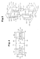
- a fuse 11 and a fuse support, or fuse box 19, according to a first embodiment of the present invention will now be described with reference to Figs. 1 to 5.
- like numerals are used for like elements throughout.
- the fuse box 19, which is used in a 42V system, includes a frame 19a and a cover 19b.
- a fuse compartment 27 is defined in the frame 19a.
- Pairs of guide blocks 21 (only one pair shown) are arranged in the frame 19a.
- a blade fuse (42V fuse) 11 is fitted between each pair of guide blocks 21.
- the 42V fuse 11 has an input terminal 12, an output terminal 13, a fuse line 14, which connects the two terminals 12, 13, and a housing 15, which covers the fuse line 14.
- the housing 15 has a thin profile and is preferably made of a heat resistant and transparent synthetic resin.
- the housing 15 includes a plate-like head 15d and a body 15c, which is formed integrally with the head 15d.
- An internal space is defined in the body 15c.
- the internal space includes terminal receptacles 15a and a fuse line receptacle 15b.
- the fuse line receptacle 15b receives the fuse line 14.
- the input terminal 12 and the output terminal 13 respectively have basal ends 12a, 13a, which are fixed to the corresponding terminal receptacles 15a, and distal ends 12b, 13b, which project from the housing 15.
- the distal ends 12b, 13b each have a substantially uniform thickness.
- the width S1 of the terminals 12, 13 is 2.8 ⁇ 0.2mm to comply with automobile industry standards.
- Each of the distal ends 12b, 13b has a tapered portion 17. The remaining part of each of the distal ends 12b, 13b is straight.
- Each tapered portion 17 becomes narrower as the distance from the basal ends 12a, 13a increases.
- the curved fuse line 14 connects the basal end 12a of the input terminal 12 with the basal end 12a of the output terminal 13.
- the input terminal 12, the output terminal 13, and the fuse line 14 are formed integrally by punching a metal sheet.
- the body 15c has relatively wide front and rear walls 30, 31 and relatively narrow right and left walls 32, 33.
- the front and rear walls 30, 31 each have two stepped portions 18 and a thin projection 26 located between the stepped portions 18.
- Each stepped portion 18 is flat and extends in the longitudinal direction of the input and output terminals 12, 13.
- the thickness u1 of the body 15c at where the projection 26 (thick portion) is located is about four millimeters to comply with automobile industry standards.
- the thickness t1 of the body 15c where each stepped portion 18 is located is less than the thickness u1 of the thick portion.
- the input terminal 12 and the output terminal 13 are each fitted into a socket 20, which extends into the 42V fuse box 19.
- Each socket 20 accommodates an electrode 23 (Fig. 2) connected to a battery and an electric device (neither shown).
- the input terminal 12 and the output terminal 13 are electrically connected to the associated electrode 23.
- the battery has the capability to supply 42V and to store 32V.
- the guide blocks 21 are formed to surround an opening 20a of each socket 20.
- a guide groove 22 extends through each guide block 21.
- the width t2 of the guide groove 22 is substantially the same as the thickness t1 of the housing 15 at the stepped portion 18.
- the opposing pair of guide blocks 21 supports the 42V fuse 11.
- the 14V fuse 111 has an input terminal 112 and an output terminal 113. Basal ends of the input and output terminals 112, 113 are accommodated in a housing 115.
- the housing 115 has a body 115c with a front wall 30 and a rear wall 31, each of which includes a thin projection 126, two side walls 125, and two channels 124.
- the channels 124 extend in the longitudinal direction of the input and output terminals 112, 113.
- the thickness dl of the body 15c where each side wall 125 is formed is about four millimeters to comply with automobile industry standards. Thus, the width dl of the side walls 125 is substantially the same as the thickness ul at the thick portion of the 42V fuse 11.
- Pairs of guide blocks 121 (only one pair shown) for the 14V fuses 111 are formed on a 14V fuse box 119.
- a guide groove 122 extends along each guide block 121.
- the width d2 of the guide groove 122 is substantially the same as the width dl of the side walls 125.
- the width s2 of the input and output terminals 112, 113 is 2.8 ⁇ 0.2mm.
- the dimensions of the other parts of the 14V fuse 111 are substantially the same as the corresponding parts of the 42V fuse 11.
- the electric characteristics of the 42V fuse and the 14V fuse 111 will now be discussed.
- the rated voltage of the 42V fuse 11 is 55V and the breaking characteristic of the 42V fuse is 55V ⁇ 1000A (rated voltage ⁇ rated breaking current).
- the fusion time of the 14V fuse 111 is substantially the same as that of the 42V fuse 11. The fusion time refers to the time required for the fuse line 14 to melt when an excessive current, which is greater than a predetermined current value, flows through the fuse line 14.
- the fuse line 14 is capable of withstanding a current corresponding to 110% of the rated current for over 100 hours.
- the fuse line 14 melts within 0.75 to 1,800 seconds when a current corresponding to 135% of the rated current flows through the fuse line 14.
- the fuse line 14 melts within 0.15 to 5 seconds when a current corresponding to 200% of the rated current flows through the fuse line 14.
- the fuse line 14 melts within 0.04 to 0.5 seconds when a current corresponding to 350% of the rated current flows through the fuse line 14.
- the fuse line 14 melts within 0.02 to 0.2 seconds when a current corresponding to 600% of the rated current flows through the fuse line 14.
- the connection of the 42V fuse 11 to the 42V fuse box 19 will now be discussed.
- the stepped portions 18 (narrow portions) of the 42V fuse 11 are each engaged with the guide groove 22 of the corresponding guide block 21.
- the 42V fuse 11 is moved along the guide grooves 22 until the distal ends 12b, 13b are fit into the associated sockets 20. This connects the distal ends 12b, 13b to the electrodes 23.
- the guide grooves 22 serve to facilitate the connection of the 42V fuse 11. Further, the connected 42V fuse 11 is supported by the guide block 21, which prevents the 42V fuse 11 from falling.
- the guide blocks 21 prevent the connection of the 14V fuse 111. This prevents the 14V fuse 111 from being inadvertently connected to the 42V fuse box 19.
- the 42V fuse 11 may be connected to the 14V fuse box 119.
- the width d2 of the guide grooves 122 of the guide blocks 121 is greater than the thickness t1 of the narrow portion of the 42V fuse 11. This permits the 42V fuse 11 to be received by the pair of the guide blocks 121.
- the 42V fuse 11 and the 14V fuse 111 are formed so that the terminal widths s1, s2, the terminal thickness, and the distance between the terminals 12, 13 and 112, 113 comply with the same standard.
- the 42V fuse 11 may easily be inserted into the sockets 120 and connected with electrodes (not shown) of the 14V system.
- the 42V fuse 11 is used in lieu of the 14V fuse 111, excessive current melts the fuse line 14 of the 42V fuse 11 within a predetermined time. Thus, the employment of the 42V fuse 11 does not cause problems. Further, since the rated voltage of the 42V fuse 11 is greater than the voltage of the 14V system, an arc is not formed when the 42V fuse 11 is being used.
- the first embodiment has the advantages described below.
- the guide blocks 21 shown in Fig. 1b may be arranged about the sockets 20 of Fig. 6. This facilitates the connection of the 42V fuse 11 to the sockets 20 and prevents the connected 42V fuse 11 from falling.
- the guide blocks 121 of Fig. 5 may be arranged about the sockets 20 of Fig. 6, and the side walls 125 of the 14V fuse 111 may be formed on the 42V fuse 11. In such case, the relatively small sockets 20 prevent the connection of the 14V fuse 111. Further, a common housing may be used for the 42V fuse 11 and the 14V fuse 111.
- the rated voltage of the 42V fuse 11 does not have to be 55V as long as it is higher than 42V, such as 50V or 45V.
- the width s1 of the stepped portions 18 may be narrower or wider as long as the left and right walls 32, 33 have the width s1.
- the projection 26 of the 42V fuse may be eliminated.
- the front and rear walls 30, 31 of the housing 15 may be flat, and the body 15c may have a uniform thickness u1, which is equal to the thickness t1 of the narrow portion.
Landscapes
- Fuses (AREA)
Abstract
Description
Claims (25)
- A fuse (11) having two substantially parallel terminals (12, 13), wherein each terminal has a distal end and a basal end, and wherein the terminals lie in an imaginary plane; and a fuse line (14) connecting the two terminals, the fuse being characterized by a housing (15) for accommodating the basal ends of the two terminals and the fuse line, wherein the housing includes:a front surface (18);a rear surface (18), which is generally parallel to and spaced from the front surface, wherein the thickness (t1) of the fuse, as measured in a direction that is perpendicular to the imaginary plane, is substantially less than four millimeters at a location that includes at least one lateral edge of the fuse such that the at least one lateral edge fits within a fuse guide (21) that has a matching dimension.
- The fuse according to claim 1, wherein the housing has a first side surface (32) and a second side surface (33), the second side surface being opposite to the first side surface, wherein the side surfaces connect the front surface to the rear surface at opposite sides of the fuse, respectively.
- The fuse according to claim 2, wherein the side surfaces are parallel.
- The fuse according to claim 3, wherein a dimension of the side surfaces that is measured in a direction perpendicular to the imaginary plane is equal to the thickness of the fuse.
- The fuse according to claim 1, wherein the front surface includes a central front projection (26), and the rear surface includes a central rear projection (26), and the thickness (u1) of the fuse is approximately four millimeters at a central part of the fuse that corresponds to the projections.
- The fuse according to claim 5, wherein the housing includes a head (15d) at the top of the fuse, wherein the head connects the front surface to the rear surface.
- The fuse according to claim 1, wherein the location that includes at least one lateral edge of the fuse has no projections.
- The fuse according to claim 1, wherein the fuse is a 42 volt blade fuse for use in an electric circuit of a vehicle.
- A fuse (11) having two substantially parallel terminals (12, 13), wherein each terminal has a distal end and a basal end, and wherein the terminals lie in an imaginary plane; a fuse line (14) connecting the two terminals; and a housing (15) for accommodating the basal ends of the two terminals and the fuse line, the fuse being characterized in that the width (S1) of at least one of the terminals, as measured in a lateral direction along the imaginary plane, is substantially less than 2.8 millimeters.
- The fuse according to claim 9, wherein the fuse is a 42 volt blade fuse for use in an electric circuit of a vehicle.
- A fuse support (19) for accommodating a first fuse (11) and for blocking a second fuse (111), wherein the first fuse is rated at a first voltage (42V) and the second fuse is rated at a second voltage (14V), wherein the first voltage is higher than the second voltage, the fuse support characterized by a restriction member (20, 21) for preventing reception of the second fuse in the fuse support.
- The fuse support according to claim 11, wherein a certain dimension (t1, S1) of the first fuse is smaller than a corresponding dimension (d1, S2) of the second fuse, and the restriction member is located at a position that corresponds to the location of the smaller dimension of the first fuse.
- The fuse support according to claim 12, wherein each of the first and second fuses includes two substantially parallel terminals, each terminal having a distal end and a basal end, and wherein the terminals lie in an imaginary plane, a fuse line connecting the two terminals, and a housing for accommodating the basal ends of the two terminals and the fuse line, wherein the housing includes a front surface and a rear surface, the rear surface being generally parallel to and spaced from the front surface, wherein the thickness (t1) of the first fuse, as measured in a direction that is perpendicular to the imaginary plane, is substantially less than four millimeters at a location that includes at least one lateral edge of the first fuse, and the corresponding thickness (d1) of the second fuse is substantially four millimeters, wherein the restriction member includes a pair of guide blocks (21) for guiding the first fuse, and wherein at least one of the guide blocks includes a fuse guide groove (22) having a dimension (t2) that is substantially equal to the thickness of the first fuse.
- The fuse support according to claim 12, wherein the first fuse includes a first terminal, which has a lateral dimension, and the second fuse includes a corresponding first terminal that has a corresponding lateral dimension, wherein the lateral dimension of the first terminal of the first fuse is smaller than that of the second fuse, and wherein the restriction member includes a socket (20) to receive the first terminal, the socket being too small to receive the first terminal of the second fuse.
- The fuse support according to claim 12, wherein the first fuse is a 42V blade fuse for use in an electric circuit of a vehicle and the second fuse is a 14V blade fuse.
- A circuit protection assembly (11, 19) for accommodating a first fuse (11) and for blocking a second fuse (111), wherein the first fuse is rated at a first voltage (42V) and the second fuse is rated at a second voltage (14V), the first voltage being higher than the second voltage, the assembly characterized by:the first fuse (11), wherein the first fuse includes:two substantially parallel terminals, wherein each terminal has a distal end and a basal end, and wherein the terminals lie in an imaginary plane;a fuse line connecting the two terminals; anda housing for accommodating the basal ends of the two terminals and the fuse line, wherein the housing includes:a front surface; anda rear surface, which is generally parallel to and spaced from the front surface, wherein the thickness (t1) of the fuse, as measured in a direction that is perpendicular to the imaginary plane, is substantially less than four millimeters at a location that includes at least one lateral edge of the fuse;a support (19) for receiving the first fuse, wherein the support includes a restriction member (20, 21) for permitting the connection of the first fuse and for blocking the second fuse, the restriction member including a pair of guide blocks (21) for guiding the first fuse, and wherein at least one of the guide blocks has a guide groove (22), one dimension (t2) of which is substantially equal to the thickness of the first fuse.
- The circuit protection assembly according to claim 16, wherein the first fuse is a 42V blade fuse for use in an electric circuit of a vehicle and the second fuse is a 14V blade fuse.
- A circuit protection assembly (11, 19) for accommodating a first fuse (11) and for blocking a second fuse (111), wherein the first fuse is rated at a first voltage (42V) and the second fuse is rated at a second voltage (14V), the first voltage being higher than the second voltage, the assembly characterized by:
the first fuse, wherein the first fuse includes:two substantially parallel terminals (12, 13), wherein each terminal has a distal end and a basal end, and the terminals lie in an imaginary plane, andwherein the width (S1) of one terminal, as measured in a lateral direction along the imaginary plane, is substantially less than 2.8 millimeters;a fuse line (14) connecting the two terminals; anda housing (15) for accommodating the basal ends of the terminals and the fuse line;a socket (20) for receiving one of the terminals of the first fuse, wherein the socket has a dimension that is substantially the same as the width (S1) of the one terminal of the first fuse. - The circuit protection assembly according to claim 18, wherein the first fuse is a 42V blade fuse for use in a vehicle electric circuit system that generates 42V and stores 32V and the second fuse is a 14V blade fuse for use in a vehicle electric circuit system that generates 14V and stores 12V.
- A first fuse (11), which can replace a second fuse (111), wherein the first fuse is rated at a higher voltage than the second fuse, and a certain dimension (t1) of the first fuse is smaller than a corresponding dimension (d1, S2) of the second fuse, the first fuse characterized by:two substantially parallel terminals (12, 13), wherein each terminal has a distal end and a basal end, and wherein the terminals lie in an imaginary plane;a fuse line (14) connecting the two terminals; anda housing (15) for accommodating the basal ends of the terminals and the fuse line, wherein the housing includes:a front surface (18); anda rear surface (18) generally parallel to and spaced from the front surface, wherein the first housing has a thickness (t1), as measured in a direction that is perpendicular to the imaginary plane at a location that includes at least one lateral edge of the first fuse, that is substantially smaller than a corresponding thickness (d1) of the second fuse.
- The first fuse according to claim 20, wherein the first fuse is a 42V blade fuse for use in a vehicle electric circuit system that generates 42V and stores 32V, and the second fuse is a 14V blade fuse for use in a vehicle electric circuit system that generates 14V and stores 12V.
- The first fuse according to claim 20, wherein the front surface includes a central front projection (26), and the rear surface includes a central rear projection (26), and the thickness (u1) of the first fuse is approximately four millimeters at a central part of the fuse that corresponds to the projections.
- The first fuse according to claim 22, wherein the housing includes a head (15d) at the top of the first fuse, wherein the head connects the front surface to the rear surface.
- A first fuse (11), which can replace a second fuse (111), wherein the first fuse is rated at a higher voltage than the second fuse, and a certain dimension (S1) of the first fuse is smaller than a corresponding dimension of the second fuse, the first fuse characterized by:two substantially parallel terminals (12, 13), wherein each terminal has a distal end and a basal end, and wherein the terminals lie in an imaginary plane;a fuse line (14) connecting the two terminals; anda housing (15) for accommodating the basal ends of the two terminals and the fuse line, and wherein the width (S1) of at least one of the terminals, as measured in a lateral direction along the imaginary plane of the at least one of the terminals, is substantially smaller than a corresponding width (S2) of the second fuse.
- The first fuse according to claim 24, wherein the first fuse is a 42V blade fuse for use in a vehicle electric circuit system that generates 42V and stores 32V, and the second fuse is a 14V blade fuse for use in a vehicle electric circuit system that generates 14V and stores 12V.
Applications Claiming Priority (2)
| Application Number | Priority Date | Filing Date | Title |
|---|---|---|---|
| JP2000058691A JP2001250466A (en) | 2000-03-03 | 2000-03-03 | Fuse element and fuse mounting device |
| JP2000058691 | 2000-03-03 |
Publications (3)
| Publication Number | Publication Date |
|---|---|
| EP1130616A2 true EP1130616A2 (en) | 2001-09-05 |
| EP1130616A3 EP1130616A3 (en) | 2003-02-05 |
| EP1130616B1 EP1130616B1 (en) | 2016-08-31 |
Family
ID=18579252
Family Applications (1)
| Application Number | Title | Priority Date | Filing Date |
|---|---|---|---|
| EP01850041.3A Expired - Lifetime EP1130616B1 (en) | 2000-03-03 | 2001-03-01 | Fuse and fuse support |
Country Status (11)
| Country | Link |
|---|---|
| US (1) | US6608546B2 (en) |
| EP (1) | EP1130616B1 (en) |
| JP (1) | JP2001250466A (en) |
| KR (1) | KR100567727B1 (en) |
| CN (1) | CN1244120C (en) |
| BR (1) | BR0100815A (en) |
| CA (1) | CA2339394A1 (en) |
| HK (1) | HK1039399B (en) |
| MY (1) | MY126123A (en) |
| RU (1) | RU2222071C2 (en) |
| TW (1) | TW502272B (en) |
Cited By (1)
| Publication number | Priority date | Publication date | Assignee | Title |
|---|---|---|---|---|
| WO2005013307A1 (en) * | 2003-07-31 | 2005-02-10 | Yazaki Corporation | Fuse cavity and electric junction box equipped therewith |
Families Citing this family (26)
| Publication number | Priority date | Publication date | Assignee | Title |
|---|---|---|---|---|
| CN1260297C (en) * | 2001-08-07 | 2006-06-21 | 太平洋精工株式会社 | Polyamide resin composition for fuse elements, and fuse element |
| JP2004032839A (en) * | 2002-06-21 | 2004-01-29 | Sumitomo Wiring Syst Ltd | Electric junction box |
| JP2004206910A (en) * | 2002-12-24 | 2004-07-22 | Sumitomo Wiring Syst Ltd | Fuse connector |
| JP4001835B2 (en) * | 2003-04-04 | 2007-10-31 | 矢崎総業株式会社 | Fuse cavity structure and electrical junction box |
| US6781503B1 (en) * | 2003-04-24 | 2004-08-24 | Yazaki Corporation | Fuse assembly for differently structured fuses |
| US7825766B2 (en) * | 2008-07-25 | 2010-11-02 | Cooper Technologies Company | Touch safe fuse module with ampacity rejection |
| DE20319350U1 (en) * | 2003-12-13 | 2004-03-04 | Wilhelm Pudenz Gmbh | Fuse insert with flat insulating body |
| DE10358444A1 (en) * | 2003-12-13 | 2005-07-07 | Wilhelm Pudenz Gmbh | One-piece fuse-link, method for producing the one-piece fuse-link and device for carrying out the method |
| JP2005353465A (en) * | 2004-06-11 | 2005-12-22 | Sumitomo Wiring Syst Ltd | Fusible link mounting structure of electric connection box |
| CN101079355B (en) * | 2005-06-20 | 2012-04-25 | 力特保险丝有限公司 | Water resistant in-line fuse holder |
| KR100757576B1 (en) * | 2006-07-10 | 2007-09-10 | 현대자동차주식회사 | Junction box for vehicle with fuse structure of dual power system |
| US8063646B2 (en) * | 2006-08-23 | 2011-11-22 | Micron Technology, Inc. | Apparatus and methods for testing microelectronic devices |
| JP5187941B2 (en) * | 2008-01-23 | 2013-04-24 | 矢崎総業株式会社 | Electrical junction box |
| IT1394694B1 (en) * | 2009-04-17 | 2012-07-13 | Palazzoli Spa | FUSE HOLDER DEVICE, PARTICULARLY FOR INTERLOCKED SOCKETS AND ELECTRIC APPLIANCES IN GENERAL |
| JP5422429B2 (en) * | 2010-02-10 | 2014-02-19 | 矢崎総業株式会社 | Fuse unit |
| CN103380477B (en) * | 2011-02-18 | 2016-01-13 | 矢崎总业株式会社 | Fuse and fuse attachment structure |
| JP5923076B2 (en) * | 2013-10-15 | 2016-05-24 | 太平洋精工株式会社 | Fuse, fuse box, and fuse device |
| JP1515917S (en) * | 2014-05-12 | 2015-01-26 | ||
| JP2016091624A (en) * | 2014-10-30 | 2016-05-23 | 太平洋精工株式会社 | Housing, fuse, and fuse box attached to a multi-pole fusible link |
| US9824842B2 (en) * | 2015-01-22 | 2017-11-21 | Littelfuse, Inc. | Wire in air split fuse with built-in arc quencher |
| CN105006411B (en) * | 2015-08-19 | 2017-07-28 | 安徽江淮汽车集团股份有限公司 | A kind of fuse attachment structure |
| CN105225901B (en) * | 2015-11-06 | 2017-06-06 | 安徽江淮汽车集团股份有限公司 | A kind of fuse attachment structure and diagnosis interface protector |
| CN106548903A (en) * | 2017-01-19 | 2017-03-29 | 上海长园维安电子线路保护有限公司 | Combination type can be through reflow soldering temperature fuse |
| JP1621077S (en) * | 2018-06-04 | 2018-12-25 | ||
| DE102019122611A1 (en) * | 2019-08-22 | 2021-02-25 | Endress+Hauser SE+Co. KG | SMD-solderable component and method for producing an SMD-solderable component |
| JP7049634B1 (en) * | 2020-12-04 | 2022-04-07 | 株式会社オートネットワーク技術研究所 | Fuse and in-vehicle equipment |
Family Cites Families (19)
| Publication number | Priority date | Publication date | Assignee | Title |
|---|---|---|---|---|
| CH38173A (en) | 1906-07-28 | 1907-09-15 | Werner Menzel | Set of fuses for various currents and voltages, the inserts of which cannot be confused |
| DE475943C (en) | 1925-03-09 | 1929-05-06 | Charles Joseph Levy Genannt Le | Unmistakable fuse with hidden contacts |
| GB621316A (en) | 1947-02-18 | 1949-04-07 | Wm Sanders And Co Wednesbury L | Improvements relating to electrical fuses |
| GB677648A (en) | 1949-08-15 | 1952-08-20 | Wm Sanders & Co Wednesbury Ltd | Improvements relating to electrical fuses |
| US3909767A (en) * | 1974-01-14 | 1975-09-30 | Littelfuse Inc | Miniature plug-in fuse |
| DE2722008A1 (en) | 1977-05-14 | 1978-11-16 | Kromberg & Schubert | Fused plug for protecting electrical circuit - has transparent window for observing or indicating condition of fusible element |
| US4164726A (en) | 1977-08-01 | 1979-08-14 | Weibe Gerald L | Encapsulated plug-in electrically conducting component |
| US4224592A (en) * | 1978-04-03 | 1980-09-23 | Mcgraw-Edison Company | Miniature plug-in fuse assembly and method of manufacture |
| US4499447A (en) * | 1983-06-17 | 1985-02-12 | Guim Multi-Tech Corporation | Blade terminal fuses with integrity indicator |
| JPH0720828Y2 (en) | 1989-06-14 | 1995-05-15 | エス・オー・シー株式会社 | Ultra-small current fuse |
| JP2563311Y2 (en) * | 1990-09-12 | 1998-02-18 | 矢崎総業株式会社 | Fuse box |
| US5179503A (en) * | 1991-04-19 | 1993-01-12 | United Technologies Automotive, Inc. | Modular automobile power distribution box |
| JP2778856B2 (en) * | 1991-07-10 | 1998-07-23 | 住友電装株式会社 | Small junction box |
| WO1996013847A1 (en) | 1994-10-28 | 1996-05-09 | Cooper Industries, Inc. | Remote alarm fuse |
| DE69520424T2 (en) * | 1995-01-10 | 2001-11-15 | Sumitomo Wiring Systems, Ltd. | Junction box |
| KR19980039754U (en) * | 1996-12-20 | 1998-09-15 | 양재신 | Automotive fuse |
| DE19705242A1 (en) | 1997-02-12 | 1998-08-13 | Wilhelm Pudenz Gmbh Elektrotec | High voltage vehicle fuse used e.g. for floor guided vehicles |
| JP2000011850A (en) | 1998-06-24 | 2000-01-14 | Sumitomo Wiring Syst Ltd | Fuse and erroneous fitting prevention structure of the fuse to fuse box |
| RU12287U1 (en) * | 1999-08-12 | 1999-12-16 | Открытое акционерное общество "Автоэлектроарматура" (АО "АВАР") | FUSION CAR FUSE |
-
2000
- 2000-03-03 JP JP2000058691A patent/JP2001250466A/en active Pending
-
2001
- 2001-02-26 US US09/794,196 patent/US6608546B2/en not_active Expired - Lifetime
- 2001-02-28 CA CA002339394A patent/CA2339394A1/en not_active Abandoned
- 2001-02-28 KR KR1020010010378A patent/KR100567727B1/en not_active Expired - Lifetime
- 2001-03-01 TW TW090104730A patent/TW502272B/en not_active IP Right Cessation
- 2001-03-01 EP EP01850041.3A patent/EP1130616B1/en not_active Expired - Lifetime
- 2001-03-02 RU RU2001105901/09A patent/RU2222071C2/en not_active IP Right Cessation
- 2001-03-02 MY MYPI20010970A patent/MY126123A/en unknown
- 2001-03-02 BR BR0100815-3A patent/BR0100815A/en not_active Application Discontinuation
- 2001-03-02 CN CNB011093811A patent/CN1244120C/en not_active Expired - Lifetime
-
2002
- 2002-02-07 HK HK02100981.9A patent/HK1039399B/en not_active IP Right Cessation
Cited By (3)
| Publication number | Priority date | Publication date | Assignee | Title |
|---|---|---|---|---|
| WO2005013307A1 (en) * | 2003-07-31 | 2005-02-10 | Yazaki Corporation | Fuse cavity and electric junction box equipped therewith |
| US7232342B2 (en) | 2003-07-31 | 2007-06-19 | Yazaki Corporation | Fuse cavity and electric junction box equipped therewith |
| CN1830050B (en) * | 2003-07-31 | 2011-06-15 | 矢崎总业株式会社 | Fuse cavity and electric junction box equipped therewith |
Also Published As
| Publication number | Publication date |
|---|---|
| RU2222071C2 (en) | 2004-01-20 |
| CN1311517A (en) | 2001-09-05 |
| BR0100815A (en) | 2001-11-06 |
| KR20010087234A (en) | 2001-09-15 |
| MY126123A (en) | 2006-09-29 |
| CN1244120C (en) | 2006-03-01 |
| HK1039399A1 (en) | 2002-04-19 |
| HK1039399B (en) | 2006-09-08 |
| EP1130616B1 (en) | 2016-08-31 |
| US20020044038A1 (en) | 2002-04-18 |
| TW502272B (en) | 2002-09-11 |
| KR100567727B1 (en) | 2006-04-04 |
| JP2001250466A (en) | 2001-09-14 |
| US6608546B2 (en) | 2003-08-19 |
| EP1130616A3 (en) | 2003-02-05 |
| CA2339394A1 (en) | 2001-09-03 |
Similar Documents
| Publication | Publication Date | Title |
|---|---|---|
| EP1130616B1 (en) | Fuse and fuse support | |
| EP1139373B1 (en) | Fuse block | |
| US20080061920A1 (en) | Fuse cavity structure and electric connection box | |
| EP1336978B1 (en) | Blade fuse | |
| US4884050A (en) | Blade terminal tap fuse | |
| US6830482B2 (en) | Fusible link and method of producing said fusible link | |
| US7292130B2 (en) | Fusible link and battery fuse unit containing the fusible link | |
| JP2004127703A (en) | Fusible link unit | |
| JP2002369336A (en) | Electrical junction box | |
| US7612647B2 (en) | Fusible link | |
| WO2006047231A2 (en) | Fuse linked relay | |
| US6734780B2 (en) | Fuse assembly | |
| EP1498927B1 (en) | An improved high-current protection device | |
| US20020024414A1 (en) | Fuse and fuse-mounting electric connection box | |
| US20260058083A1 (en) | Fusible link unit and electric junction box | |
| CN100593890C (en) | Fuse cavity structure and electric connection box | |
| KR102644817B1 (en) | Fuse, and method of manufacturing the fuse | |
| EP1548786B1 (en) | Fuse connection structure of bus bar and electric connection box provided with same | |
| EP4654241A1 (en) | Fuse holder device for high-power electrical circuit | |
| WO2024127804A1 (en) | Fuse | |
| JP2004311289A (en) | Fuse cavity structure and electrical junction box | |
| KR19980028886A (en) | Junction block combination for vehicle |
Legal Events
| Date | Code | Title | Description |
|---|---|---|---|
| PUAI | Public reference made under article 153(3) epc to a published international application that has entered the european phase |
Free format text: ORIGINAL CODE: 0009012 |
|
| AK | Designated contracting states |
Kind code of ref document: A2 Designated state(s): AT BE CH CY DE DK ES FI FR GB GR IE IT LI LU MC NL PT SE TR |
|
| AX | Request for extension of the european patent |
Free format text: AL;LT;LV;MK;RO;SI |
|
| PUAL | Search report despatched |
Free format text: ORIGINAL CODE: 0009013 |
|
| AK | Designated contracting states |
Designated state(s): AT BE CH CY DE DK ES FI FR GB GR IE IT LI LU MC NL PT SE TR |
|
| AX | Request for extension of the european patent |
Extension state: AL LT LV MK RO SI |
|
| 17P | Request for examination filed |
Effective date: 20030721 |
|
| AKX | Designation fees paid |
Designated state(s): DE ES FR GB IT SE |
|
| 17Q | First examination report despatched |
Effective date: 20060623 |
|
| GRAP | Despatch of communication of intention to grant a patent |
Free format text: ORIGINAL CODE: EPIDOSNIGR1 |
|
| INTG | Intention to grant announced |
Effective date: 20160404 |
|
| RIN1 | Information on inventor provided before grant (corrected) |
Inventor name: ANDOH, HIDEKI Inventor name: SHIMIZU, AKIHIKO |
|
| GRAS | Grant fee paid |
Free format text: ORIGINAL CODE: EPIDOSNIGR3 |
|
| GRAA | (expected) grant |
Free format text: ORIGINAL CODE: 0009210 |
|
| AK | Designated contracting states |
Kind code of ref document: B1 Designated state(s): DE ES FR GB IT SE |
|
| REG | Reference to a national code |
Ref country code: GB Ref legal event code: FG4D |
|
| REG | Reference to a national code |
Ref country code: DE Ref legal event code: R096 Ref document number: 60150085 Country of ref document: DE |
|
| PG25 | Lapsed in a contracting state [announced via postgrant information from national office to epo] |
Ref country code: ES Free format text: LAPSE BECAUSE OF FAILURE TO SUBMIT A TRANSLATION OF THE DESCRIPTION OR TO PAY THE FEE WITHIN THE PRESCRIBED TIME-LIMIT Effective date: 20160831 Ref country code: SE Free format text: LAPSE BECAUSE OF FAILURE TO SUBMIT A TRANSLATION OF THE DESCRIPTION OR TO PAY THE FEE WITHIN THE PRESCRIBED TIME-LIMIT Effective date: 20160831 |
|
| REG | Reference to a national code |
Ref country code: FR Ref legal event code: PLFP Year of fee payment: 17 |
|
| REG | Reference to a national code |
Ref country code: DE Ref legal event code: R097 Ref document number: 60150085 Country of ref document: DE |
|
| PLBE | No opposition filed within time limit |
Free format text: ORIGINAL CODE: 0009261 |
|
| STAA | Information on the status of an ep patent application or granted ep patent |
Free format text: STATUS: NO OPPOSITION FILED WITHIN TIME LIMIT |
|
| 26N | No opposition filed |
Effective date: 20170601 |
|
| GBPC | Gb: european patent ceased through non-payment of renewal fee |
Effective date: 20170301 |
|
| PG25 | Lapsed in a contracting state [announced via postgrant information from national office to epo] |
Ref country code: GB Free format text: LAPSE BECAUSE OF NON-PAYMENT OF DUE FEES Effective date: 20170301 |
|
| REG | Reference to a national code |
Ref country code: FR Ref legal event code: PLFP Year of fee payment: 18 |
|
| PGFP | Annual fee paid to national office [announced via postgrant information from national office to epo] |
Ref country code: DE Payment date: 20200218 Year of fee payment: 20 Ref country code: IT Payment date: 20200221 Year of fee payment: 20 |
|
| PGFP | Annual fee paid to national office [announced via postgrant information from national office to epo] |
Ref country code: FR Payment date: 20200214 Year of fee payment: 20 |
|
| REG | Reference to a national code |
Ref country code: DE Ref legal event code: R071 Ref document number: 60150085 Country of ref document: DE |