EP1130530A2 - Part marking method applicable to industrial parts - Google Patents
Part marking method applicable to industrial parts Download PDFInfo
- Publication number
- EP1130530A2 EP1130530A2 EP01301690A EP01301690A EP1130530A2 EP 1130530 A2 EP1130530 A2 EP 1130530A2 EP 01301690 A EP01301690 A EP 01301690A EP 01301690 A EP01301690 A EP 01301690A EP 1130530 A2 EP1130530 A2 EP 1130530A2
- Authority
- EP
- European Patent Office
- Prior art keywords
- coherent
- clause
- detecting
- alterations
- coherent pattern
- Prior art date
- Legal status (The legal status is an assumption and is not a legal conclusion. Google has not performed a legal analysis and makes no representation as to the accuracy of the status listed.)
- Withdrawn
Links
Images
Classifications
-
- G—PHYSICS
- G06—COMPUTING OR CALCULATING; COUNTING
- G06K—GRAPHICAL DATA READING; PRESENTATION OF DATA; RECORD CARRIERS; HANDLING RECORD CARRIERS
- G06K19/00—Record carriers for use with machines and with at least a part designed to carry digital markings
- G06K19/06—Record carriers for use with machines and with at least a part designed to carry digital markings characterised by the kind of the digital marking, e.g. shape, nature, code
- G06K19/06009—Record carriers for use with machines and with at least a part designed to carry digital markings characterised by the kind of the digital marking, e.g. shape, nature, code with optically detectable marking
- G06K19/06018—Record carriers for use with machines and with at least a part designed to carry digital markings characterised by the kind of the digital marking, e.g. shape, nature, code with optically detectable marking one-dimensional coding
-
- G—PHYSICS
- G06—COMPUTING OR CALCULATING; COUNTING
- G06K—GRAPHICAL DATA READING; PRESENTATION OF DATA; RECORD CARRIERS; HANDLING RECORD CARRIERS
- G06K1/00—Methods or arrangements for marking the record carrier in digital fashion
- G06K1/12—Methods or arrangements for marking the record carrier in digital fashion otherwise than by punching
- G06K1/126—Methods or arrangements for marking the record carrier in digital fashion otherwise than by punching by photographic or thermographic registration
-
- G—PHYSICS
- G06—COMPUTING OR CALCULATING; COUNTING
- G06K—GRAPHICAL DATA READING; PRESENTATION OF DATA; RECORD CARRIERS; HANDLING RECORD CARRIERS
- G06K7/00—Methods or arrangements for sensing record carriers, e.g. for reading patterns
- G06K7/01—Details
- G06K7/016—Synchronisation of sensing process
- G06K7/0163—Synchronisation of sensing process by means of additional timing marks on the record-carrier
-
- C—CHEMISTRY; METALLURGY
- C21—METALLURGY OF IRON
- C21D—MODIFYING THE PHYSICAL STRUCTURE OF FERROUS METALS; GENERAL DEVICES FOR HEAT TREATMENT OF FERROUS OR NON-FERROUS METALS OR ALLOYS; MAKING METAL MALLEABLE, e.g. BY DECARBURISATION OR TEMPERING
- C21D10/00—Modifying the physical properties by methods other than heat treatment or deformation
-
- C—CHEMISTRY; METALLURGY
- C21—METALLURGY OF IRON
- C21D—MODIFYING THE PHYSICAL STRUCTURE OF FERROUS METALS; GENERAL DEVICES FOR HEAT TREATMENT OF FERROUS OR NON-FERROUS METALS OR ALLOYS; MAKING METAL MALLEABLE, e.g. BY DECARBURISATION OR TEMPERING
- C21D10/00—Modifying the physical properties by methods other than heat treatment or deformation
- C21D10/005—Modifying the physical properties by methods other than heat treatment or deformation by laser shock processing
-
- C—CHEMISTRY; METALLURGY
- C21—METALLURGY OF IRON
- C21D—MODIFYING THE PHYSICAL STRUCTURE OF FERROUS METALS; GENERAL DEVICES FOR HEAT TREATMENT OF FERROUS OR NON-FERROUS METALS OR ALLOYS; MAKING METAL MALLEABLE, e.g. BY DECARBURISATION OR TEMPERING
- C21D2221/00—Treating localised areas of an article
-
- G—PHYSICS
- G06—COMPUTING OR CALCULATING; COUNTING
- G06K—GRAPHICAL DATA READING; PRESENTATION OF DATA; RECORD CARRIERS; HANDLING RECORD CARRIERS
- G06K19/00—Record carriers for use with machines and with at least a part designed to carry digital markings
- G06K19/06—Record carriers for use with machines and with at least a part designed to carry digital markings characterised by the kind of the digital marking, e.g. shape, nature, code
- G06K2019/06215—Aspects not covered by other subgroups
- G06K2019/06271—Relief-type marking
Definitions
- the present invention relates to the marking of industrial parts.
- the invention relates to permanent marking of parts used in hostile environments and where physical alteration of the part to create the mark can be detrimental.
- markings are permanent, able to withstand usage (e.g., surface abrasion), able to withstand thermal cycling, able to withstand harsh environments during use and servicing, and, most importantly, have no impact on the function and lifespan of the part.
- Certain parts additionally require that their mechanical design not be compromised by the creation of markings upon the surface of the finished part.
- the removal/displacement of a part's material can affect the function of a system (weight distribution and balance can be affected) or can endanger the part itself (stamped lettering can act as an initiation site for stress cracking).
- Part marks can be of two types: human readable and non-human readable.
- An example of the first is a string of letters and numbers written in a particular size and font.
- An example of the latter is a supermarket barcode.
- Inks and paints have been used toidentify parts with bar-coding or simple character information. Such markings may be referred to as two-dimensional (2D) in that they substantially only affect two dimensions of the surface of the part. These methods are insufficiently permanent under the thermal environments typically encountered in aviation or power generation. Labels applied to the part surface wear off or burn off and are unsuitable for parts where the surface area is uneven or lacking sufficient area to be readable. Metallic labels are hazardous when dislodged, difficult to remark in the field, and weighty by comparison to other marking types.
- the invention disclosed herein consists of a system of modifying the physical properties of the materials comprising the surface of the part or a subsurface zone extending some depth into the material at specific localized sites using physical means that do not affect the strength related or 3D characteristics of the part material and do not rely upon painted or other 2D marking being applied to the part surface.
- a durable part marking is achieved by local surface material modification. Altering selected surface area properties of the part and placing these alterations in a coherent pattern accomplishes a method of identification marking on a part. Subsequently, the coherent pattern is detected and the coherent pattern interpreted to retrieve the original identification marking.
- the invention includes: 1) a method for surface modification, 2) a method for assuring enhanced readability and accuracy of the reading of the encoded data, and 3) a method for locating the surface alteration.
- procedures for local surface modification include:
- Shock Hardening This method, also known as “laser shock peening,” alters the surface compressive residual-stresses without changing the surface geometry to any significant degree. This is a mechanical process involving the bombardment of the surface by a localized pressure wave created by the intense pulse of laser light striking a film of water on the part surface, plastic deformation of the surface layers, and the production of a steep residual-stress field that is compressive at the surface. The slight density differential is detectable by ultrasound reflections. This is a simple and highly accurate method of surface modification.
- Ion implantation In this process, atoms of gaseous or metallic elements are ionized and pass to a high vacuum chamber where they are accelerated through a mass separator. Selected ions are then further accelerated and implanted into the target component. The implanted species occupy interstitial sites and distort the lattice. The depth of effect is very shallow, approximately 0.2 microns. Ion implantation systems utilize a focused ion beam (FIB) or micro ion beam (MIB) with a microprobe. This permits highly accurate implantation of a controlled number of ions into a target area with a high degree of aiming accuracy.
- FIB focused ion beam
- MIB micro ion beam
- the implantation of iron ions changes the magnetic characteristics of the surface. This difference in iron ions is detectable by a magnetometer.
- a small superconducting loop of one or several Josephson junctions is known as a superconducting quantum interference device (SQUID) magnetometer capable of detecting slight variations in surface magnetism.
- SQUID superconducting quantum interference device
- the implantation of doping ions changes the resistance characteristics of the surface.
- the surface resistance is defined as the electrical resistance across the surface of an object measured between the opposite sides of a square on the surface, and is expressed in ohms per square area.
- the resistivity difference caused by the dopant is also detectable by an eddy current measurement.
- a small multi-turn coil typically 1/8 inch (2.88 mm) to 1/16 inch (1.44 mm) in diameter, is positioned a short distance above and parallel to a conductive metal material.
- a sinusoidal AC current is caused to flow through the coil.
- the AC magnetic field created by the coil is coupled into the metal and causes a circular current to flow (parallel to the surface) in the metal. This is the eddy current.
- the amount of eddy current flowing and the size/shape of the current will adjust itself so that the magnetic field created by the eddy current will be exactly equal and opposite to the applied field.
- phase difference will vary depending on how the 3D conductivity of the non-ideal surface differs from what is expected from an ideal conductor. Scanning an area in this manner results in a "map" of the surface resistivity. The areas purposely altered by doping stand out clearly against the background of untreated surface area.
- Polarization The surface of the material may be polarized to place down markings and not alter the material. Reflecting a light off of the surface and detecting the reflection of coherent light from an incoherent source indicates a polarized surface. In this manner the surface can be "mapped" to recover the marking implanted.
- thermochemical diffusion treatments wherein elements including boron, nitrogen, or carbon are diffused at elevated temperatures into the interstitial regions of ferric materials. These modifications alter the material properties in a manner that, after marking, it is possible to detect that the affected zone has been processed.
- the techniques can be employed directly to "draw” or “print” a sequence of alphanumeric characters or patterns on a surface in what shall be called the “data track.”
- the string of alphanumeric characters comprising the part identification string into a sequence of digits drawn from a selected basis.
- a simple example is the 8-bit binary ASCII code digits. Binary representations are preferable since they have the highest signal-to-noise ratio when compared to other formulations. Although, base 3 and higher encoding is possible.
- the surface zone treatment pattern might be “00X0X” where "X” represents a small surface (or near surface) patch that has been “treated” using one of the above methods.
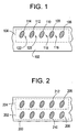
- a pictorial of the identification marking of a part 102 is generally shown in FIG. 1.
- a data track 104 is made up of a plurality of possibly treated data track areas 106 through 114.
- Each of the possibly treated data track areas 106 through 114 is either treated by one of the methods or untreated. Two or more of the surface treatment methods may be used to enhance readability.
- data track area 106 is shown treated by one method while data track area 108 is treated by another method in order to distinguish a binary encoding.
- Small intervals or spaces 116 through 122 separate adjacent possibly treated areas.
- the treated areas are be arranged serially along a straight line (1D) or a curve (2D or 3D) on a flat or curved surface or arranged in any surface appropriate 2D pattern (e.g., checkerboard patterns or radial arrangements).
- a reference track to the data track provides an extended technique for enhancing accuracy of read back of the surface treatment data since it may be physically difficult to detect the presence or absence of surface treatment.
- two tracks of data can be imposed on the surface as follows wherein "X" indicates a surface treated areas:
- a data track 202 and a reference track 204 is shown on a part 200 in FIG. 2.
- the reference track 204 allows for locating the data track 204 and providing a reference (treated) value for categorizing the sensed signal by comparison to the reference track.
- the reference track 204 allows for a convenient classification of the detected signal. In a binary system if a difference between the data track area and the reference track area exists then a "1" was written. If the responses of the two areas are similar then a "0" was written.
- a data track area 206 is treated by one surface treatment method.
- a corresponding reference track area 208 is treated by different method or is untreated. These two areas will give different responses to the detection methods employed therefore a "1" was written.
- a data track area 210 and a corresponding reference area 212 are both treated by the same method (or both untreated) so that both areas will provide the same response to any detection method employed. Therefore, a "0" was written.
- Another feature of this invention is usage of error detecting and correcting codes to allow for the possible destruction of a portion of the marking over time as the part is used and serviced. Rather than writing just the base set of information digits, one can append an additional set of specially designed check digits. By careful design, the new encoded bit string can suffer the progressive garbling or destruction of arbitrarily many individual string digits while still allowing recovery of the information digits.
- Typical Hamming codes and other error correcting codes have long been known. The fundamentals of error detecting and correcting are described by R.W. Hamming in a technical article titled "Error detecting and error correcting codes" appearing in the Bell System Technical Journal, Volume 26, No. 2, 1950 at pages 147 - 160. This approach can be used in base 2 and higher alphabets.
- the identification system also provides a small handheld (or perhaps bench top) scanning box that the part is pressed against and read.
- the detected string of encoded digits is decoded and displayed on a multi-character optical display for the operator in human readable form and/or connected to a computer tracking system to maintain a database on the part or to route it through the servicing steps.
- One procedure is a physical template to apply the reading head. This amounts to marking at agreed locations and then reading at those locations.
- a predesigned holding fixture suffices.
- Another localization process detects the encoded areas by scanning the surface of the part to localize a previously "implanted" location pattern (such as a bounding box, for example) and then scanning proceeds at agreed upon locations relative to the localization pattern boundaries.
Landscapes
- Engineering & Computer Science (AREA)
- Physics & Mathematics (AREA)
- General Physics & Mathematics (AREA)
- Theoretical Computer Science (AREA)
- Artificial Intelligence (AREA)
- Computer Vision & Pattern Recognition (AREA)
- Application Of Or Painting With Fluid Materials (AREA)
- Laser Beam Processing (AREA)
- Structure Of Printed Boards (AREA)
- Welding Or Cutting Using Electron Beams (AREA)
- Shaping Of Tube Ends By Bending Or Straightening (AREA)
- Length Measuring Devices With Unspecified Measuring Means (AREA)
- Length Measuring Devices By Optical Means (AREA)
Abstract
Description
Claims (14)
- A method of identification marking comprising:altering the surface properties of selected areas of a material; andplacing said alterations in a coherent pattern on a data track (202).
- The method of claim 1 wherein said coherent pattern further comprises a reference track (204), said reference track (204) providing a calibration to aid in detection of said coherent pattern of said data track (202).
- The method of claim 1 wherein said coherent pattern further comprises the addition of an error detecting code.
- The method of claim 1 wherein said altering comprises the step of laser shock peening the surface of said material.
- The method of claim 1 wherein said altering comprises the step of ion implanting the surface of said part.
- The method of claim 1 wherein said altering comprises the step of changing the optical properties of the surface of said part.
- A method of reading an identification marking comprising:detecting coherent patterns of surface alterations of a material; andinterpreting said detected patterns.
- The method of claim 7 wherein said interpreting comprises providing a machine-readable and/or a human-readable output.
- The method of claim 7 wherein said detecting further comprises creating a template to aid in locating said coherent data.
- The method of claim 7 wherein said detecting comprises:scanning said material surface for boundaries of coherent patterns of surface alteration;localizing said coherent patterns within said boundaries; andscanning for said coherent data from said boundaries.
- The method of claim 7 wherein:said surface alterations comprise laser shock peening of said surface; andsaid detecting comprises measuring ultrasonic reflections from said coherent pattern of surface alterations of material.
- The method of claim 7 wherein:said surface alterations comprise implantation of doping ions into said surface; andsaid detecting comprises a resistivity measurement of said coherent pattern of surface alterations of material.
- The method of claim 7 wherein:said surface alterations comprise implantation of ferric ions into said surface; andsaid detecting comprises a magnetometer measurement of said coherent pattern of surface alterations of material.
- The method of claim 7 wherein:said surface alterations comprise polarization of said surface; andsaid detecting comprises a reflected light measurement from said coherent pattern of surface alterations of material.
Applications Claiming Priority (2)
| Application Number | Priority Date | Filing Date | Title |
|---|---|---|---|
| US514941 | 2000-02-28 | ||
| US09/514,941 US6616041B1 (en) | 2000-02-28 | 2000-02-28 | Part marking method applicable to industrial parts |
Publications (2)
| Publication Number | Publication Date |
|---|---|
| EP1130530A2 true EP1130530A2 (en) | 2001-09-05 |
| EP1130530A3 EP1130530A3 (en) | 2002-04-10 |
Family
ID=24049331
Family Applications (1)
| Application Number | Title | Priority Date | Filing Date |
|---|---|---|---|
| EP01301690A Withdrawn EP1130530A3 (en) | 2000-02-28 | 2001-02-23 | Part marking method applicable to industrial parts |
Country Status (7)
| Country | Link |
|---|---|
| US (1) | US6616041B1 (en) |
| EP (1) | EP1130530A3 (en) |
| JP (1) | JP4317666B2 (en) |
| BR (1) | BR0100839A (en) |
| PL (1) | PL346109A1 (en) |
| SG (1) | SG95630A1 (en) |
| TR (1) | TR200100509A2 (en) |
Cited By (1)
| Publication number | Priority date | Publication date | Assignee | Title |
|---|---|---|---|---|
| US9006580B2 (en) | 2011-06-09 | 2015-04-14 | Ngk Spark Plug Co., Ltd. | Method of manufacturing multilayer wiring substrate, and multilayer wiring substrate |
Families Citing this family (3)
| Publication number | Priority date | Publication date | Assignee | Title |
|---|---|---|---|---|
| JP5679911B2 (en) * | 2011-06-09 | 2015-03-04 | 日本特殊陶業株式会社 | Multilayer wiring board and manufacturing method thereof |
| AT516745B1 (en) * | 2015-07-24 | 2016-08-15 | Stiwa Holding Gmbh | Workpiece carrier for a production plant |
| CN110303218B (en) * | 2018-03-27 | 2021-03-02 | 英业达科技有限公司 | System and method for monitoring disc |
Family Cites Families (20)
| Publication number | Priority date | Publication date | Assignee | Title |
|---|---|---|---|---|
| US3676644A (en) | 1970-03-05 | 1972-07-11 | Columbia Controls Research Cor | Coded document and system for automatically reading same |
| GB1584343A (en) * | 1977-06-07 | 1981-02-11 | Tokyo Shibaura Electric Co | Apparatus for marking identification symbols on wafer |
| US4707612A (en) | 1985-11-27 | 1987-11-17 | Blue Bell, Inc. | Binary coding system |
| WO1988006339A1 (en) * | 1987-02-12 | 1988-08-25 | Dai Nippon Insatsu Kabushiki Kaisha | Method for recording and reproducing data for an optical card |
| US4989154A (en) | 1987-07-13 | 1991-01-29 | Mitsubishi Petrochemical Company Ltd. | Method of measuring resistivity, and apparatus therefor |
| US5153928A (en) | 1989-06-09 | 1992-10-06 | Casio Computer Co., Ltd. | Method and apparatus for recording/reproducing mesh pattern data |
| DE69227175T2 (en) * | 1991-12-20 | 1999-04-29 | Eastman Kodak Co., Rochester, N.Y. | Record carrier for an optical information system with an embedded identification code |
| GB9211506D0 (en) | 1992-05-30 | 1992-07-15 | Univ Keele | Bar code |
| US5391994A (en) | 1992-12-31 | 1995-02-21 | At&T Corp. | Method for measuring surface resistivity using square electrodes and multiplying surface resistance measurements by a correction factor |
| JP2731886B2 (en) * | 1993-04-27 | 1998-03-25 | ▲巌▼ 大泊 | Single ion implanter and method |
| US6280891B2 (en) * | 1994-05-04 | 2001-08-28 | Hologram Industries S.A. | Multi-layer assembly and method for marking articles and resulting marked articles |
| US5742036A (en) * | 1994-10-04 | 1998-04-21 | Rockwell International Corporation | Method for marking, capturing and decoding machine-readable matrix symbols using magneto-optic imaging techniques |
| AUPM963494A0 (en) | 1994-11-24 | 1994-12-15 | Donaldson, John Hedley | Improvements in data derivation from movable surfaces |
| US6003763A (en) * | 1995-12-29 | 1999-12-21 | Visa International Service | Method and apparatus for recording magnetic information on traveler's checks |
| HU229820B1 (en) * | 1996-02-16 | 2014-08-28 | Koninkl Philips Electronics Nv | Device for recording an information carrier, method and information carrier therefor |
| DE19753248A1 (en) | 1997-12-01 | 1999-06-10 | Fraunhofer Ges Forschung | Method for changing optical property at surface and/or inside workpiece using laser |
| US6176434B1 (en) * | 1998-04-17 | 2001-01-23 | Forensic Technology Wai Inc. | Method and structure for identifying solid objects having a dynamic surface |
| US6057871A (en) | 1998-07-10 | 2000-05-02 | Litton Systems, Inc. | Laser marking system and associated microlaser apparatus |
| US6333488B1 (en) * | 1999-08-30 | 2001-12-25 | General Electric Company | Method for setting up and controlling confinement media flow in laser shock peening |
| US6291794B1 (en) * | 1999-10-19 | 2001-09-18 | Lsp Technologies, Inc. | Multiple beam time sharing for a laser shock peening apparatus |
-
2000
- 2000-02-28 US US09/514,941 patent/US6616041B1/en not_active Expired - Fee Related
-
2001
- 2001-02-15 SG SG200100810A patent/SG95630A1/en unknown
- 2001-02-23 TR TR2001/00509A patent/TR200100509A2/en unknown
- 2001-02-23 BR BR0100839-0A patent/BR0100839A/en not_active IP Right Cessation
- 2001-02-23 EP EP01301690A patent/EP1130530A3/en not_active Withdrawn
- 2001-02-26 PL PL01346109A patent/PL346109A1/en not_active Application Discontinuation
- 2001-02-27 JP JP2001051647A patent/JP4317666B2/en not_active Expired - Fee Related
Cited By (1)
| Publication number | Priority date | Publication date | Assignee | Title |
|---|---|---|---|---|
| US9006580B2 (en) | 2011-06-09 | 2015-04-14 | Ngk Spark Plug Co., Ltd. | Method of manufacturing multilayer wiring substrate, and multilayer wiring substrate |
Also Published As
| Publication number | Publication date |
|---|---|
| TR200100509A2 (en) | 2001-09-21 |
| JP2002056347A (en) | 2002-02-20 |
| BR0100839A (en) | 2001-10-30 |
| PL346109A1 (en) | 2001-09-10 |
| EP1130530A3 (en) | 2002-04-10 |
| US6616041B1 (en) | 2003-09-09 |
| SG95630A1 (en) | 2003-04-23 |
| JP4317666B2 (en) | 2009-08-19 |
Similar Documents
| Publication | Publication Date | Title |
|---|---|---|
| US20050017082A1 (en) | Method of identifying an object and a tag carrying identification information | |
| US5742036A (en) | Method for marking, capturing and decoding machine-readable matrix symbols using magneto-optic imaging techniques | |
| EP1374165B1 (en) | Surface labelled object and method thereof | |
| HRP20000019A2 (en) | Tracking metallic objects by information incorporated therein | |
| US6616041B1 (en) | Part marking method applicable to industrial parts | |
| DE69014521D1 (en) | METHOD AND DEVICE WITH PERMANENT MAGNETS FOR MARKING, LOCATING, TRACKING AND IDENTIFYING HIDDEN OBJECTS LIKE BURNED LIGHTWAVE GUIDES. | |
| MX2008015202A (en) | Detection system suitable for identifying and tracking buried pipes or others bodies buried in the ground or embedded in civil engineering works. | |
| CA2612634A1 (en) | Marking and reading system | |
| JP3996354B2 (en) | Semiconductor wafer having identification mark | |
| NO791011L (en) | LOCK CYLINDER AND KEY. | |
| CN103020689B (en) | A kind of based on the recognition methods of geometric object hole shape code | |
| CN104614692A (en) | Metal marker tag detection system based on eddy current technology | |
| JP2019501387A (en) | Object, method for generating an object, and method for determining the position of an object | |
| Vervelidou et al. | Hand magnets and the destruction of ancient meteorite magnetism | |
| EP0419158B1 (en) | Device for magnetic identifications of a component such as a nuclear fuelassembly in a nuclear reactor, nuclear fuel assembly provided with such a magnetic identification device and method for the magnetic identification of a component such as a fuel assembly in a nuclear reactor | |
| CN105787401B (en) | A kind of personal identification method applied to oil drill rocker operation | |
| US20070114786A1 (en) | Magnetic tag and method for reading information store therein | |
| Pasion et al. | Locating and characterizing unexploded ordnance using time domain electromagnetic induction | |
| CN113281398A (en) | Detection sensor and detection system for needle type magnetic repulsion focusing | |
| CN114856550B (en) | Device and method for accurately positioning petroleum casing pipe based on geomagnetic anomaly marker | |
| CN105784835A (en) | System and method for measuring damage degree of petroleum drill pipes | |
| US5475305A (en) | Magnetic inspection probe for measurement of magnetic anisotropy | |
| Ege et al. | Numerical analysis for remote identification of materials with magnetic characteristics | |
| CN116413815A (en) | A detection method and instrument for missing fish heads in array electromagnetic scanning | |
| CN120026903A (en) | A drilling tool management system with permanent magnetic field bar coding |
Legal Events
| Date | Code | Title | Description |
|---|---|---|---|
| PUAI | Public reference made under article 153(3) epc to a published international application that has entered the european phase |
Free format text: ORIGINAL CODE: 0009012 |
|
| AK | Designated contracting states |
Kind code of ref document: A2 Designated state(s): AT BE CH CY DE DK ES FI FR GB GR IE IT LI LU MC NL PT SE TR Kind code of ref document: A2 Designated state(s): DE FR GB |
|
| AX | Request for extension of the european patent |
Free format text: AL;LT;LV;MK;RO;SI |
|
| PUAL | Search report despatched |
Free format text: ORIGINAL CODE: 0009013 |
|
| AK | Designated contracting states |
Kind code of ref document: A3 Designated state(s): AT BE CH CY DE DK ES FI FR GB GR IE IT LI LU MC NL PT SE TR |
|
| AX | Request for extension of the european patent |
Free format text: AL;LT;LV;MK;RO;SI |
|
| RIC1 | Information provided on ipc code assigned before grant |
Free format text: 7G 06K 1/12 A, 7G 06K 7/10 B |
|
| 17P | Request for examination filed |
Effective date: 20021010 |
|
| AKX | Designation fees paid |
Free format text: DE FR GB |
|
| 17Q | First examination report despatched |
Effective date: 20071114 |
|
| STAA | Information on the status of an ep patent application or granted ep patent |
Free format text: STATUS: THE APPLICATION IS DEEMED TO BE WITHDRAWN |
|
| 18D | Application deemed to be withdrawn |
Effective date: 20091229 |