EP1130486A2 - Method and device for accurate guiding of a machining tool with a robot - Google Patents
Method and device for accurate guiding of a machining tool with a robot Download PDFInfo
- Publication number
- EP1130486A2 EP1130486A2 EP00126036A EP00126036A EP1130486A2 EP 1130486 A2 EP1130486 A2 EP 1130486A2 EP 00126036 A EP00126036 A EP 00126036A EP 00126036 A EP00126036 A EP 00126036A EP 1130486 A2 EP1130486 A2 EP 1130486A2
- Authority
- EP
- European Patent Office
- Prior art keywords
- tool
- robot
- control element
- workpiece
- machining tool
- Prior art date
- Legal status (The legal status is an assumption and is not a legal conclusion. Google has not performed a legal analysis and makes no representation as to the accuracy of the status listed.)
- Granted
Links
Images

Classifications
-
- G—PHYSICS
- G05—CONTROLLING; REGULATING
- G05B—CONTROL OR REGULATING SYSTEMS IN GENERAL; FUNCTIONAL ELEMENTS OF SUCH SYSTEMS; MONITORING OR TESTING ARRANGEMENTS FOR SUCH SYSTEMS OR ELEMENTS
- G05B19/00—Programme-control systems
- G05B19/02—Programme-control systems electric
- G05B19/42—Recording and playback systems, i.e. in which the programme is recorded from a cycle of operations, e.g. the cycle of operations being manually controlled, after which this record is played back on the same machine
- G05B19/4202—Recording and playback systems, i.e. in which the programme is recorded from a cycle of operations, e.g. the cycle of operations being manually controlled, after which this record is played back on the same machine preparation of the programme medium using a drawing, a model
- G05B19/4207—Recording and playback systems, i.e. in which the programme is recorded from a cycle of operations, e.g. the cycle of operations being manually controlled, after which this record is played back on the same machine preparation of the programme medium using a drawing, a model in which a model is traced or scanned and corresponding data recorded
-
- G—PHYSICS
- G05—CONTROLLING; REGULATING
- G05B—CONTROL OR REGULATING SYSTEMS IN GENERAL; FUNCTIONAL ELEMENTS OF SUCH SYSTEMS; MONITORING OR TESTING ARRANGEMENTS FOR SUCH SYSTEMS OR ELEMENTS
- G05B2219/00—Program-control systems
- G05B2219/30—Nc systems
- G05B2219/36—Nc in input of data, input key till input tape
- G05B2219/36441—Follow contour, line with sensor and record points
-
- G—PHYSICS
- G05—CONTROLLING; REGULATING
- G05B—CONTROL OR REGULATING SYSTEMS IN GENERAL; FUNCTIONAL ELEMENTS OF SUCH SYSTEMS; MONITORING OR TESTING ARRANGEMENTS FOR SUCH SYSTEMS OR ELEMENTS
- G05B2219/00—Program-control systems
- G05B2219/30—Nc systems
- G05B2219/39—Robotics, robotics to robotics hand
- G05B2219/39189—Compensate for dead weight of tool as function of inclination tool
Definitions
- the invention relates to a method for the exact management of a Machining tool with a robot, the tool by means of a robot controller on the contour of the machined Moved workpiece along with a certain pressure force is, as well as a device for performing the method.
- Such a method is known for example from DE-A-38 15 013.1-26 known.
- the method described there concerns the industrial shoe manufacturing area.
- the invention is therefore based on the object of a tool to cause the pressure of the tool on the workpiece constant regardless of the position and the angular position in the room remains.
- Another object of the invention is to find a suitable one Specify device for performing the method.
- this object is according to the characterizing Part of claim 1 solved in that the respective angular position of the tool in the room at defined intervals Help of the robot control via a separate robot program is determined and transmitted as a target value to a control element is and the actual value present there is replaced and as output pressure adjusted to the tool angle position of the tool on the workpiece in such a way that the Dead weight of the tool when it is pressed against the workpiece is compensated for over the entire processing path.
- the second part of the task is according to the characteristic part of claim 5 in that the position of the machining tool a control element in the units causing the room is connected upstream, the input of which is separated by a separate Robot program determined at defined time intervals, the corresponding target value for the respective angular position of the tool can be acted upon, on the basis of which the control element Initial value for controlling the pressure force of the tool on Workpiece created.
- the determination of the current angular position of the tool in the Space takes place via the robot control.
- the angular position will read from the respective axis data and then as Transfer the target value to the control element.
- a pressure proportional valve is used as a control element a pressure proportional valve is used, this Pressure proportional valve upstream of the pneumatic cylinders which is the respective position of the processing tool in the Create space.
- an electromechanical solution can be provided be, with an electronic microprocessor as the control element is provided and as aggregates in this case electrical Stepper motors are provided.
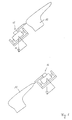
- FIG. 1 is a processing tool in two different Machining positions on a schematically represented shown with a shoe upper covered lasts 10 and generally provided with the reference number 11.
- the editing tool is located in the area the heel, while in the lower illustration the Machining tool 11 arranged in the area of the toe is.
- the dead weight acts in these two extreme positions m of the processing tool most seriously on the pressing force with which the machining tool is placed on the shoe upper works.
- the actually desired one is shown Pressure reduced by the influence of the dead weight, while in the lower illustration the pressure is about the dead weight of the machining tool 11 enlarged.
- the pneumatic circuit of the actuators (in this case pneumatic cylinder 12) of the machining tool 11, which is arranged on the arm of a machining robot (not shown), is supplemented in accordance with FIG. 2.
- the respective angular position of the machining tool 11 in space is determined at regular intervals with the aid of the robot controller using a separate robot program and transmitted as an analog signal to a pressure proportional valve 13.
- Pneumatic cylinders 12 of the machining tool 11 are acted upon by the pressure resulting from the analog signal.
- These pneumatic cylinders which are supplied with variable pressure from the proportional valve, work against two other pneumatic cylinders which are subjected to a fixed back pressure. The force difference resulting from the different pressures serves to compensate for the effective dead weight.
Landscapes
- Physics & Mathematics (AREA)
- General Physics & Mathematics (AREA)
- Engineering & Computer Science (AREA)
- Automation & Control Theory (AREA)
- Manipulator (AREA)
- Machine Tool Sensing Apparatuses (AREA)
- Turning (AREA)
- Control Of Cutting Processes (AREA)
- Numerical Control (AREA)
- Finish Polishing, Edge Sharpening, And Grinding By Specific Grinding Devices (AREA)
Abstract
Description
Die Erfindung betrifft ein Verfahren zum exakten Führen eines Bearbeitungswerkzeugs mit einem Roboter, wobei das Werkzeug mittels einer Robotersteuerung an der Kontur des zu bearbeitenden Werkstücks mit einer bestimmten Andruckkraft entlanggefahren wird, sowie eine Vorrichtung zur Durchführung des Verfahrens.The invention relates to a method for the exact management of a Machining tool with a robot, the tool by means of a robot controller on the contour of the machined Moved workpiece along with a certain pressure force is, as well as a device for performing the method.
Ein derartiges Verfahren ist beispielsweise aus der DE-A-38 15 013.1-26 bekannt. Das dort beschriebene Verfahren betrifft den industriellen Schuhherstellungsbereich.Such a method is known for example from DE-A-38 15 013.1-26 known. The method described there concerns the industrial shoe manufacturing area.
Auf einer sogenannten Rundtischanlage ist eine Vielzahl von Formstationen vorgesehen, mit Hilfe derer an auf Leisten gezogene Schäfte Gummi- oder Kunststoffsohlen angespritzt werden. Damit eine gute Verbindung zwischen Sohlenmaterial und Schaftmaterial gewährleistet ist, muß die Verbindungsfläche des Schaftes vor dem Spritzvorgang aufgerauht werden. Gegebenenfalls muß in diesem Bereich auch eine Klebeschicht aufgebracht werden. Nach dem Spritzvorgang ist es eventuell nötig, mit Hilfe eines Messers die beim Spritzvorgang entstandenen Grate abzuschneiden. Diese Vorgänge werden gemäß der zitierten Druckschrift mittels eines Roboters ausgeführt, der an seinem Arm die entsprechenden Bearbeitungswerkzeuge trägt. Die Schuhform, die Konturdaten des zu bearbeitenden Bereichs sowie die Schuhgrößen sind in der Robotersteuerung programmiert, so daß der Bearbeitungsvorgang automatisch ablaufen kann. There is a multitude of on a so-called rotary table system Forming stations provided, with the help of those drawn on strips Shafts rubber or plastic soles are molded. This ensures a good connection between the sole material and the shaft material is guaranteed, the connecting surface of the Shaft are roughened before spraying. Possibly an adhesive layer must also be applied in this area become. After the spraying process, it may be necessary to use Using a knife, the burrs created during the spraying process to cut off. These operations are cited according to the Print carried out by means of a robot, which is attached to his Arm carries the appropriate processing tools. The Shoe shape, the contour data of the area to be machined and the shoe sizes are programmed in the robot controller, so that the machining process can run automatically.
Insbesondere an Schuhansohlanlagen haben diese Bearbeitungen mit Robotern in vielen Fällen unter einem Winkel von 45° im Raum am Schuh stattzufinden. Da ein nachführendes System mit gesteuerten Andruck benötigt wird, müssen die Bearbeitungswerkzeuge zum Objekt nachgeführt werden können. Diese Beweglichkeit bedeutet aber auf der anderen Seite, daß die zu bewegenden Teile (Werkzeug, Antrieb) mit Gewichtskraft den Andruck negativ beeinflussen. So zieht die Gewichtskraft der bewegten Masse das Werkzeug im Absatzbereich vom Werkstück weg, während sie im Spitzenbereich des Schuhs den Andruck noch verstärkt.These have been processed in particular on shoe sole systems with robots in many cases at an angle of 45 ° Space to take place on the shoe. Because a tracking system with controlled pressure is required, the Editing tools can be tracked to the object. On the other hand, this mobility means that the parts to be moved (tool, drive) with weight negatively affect the pressure. So the weight pulls the moving mass the tool in the sales area of the workpiece away while they're still pressing in the toe of the shoe reinforced.
Der Erfindung liegt daher die Aufgabe zugrunde, ein Werkzeug so zu führen, daß der Andruck des Werkzeugs auf das Werkstück unabhängig von der Lage und der Winkelstellung im Raum konstant bleibt.The invention is therefore based on the object of a tool to cause the pressure of the tool on the workpiece constant regardless of the position and the angular position in the room remains.
Eine weitere Aufgabe der Erfindung besteht darin, eine geeignete Vorrichtung zur Durchführung des Verfahrens anzugeben.Another object of the invention is to find a suitable one Specify device for performing the method.
Erfindungsgemäß wird diese Aufgabe gemäß dem kennzeichnenden Teil des Anspruchs 1 dadurch gelöst, daß die jeweilige Winkelstellung des Werkzeugs im Raum in definierten Zeitabständen mit Hilfe der Robotersteuerung über ein separates Roboterprogramm ermittelt wird und als Soll-Wert an ein Regelglied übertragen wird und den dort jeweils vorliegenden Ist-Wert ersetzt und als an die Werkzeugwinkelstellung angepaßter Ausgangswert den Andruck des Werkzeugs an das Werkstück derart regelt, daß das Eigengewicht des Werkzeugs beim Andruck desselben an das Werkstück über den gesamten Bearbeitungsweg kompensiert wird.According to the invention, this object is according to the characterizing Part of claim 1 solved in that the respective angular position of the tool in the room at defined intervals Help of the robot control via a separate robot program is determined and transmitted as a target value to a control element is and the actual value present there is replaced and as output pressure adjusted to the tool angle position of the tool on the workpiece in such a way that the Dead weight of the tool when it is pressed against the workpiece is compensated for over the entire processing path.
Hiermit wird es möglich, konstante Bearbeitungsergebnisse über den gesamten Arbeitsablauf zu erhalten.This makes it possible to have constant machining results to maintain the entire workflow.
Der zweite Teil der Aufgabe wird gemäß dem kennzeichnenden Teil des Anspruchs 5 dadurch gelöst, daß den die Stellung des Bearbeitungswerkzeugs im Raum bewirkenden Aggregaten ein Regelglied vorgeschaltet ist, dessen Eingang mit einem durch ein separates Roboterprogramm in definierten Zeitabständen ermittelten, der jeweiligen Winkelstellung des Werkzeugs entsprechenden Soll-Wert beaufschlagbar ist, aufgrund dessen das Regelglied einen Ausgangswert zur Regelung der Andruckkraft des Werkzeugs am Werkstück erzeugt.The second part of the task is according to the characteristic part of claim 5 in that the position of the machining tool a control element in the units causing the room is connected upstream, the input of which is separated by a separate Robot program determined at defined time intervals, the corresponding target value for the respective angular position of the tool can be acted upon, on the basis of which the control element Initial value for controlling the pressure force of the tool on Workpiece created.
Die Ermittlung der aktuellen Winkelstellung des Werkzeugs im Raum erfolgt über die Robotersteuerung. Die Winkelstellung wird dabei aus den jeweiligen Achsdaten herausgelesen und dann als Soll-Wert an das Regelglied übertragen. Hierfür läuft das separate Roboterprogramm im Hintergrund, welches gemäß Anspruch 2 im Abstand von 0,2 Sek. die Winkelstellung ermittelt und aktualisierte Werte an das Regelglied liefert.The determination of the current angular position of the tool in the Space takes place via the robot control. The angular position will read from the respective axis data and then as Transfer the target value to the control element. For this, the runs separately Robot program in the background, which according to claim 2 the angle position is determined and updated every 0.2 seconds Delivers values to the control element.
Nach einer Grundeinstellung des Systems läuft die Gewichtskompensation automatisch im Hintergrund ab. Hierdurch können die Bearbeitungsergebnisse entscheidend verbessert werden.After a basic setting of the system, the weight compensation runs automatically in the background. This allows the Machining results are significantly improved.
In einer bevorzugten Ausführungsform der Erfindung wird als Regelglied ein Druckproportional-Ventil verwendet, wobei dieses Druckproportional-Ventil den Pneumatikzylindern vorgeschaltet ist, die die jeweilige Stellung des Bearbeitungswerkzeugs im Raum bewirken.In a preferred embodiment of the invention is used as a control element a pressure proportional valve is used, this Pressure proportional valve upstream of the pneumatic cylinders which is the respective position of the processing tool in the Create space.
Alternativ kann jedoch eine elektromechanische Lösung vorgesehen sein, wobei als Regelglied ein elektronischer Mikroprozessor vorgesehen ist und als Aggregate in diesem Fall elektrische Schrittmotoren vorgesehen werden.Alternatively, however, an electromechanical solution can be provided be, with an electronic microprocessor as the control element is provided and as aggregates in this case electrical Stepper motors are provided.
Die Erfindung wird im folgenden anhand von Zeichnungen dargestellt und näher erläutert.The invention is described below with reference to drawings shown and explained in more detail.
Es zeigen:
- Fig. 1:
- Bearbeitungswerkzeug in zwei verschiedenen Stellungen am zu bearbeitenden Schuh,
- Fig. 2:
- Schaltplan der pneumatischen Drucksteuerung für den Andruck des Bearbeitungswerkzeugs am Schuh.
- Fig. 1:
- Processing tool in two different positions on the shoe to be processed,
- Fig. 2:
- Circuit diagram of the pneumatic pressure control for pressing the processing tool on the shoe.
In der Fig. 1 ist ein Bearbeitungswerkzeug in zwei verschiedenen
Bearbeitungsstellungen an einem schematisch dargestellten
mit einem Schuhschaft bezogenen Leisten 10 dargestellt und
allgemein mit den Bezugszeichen 11 versehen. In der oberen
Darstellung befindet sich das Bearbeitungswerkzeug im Bereich
der Ferse, während in der unteren Darstellung das
Bearbeitungswerkzeug 11 im Bereich der Schuhspitze angeordnet
ist. In diesen zwei Extremstellungen wirkt sich das Eigengewicht
m des Bearbeitungswerkzeugs am gravierendsten auf die Andruckkraft
aus, mit dem das Bearbeitungswerkzeug auf den Schuhschaft
wirkt. In der obigen Darstellung wird der eigentlich gewünschte
Andruck um den Einfluß des Eigengewichts vermindert,
während sich in der unteren Darstellung der Andruck um das Eigengewicht
des Bearbeitungswerkzeugs 11 vergrößert.1 is a processing tool in two different
Machining positions on a schematically represented
shown with a shoe upper covered
Um diesen schädlichen Einfluß zu kompensieren, wird die pneumatische
Schaltung der Betätigungsorgane (in diesem Fall Pneumatikzylinder
12) des Bearbeitungswerkzeugs 11, das an dem Arm
eines Bearbeitungsroboters (nicht dargestellt) angeordnet ist,
entsprechend Fig. 2 ergänzt. Zur Kompensation des Eigengewichts
des Bearbeitungswerkzeugs 11 wird in regelmäßigen Zeitabständen
mit Hilfe der Robotersteuerung über ein separates Roboterprogramm
die jeweilige Winkelstellung des Bearbeitungswerkzeugs 11
im Raum ermittelt und als Analogsignal an ein Druck-Proportionalventil
13 übertragen. Mit dem aus dem Analogsignal
resultierenden Druck werden pneumatische Zylinder 12 des
Bearbeitungswerkzeugs 11 beaufschlagt.
Diese mit variablem Druck aus dem Proportionalventil versorgten
pneumatischen Zylinder arbeiten gegen zwei andere pneumatische
Zylinder, die mit einem festen Gegendruck beaufschlagt sind.
Die aus den unterschiedlichen Drücken resultierende
Kraftdifferenz dient zur Kompensation des wirksamen
Eigengewichts.In order to compensate for this harmful influence, the pneumatic circuit of the actuators (in this case pneumatic cylinder 12) of the
These pneumatic cylinders, which are supplied with variable pressure from the proportional valve, work against two other pneumatic cylinders which are subjected to a fixed back pressure.
The force difference resulting from the different pressures serves to compensate for the effective dead weight.
Beim Abfahren der Schaftkontur wird somit in kurzen Zeitabständen
(0,2 Sek.) abhängig von der jeweiligen Winkelstellung des
Bearbeitungswerkzeugs 11 im Raum der störende Anteil des Eigengewichts
des Bearbeitungswerkzeugs 11 kompensiert, so daß an
praktisch jedem Punkt der Kontur das Bearbeitungswerkzeug 11
mit der gewünschten Andruckkraft auf das Werkstück (Schaft)
wirkt.When the shaft contour is traversed, this is done in short time intervals
(0.2 sec.) Depending on the respective angular position of the
Claims (7)
dadurch gekennzeichnet,
daß die jeweilige Winkelstellung des Werkzeugs im Raum in definierten Zeitabständen mit Hilfe der Robotersteuerung über ein separates Roboterprogramm ermittelt wird und als Soll-Wert an ein Regelglied übertragen wird und den dort jeweils vorliegenden Ist-Wert ersetzt und als an die Werkzeugwinkelstellung angepaßter Ausgangswert den Andruck des Werkzeugs an das Werkstück derart regelt, daß das Eicengewicht des Werkzeugs beim Andruck desselben an das Werkstück über den gesamten Bearbeitungsweg kompensiert wird.Method for exact guidance of a machining tool with a robot, the tool being moved along the contour of the workpiece to be machined with a certain pressing force by means of a robot control,
characterized by
that the respective angular position of the tool in space is determined at defined time intervals with the aid of the robot controller via a separate robot program and is transmitted to a control element as the target value and replaces the actual value there, and as the output value adapted to the tool angle position, the pressure of the Tool controls the workpiece in such a way that the egg weight of the tool when it is pressed against the workpiece is compensated for over the entire machining path.
dadurch gekennzeichnet,
daß die Ermittlung der Winkelstellung des Werkzeugs im Abstand von 0,2 Sek. erfolgt. Method according to claim 1,
characterized by
that the angular position of the tool is determined every 0.2 seconds.
dadurch gekennzeichnet,
daß die Winkelstellung des Werkzeugs aus den jeweiligen Achsdaten des Roboters ermittelt wird.The method of claim 1 or 2,
characterized by
that the angular position of the tool is determined from the respective axis data of the robot.
dadurch gekennzeichnet,
daß als Regelglied ein Druckproportional-Ventil verwendet wird.Method according to one of claims 1 to 3,
characterized by
that a pressure proportional valve is used as a control element.
dadurch gekennzeichnet,
daß den die Stellung des Bearbeitungswerkzeugs (11) im Raum bewirkenden Aggregaten (12) ein Regelglied (13) vorgeschaltet ist, dessen Eingang mit einem durch ein separates Roboterprogramm in definierten Zeitabständen ermittelten, der jeweiligen Winkelstellung des Werkzeugs (11) entsprechenden Soll-Wert beaufschlagbar ist, aufgrund dessen das Regelglied (13) einen Ausgangswert (Ist-Wert) zur Regelung der Andruckkraft des Werkzeugs (11) am Werkstück (10) erzeugt.Device for carrying out the method according to one of claims 1 to 4, consisting of a robot, on the arm of which a machining tool is arranged, which, by means of units actuated by a robot controller, travels a defined curve shape corresponding to the contour of the workpiece to be machined with a specific pressing force,
characterized by
that the units (12) causing the position of the machining tool (11) in space are preceded by a control element (13), the input of which can be acted upon by a desired value corresponding to the respective angular position of the tool (11), determined by a separate robot program at defined time intervals , on the basis of which the control element (13) generates an initial value (actual value) for regulating the pressing force of the tool (11) on the workpiece (10).
dadurch gekennzeichnet,
daß das Regelglied (13) ein Druckproportional-Ventil ist und die Aggregate (12) Pneumatikzylinder sind.Device according to claim 5,
characterized by
that the control element (13) is a pressure proportional valve and the units (12) are pneumatic cylinders.
dadurch gekennzeichnet,
daß das Regelglied ein elektronischer Mikroprozessor ist und die Aggregate elektrische Schrittmotoren sind.Device according to claim 5,
characterized by
that the control element is an electronic microprocessor and the units are electric stepper motors.
Applications Claiming Priority (2)
| Application Number | Priority Date | Filing Date | Title |
|---|---|---|---|
| DE10010689 | 2000-03-04 | ||
| DE10010689A DE10010689C1 (en) | 2000-03-04 | 2000-03-04 | Machining tool guiding method for robot controlled machining detects actual angular position of machining tool at defined intervals for feedback regulation of tool pressure |
Publications (3)
| Publication Number | Publication Date |
|---|---|
| EP1130486A2 true EP1130486A2 (en) | 2001-09-05 |
| EP1130486A3 EP1130486A3 (en) | 2003-01-08 |
| EP1130486B1 EP1130486B1 (en) | 2006-06-21 |
Family
ID=7633564
Family Applications (1)
| Application Number | Title | Priority Date | Filing Date |
|---|---|---|---|
| EP00126036A Expired - Lifetime EP1130486B1 (en) | 2000-03-04 | 2000-11-29 | Method and device for accurate guiding of a machining tool with a robot |
Country Status (8)
| Country | Link |
|---|---|
| EP (1) | EP1130486B1 (en) |
| JP (1) | JP2001269886A (en) |
| CN (1) | CN1155457C (en) |
| AT (1) | ATE331242T1 (en) |
| DE (2) | DE10010689C1 (en) |
| ES (1) | ES2265858T3 (en) |
| PT (1) | PT1130486E (en) |
| TW (1) | TW473419B (en) |
Families Citing this family (5)
| Publication number | Priority date | Publication date | Assignee | Title |
|---|---|---|---|---|
| JP4938353B2 (en) * | 2006-05-18 | 2012-05-23 | リンテック株式会社 | Sheet cutting device and cutting method |
| TWI531328B (en) * | 2011-07-28 | 2016-05-01 | 克洛克納得斯馬製鞋機械有限公司 | Method to process technical objects, in particular, parts for shoes |
| DE102012106616A1 (en) * | 2012-07-20 | 2014-01-23 | Fritz Studer Ag | Machine tool with a spindle head and method for positioning a spindle head of a machine tool |
| DE102014015183A1 (en) | 2014-10-15 | 2015-04-23 | Daimler Ag | Apparatus and method for machining a workpiece |
| DE102019202515A1 (en) * | 2019-02-25 | 2020-08-27 | Kuka Deutschland Gmbh | Method for the automatic fitting of a shoe upper onto a last |
Citations (3)
| Publication number | Priority date | Publication date | Assignee | Title |
|---|---|---|---|---|
| DE3815013A1 (en) * | 1988-05-04 | 1989-11-16 | Kloeckner Ferromatik Desma | METHOD AND DEVICE FOR MOLDING UP MULTILAYER SOLE ON SHOE SHOES, IF ANY |
| US5509848A (en) * | 1992-11-10 | 1996-04-23 | Mazda Motor Corporation | Method of and apparatus for polishing painted surfaces |
| WO1998042482A1 (en) * | 1997-03-04 | 1998-10-01 | Abb Ab | A method for determining load parameters for a manipulator |
-
2000
- 2000-03-04 DE DE10010689A patent/DE10010689C1/en not_active Expired - Fee Related
- 2000-11-29 AT AT00126036T patent/ATE331242T1/en not_active IP Right Cessation
- 2000-11-29 PT PT00126036T patent/PT1130486E/en unknown
- 2000-11-29 ES ES00126036T patent/ES2265858T3/en not_active Expired - Lifetime
- 2000-11-29 EP EP00126036A patent/EP1130486B1/en not_active Expired - Lifetime
- 2000-11-29 DE DE50013048T patent/DE50013048D1/en not_active Expired - Lifetime
- 2000-12-05 TW TW089125852A patent/TW473419B/en not_active IP Right Cessation
-
2001
- 2001-02-13 CN CNB011038071A patent/CN1155457C/en not_active Expired - Lifetime
- 2001-03-01 JP JP2001056600A patent/JP2001269886A/en active Pending
Patent Citations (3)
| Publication number | Priority date | Publication date | Assignee | Title |
|---|---|---|---|---|
| DE3815013A1 (en) * | 1988-05-04 | 1989-11-16 | Kloeckner Ferromatik Desma | METHOD AND DEVICE FOR MOLDING UP MULTILAYER SOLE ON SHOE SHOES, IF ANY |
| US5509848A (en) * | 1992-11-10 | 1996-04-23 | Mazda Motor Corporation | Method of and apparatus for polishing painted surfaces |
| WO1998042482A1 (en) * | 1997-03-04 | 1998-10-01 | Abb Ab | A method for determining load parameters for a manipulator |
Also Published As
| Publication number | Publication date |
|---|---|
| PT1130486E (en) | 2006-10-31 |
| DE10010689C1 (en) | 2001-04-12 |
| DE50013048D1 (en) | 2006-08-03 |
| EP1130486B1 (en) | 2006-06-21 |
| EP1130486A3 (en) | 2003-01-08 |
| ES2265858T3 (en) | 2007-03-01 |
| ATE331242T1 (en) | 2006-07-15 |
| CN1311082A (en) | 2001-09-05 |
| CN1155457C (en) | 2004-06-30 |
| TW473419B (en) | 2002-01-21 |
| JP2001269886A (en) | 2001-10-02 |
Similar Documents
| Publication | Publication Date | Title |
|---|---|---|
| DE3815013C2 (en) | ||
| EP2223191B1 (en) | Industrial robot and method for programming an industrial robot | |
| DE3249988C2 (en) | Tape application head | |
| DE69713921T2 (en) | Welding system and method for setting parameters of a welding device | |
| DE602004010262T2 (en) | METHOD FOR MOVING A CAMERA DEVICE TO A TARGET POSITION THROUGH A CONTROL TYPE AND CONTROL SYSTEM THEREFOR | |
| DE19933294B4 (en) | Method and device for holding one or more layers of cloth-like working material on a support surface | |
| EP0485542B1 (en) | Process and device for setting up a three-cutter machine | |
| EP0192605A1 (en) | Sealing device in a machine with welding and/or sealing jaws for making bags from a tubular web | |
| DE102011011542A1 (en) | Method for automated programming and optimization of robotic workflows | |
| EP2600992A1 (en) | Bending press with a workpiece positioning device and an operating method | |
| DE102017103867A1 (en) | Method for operating a machine tool, in particular a plate processing system for processing plate-shaped workpieces, and a machine tool | |
| DE102014226933B3 (en) | Device and method for recording positions | |
| DE3439096C2 (en) | ||
| DE4439284C3 (en) | Device and method for the continuous ultrasonic processing of a material web | |
| EP3482859A1 (en) | Machine tool, in particular sawing machine and system for the optimal operation of a machine tool | |
| EP2845661A1 (en) | Method for bending work pieces | |
| DE10010689C1 (en) | Machining tool guiding method for robot controlled machining detects actual angular position of machining tool at defined intervals for feedback regulation of tool pressure | |
| DE102018008698A1 (en) | Device and method for producing a rotor blade for a wind energy installation and wind energy installation | |
| EP1115499B1 (en) | Powder coating device | |
| EP3890932B1 (en) | Supply system, method to equip a supply device with a coating material and use | |
| DE2406493C2 (en) | Programmable servo system for guiding a tool, especially a spray gun | |
| EP3822014A1 (en) | Method for scanning the surface of metallic workpieces | |
| DE2640883A1 (en) | AUTOMATIC DEVICE FOR POSITIONING THE EDGE OF A RUNNING BELT | |
| DE3249987C2 (en) | Appts. for mfg. composite by laying fibre resin tape on mould | |
| EP3235399A1 (en) | Method and device for selectively applying a cover varnish |
Legal Events
| Date | Code | Title | Description |
|---|---|---|---|
| PUAI | Public reference made under article 153(3) epc to a published international application that has entered the european phase |
Free format text: ORIGINAL CODE: 0009012 |
|
| AK | Designated contracting states |
Kind code of ref document: A2 Designated state(s): AT BE CH CY DE DK ES FI FR GB GR IE IT LI LU MC NL PT SE TR |
|
| AX | Request for extension of the european patent |
Free format text: AL;LT;LV;MK;RO;SI |
|
| PUAL | Search report despatched |
Free format text: ORIGINAL CODE: 0009013 |
|
| AK | Designated contracting states |
Kind code of ref document: A3 Designated state(s): AT BE CH CY DE DK ES FI FR GB GR IE IT LI LU MC NL PT SE TR |
|
| AX | Request for extension of the european patent |
Free format text: AL;LT;LV;MK;RO;SI |
|
| 17P | Request for examination filed |
Effective date: 20030326 |
|
| AKX | Designation fees paid |
Designated state(s): AT BE CH CY DE DK ES FI FR GB GR IE IT LI LU MC NL PT SE TR |
|
| 17Q | First examination report despatched |
Effective date: 20050214 |
|
| GRAP | Despatch of communication of intention to grant a patent |
Free format text: ORIGINAL CODE: EPIDOSNIGR1 |
|
| GRAS | Grant fee paid |
Free format text: ORIGINAL CODE: EPIDOSNIGR3 |
|
| GRAA | (expected) grant |
Free format text: ORIGINAL CODE: 0009210 |
|
| AK | Designated contracting states |
Kind code of ref document: B1 Designated state(s): AT BE CH CY DE DK ES FI FR GB GR IE IT LI LU MC NL PT SE TR |
|
| PG25 | Lapsed in a contracting state [announced via postgrant information from national office to epo] |
Ref country code: IT Free format text: LAPSE BECAUSE OF FAILURE TO SUBMIT A TRANSLATION OF THE DESCRIPTION OR TO PAY THE FEE WITHIN THE PRESCRIBED TIME-LIMIT;WARNING: LAPSES OF ITALIAN PATENTS WITH EFFECTIVE DATE BEFORE 2007 MAY HAVE OCCURRED AT ANY TIME BEFORE 2007. THE CORRECT EFFECTIVE DATE MAY BE DIFFERENT FROM THE ONE RECORDED. Effective date: 20060621 Ref country code: GB Free format text: LAPSE BECAUSE OF FAILURE TO SUBMIT A TRANSLATION OF THE DESCRIPTION OR TO PAY THE FEE WITHIN THE PRESCRIBED TIME-LIMIT Effective date: 20060621 Ref country code: IE Free format text: LAPSE BECAUSE OF FAILURE TO SUBMIT A TRANSLATION OF THE DESCRIPTION OR TO PAY THE FEE WITHIN THE PRESCRIBED TIME-LIMIT Effective date: 20060621 |
|
| REG | Reference to a national code |
Ref country code: GB Ref legal event code: FG4D Free format text: NOT ENGLISH |
|
| REG | Reference to a national code |
Ref country code: CH Ref legal event code: EP |
|
| REG | Reference to a national code |
Ref country code: IE Ref legal event code: FG4D Free format text: LANGUAGE OF EP DOCUMENT: GERMAN |
|
| REF | Corresponds to: |
Ref document number: 50013048 Country of ref document: DE Date of ref document: 20060803 Kind code of ref document: P |
|
| PG25 | Lapsed in a contracting state [announced via postgrant information from national office to epo] |
Ref country code: DK Free format text: LAPSE BECAUSE OF FAILURE TO SUBMIT A TRANSLATION OF THE DESCRIPTION OR TO PAY THE FEE WITHIN THE PRESCRIBED TIME-LIMIT Effective date: 20060921 Ref country code: SE Free format text: LAPSE BECAUSE OF FAILURE TO SUBMIT A TRANSLATION OF THE DESCRIPTION OR TO PAY THE FEE WITHIN THE PRESCRIBED TIME-LIMIT Effective date: 20060921 |
|
| REG | Reference to a national code |
Ref country code: PT Ref legal event code: SC4A Effective date: 20060913 |
|
| PG25 | Lapsed in a contracting state [announced via postgrant information from national office to epo] |
Ref country code: MC Free format text: LAPSE BECAUSE OF NON-PAYMENT OF DUE FEES Effective date: 20061130 Ref country code: LI Free format text: LAPSE BECAUSE OF NON-PAYMENT OF DUE FEES Effective date: 20061130 Ref country code: BE Free format text: LAPSE BECAUSE OF NON-PAYMENT OF DUE FEES Effective date: 20061130 Ref country code: CH Free format text: LAPSE BECAUSE OF NON-PAYMENT OF DUE FEES Effective date: 20061130 |
|
| REG | Reference to a national code |
Ref country code: IE Ref legal event code: FD4D |
|
| GBV | Gb: ep patent (uk) treated as always having been void in accordance with gb section 77(7)/1977 [no translation filed] |
Effective date: 20060621 |
|
| ET | Fr: translation filed | ||
| REG | Reference to a national code |
Ref country code: ES Ref legal event code: FG2A Ref document number: 2265858 Country of ref document: ES Kind code of ref document: T3 |
|
| PLBE | No opposition filed within time limit |
Free format text: ORIGINAL CODE: 0009261 |
|
| STAA | Information on the status of an ep patent application or granted ep patent |
Free format text: STATUS: NO OPPOSITION FILED WITHIN TIME LIMIT |
|
| 26N | No opposition filed |
Effective date: 20070322 |
|
| REG | Reference to a national code |
Ref country code: CH Ref legal event code: PL |
|
| BERE | Be: lapsed |
Owner name: KLOCKNER DESMA SCHUHMASCHINEN G.M.B.H. Effective date: 20061130 |
|
| PG25 | Lapsed in a contracting state [announced via postgrant information from national office to epo] |
Ref country code: AT Free format text: LAPSE BECAUSE OF NON-PAYMENT OF DUE FEES Effective date: 20061129 |
|
| PG25 | Lapsed in a contracting state [announced via postgrant information from national office to epo] |
Ref country code: GR Free format text: LAPSE BECAUSE OF FAILURE TO SUBMIT A TRANSLATION OF THE DESCRIPTION OR TO PAY THE FEE WITHIN THE PRESCRIBED TIME-LIMIT Effective date: 20060922 |
|
| PG25 | Lapsed in a contracting state [announced via postgrant information from national office to epo] |
Ref country code: LU Free format text: LAPSE BECAUSE OF NON-PAYMENT OF DUE FEES Effective date: 20061129 Ref country code: TR Free format text: LAPSE BECAUSE OF FAILURE TO SUBMIT A TRANSLATION OF THE DESCRIPTION OR TO PAY THE FEE WITHIN THE PRESCRIBED TIME-LIMIT Effective date: 20060621 |
|
| PG25 | Lapsed in a contracting state [announced via postgrant information from national office to epo] |
Ref country code: CY Free format text: LAPSE BECAUSE OF FAILURE TO SUBMIT A TRANSLATION OF THE DESCRIPTION OR TO PAY THE FEE WITHIN THE PRESCRIBED TIME-LIMIT Effective date: 20060621 |
|
| REG | Reference to a national code |
Ref country code: FR Ref legal event code: PLFP Year of fee payment: 16 |
|
| PGFP | Annual fee paid to national office [announced via postgrant information from national office to epo] |
Ref country code: FI Payment date: 20151124 Year of fee payment: 16 |
|
| PGFP | Annual fee paid to national office [announced via postgrant information from national office to epo] |
Ref country code: NL Payment date: 20151127 Year of fee payment: 16 Ref country code: FR Payment date: 20151127 Year of fee payment: 16 |
|
| REG | Reference to a national code |
Ref country code: NL Ref legal event code: MM Effective date: 20161201 |
|
| PG25 | Lapsed in a contracting state [announced via postgrant information from national office to epo] |
Ref country code: FI Free format text: LAPSE BECAUSE OF NON-PAYMENT OF DUE FEES Effective date: 20161129 |
|
| REG | Reference to a national code |
Ref country code: FR Ref legal event code: ST Effective date: 20170731 |
|
| PG25 | Lapsed in a contracting state [announced via postgrant information from national office to epo] |
Ref country code: NL Free format text: LAPSE BECAUSE OF NON-PAYMENT OF DUE FEES Effective date: 20161201 |
|
| PG25 | Lapsed in a contracting state [announced via postgrant information from national office to epo] |
Ref country code: FR Free format text: LAPSE BECAUSE OF NON-PAYMENT OF DUE FEES Effective date: 20161130 |
|
| PGFP | Annual fee paid to national office [announced via postgrant information from national office to epo] |
Ref country code: PT Payment date: 20181123 Year of fee payment: 19 Ref country code: DE Payment date: 20181120 Year of fee payment: 19 |
|
| PGFP | Annual fee paid to national office [announced via postgrant information from national office to epo] |
Ref country code: ES Payment date: 20181218 Year of fee payment: 19 Ref country code: IT Payment date: 20181126 Year of fee payment: 19 |
|
| REG | Reference to a national code |
Ref country code: DE Ref legal event code: R119 Ref document number: 50013048 Country of ref document: DE |
|
| PG25 | Lapsed in a contracting state [announced via postgrant information from national office to epo] |
Ref country code: PT Free format text: LAPSE BECAUSE OF NON-PAYMENT OF DUE FEES Effective date: 20200702 Ref country code: DE Free format text: LAPSE BECAUSE OF NON-PAYMENT OF DUE FEES Effective date: 20200603 Ref country code: IT Free format text: LAPSE BECAUSE OF NON-PAYMENT OF DUE FEES Effective date: 20191129 |
|
| REG | Reference to a national code |
Ref country code: ES Ref legal event code: FD2A Effective date: 20210528 |
|
| PG25 | Lapsed in a contracting state [announced via postgrant information from national office to epo] |
Ref country code: ES Free format text: LAPSE BECAUSE OF NON-PAYMENT OF DUE FEES Effective date: 20191130 |