EP1130321A1 - Combustor liner cooling thimbles and related method - Google Patents
Combustor liner cooling thimbles and related method Download PDFInfo
- Publication number
- EP1130321A1 EP1130321A1 EP01301691A EP01301691A EP1130321A1 EP 1130321 A1 EP1130321 A1 EP 1130321A1 EP 01301691 A EP01301691 A EP 01301691A EP 01301691 A EP01301691 A EP 01301691A EP 1130321 A1 EP1130321 A1 EP 1130321A1
- Authority
- EP
- European Patent Office
- Prior art keywords
- cooling
- flow sleeve
- liner
- combustor
- rows
- Prior art date
- Legal status (The legal status is an assumption and is not a legal conclusion. Google has not performed a legal analysis and makes no representation as to the accuracy of the status listed.)
- Granted
Links
- 238000001816 cooling Methods 0.000 title claims abstract description 83
- 238000000034 method Methods 0.000 title claims abstract description 9
- 230000007704 transition Effects 0.000 claims abstract description 29
- 239000007789 gas Substances 0.000 claims abstract description 10
- 239000000567 combustion gas Substances 0.000 claims abstract description 4
- 238000002485 combustion reaction Methods 0.000 claims description 9
- 239000000446 fuel Substances 0.000 description 3
- 238000005452 bending Methods 0.000 description 2
- 230000000593 degrading effect Effects 0.000 description 2
- 238000010586 diagram Methods 0.000 description 2
- 238000011144 upstream manufacturing Methods 0.000 description 2
- 230000000712 assembly Effects 0.000 description 1
- 238000000429 assembly Methods 0.000 description 1
- 230000015572 biosynthetic process Effects 0.000 description 1
- 238000006243 chemical reaction Methods 0.000 description 1
- 238000005336 cracking Methods 0.000 description 1
- 230000007423 decrease Effects 0.000 description 1
- 230000002708 enhancing effect Effects 0.000 description 1
- 238000002347 injection Methods 0.000 description 1
- 239000007924 injection Substances 0.000 description 1
- 230000007246 mechanism Effects 0.000 description 1
- 230000010355 oscillation Effects 0.000 description 1
- 230000003068 static effect Effects 0.000 description 1
Images



Classifications
-
- F—MECHANICAL ENGINEERING; LIGHTING; HEATING; WEAPONS; BLASTING
- F02—COMBUSTION ENGINES; HOT-GAS OR COMBUSTION-PRODUCT ENGINE PLANTS
- F02C—GAS-TURBINE PLANTS; AIR INTAKES FOR JET-PROPULSION PLANTS; CONTROLLING FUEL SUPPLY IN AIR-BREATHING JET-PROPULSION PLANTS
- F02C7/00—Features, components parts, details or accessories, not provided for in, or of interest apart form groups F02C1/00 - F02C6/00; Air intakes for jet-propulsion plants
- F02C7/12—Cooling of plants
- F02C7/16—Cooling of plants characterised by cooling medium
- F02C7/18—Cooling of plants characterised by cooling medium the medium being gaseous, e.g. air
-
- F—MECHANICAL ENGINEERING; LIGHTING; HEATING; WEAPONS; BLASTING
- F23—COMBUSTION APPARATUS; COMBUSTION PROCESSES
- F23R—GENERATING COMBUSTION PRODUCTS OF HIGH PRESSURE OR HIGH VELOCITY, e.g. GAS-TURBINE COMBUSTION CHAMBERS
- F23R3/00—Continuous combustion chambers using liquid or gaseous fuel
- F23R3/002—Wall structures
-
- F—MECHANICAL ENGINEERING; LIGHTING; HEATING; WEAPONS; BLASTING
- F23—COMBUSTION APPARATUS; COMBUSTION PROCESSES
- F23R—GENERATING COMBUSTION PRODUCTS OF HIGH PRESSURE OR HIGH VELOCITY, e.g. GAS-TURBINE COMBUSTION CHAMBERS
- F23R3/00—Continuous combustion chambers using liquid or gaseous fuel
- F23R3/02—Continuous combustion chambers using liquid or gaseous fuel characterised by the air-flow or gas-flow configuration
- F23R3/04—Air inlet arrangements
- F23R3/06—Arrangement of apertures along the flame tube
-
- F—MECHANICAL ENGINEERING; LIGHTING; HEATING; WEAPONS; BLASTING
- F23—COMBUSTION APPARATUS; COMBUSTION PROCESSES
- F23R—GENERATING COMBUSTION PRODUCTS OF HIGH PRESSURE OR HIGH VELOCITY, e.g. GAS-TURBINE COMBUSTION CHAMBERS
- F23R2900/00—Special features of, or arrangements for continuous combustion chambers; Combustion processes therefor
- F23R2900/03044—Impingement cooled combustion chamber walls or subassemblies
Definitions
- Each combustor assembly includes a cylindrical liner, a fuel injection system, and a transition piece that guides the flow of the hot gas from the combustor to the inlet of the turbine.
- a portion of the compressor discharge air is used to cool the combustion liner and is then introduced into the combustor reaction zone to be mixed with the fuel and burned.
- a hollow sleeve surrounds the transition piece, and the sleeve wall is perforated so that compressor discharge air will flow through the cooling apertures in the sleeve wall and impinge upon (and thus cool) the transition piece.
- This cooling air then flows along an annulus between the sleeve surrounding the transition piece, and the transition piece itself. This so-called "cross flow” eventually flows into another annulus between the combustion liner and a surrounding flow sleeve.
- the flow sleeve is also formed with several rows of cooling holes around its circumference, the first row located adjacent a mounting flange where the flow sleeve joins to the outer sleeve of the transition piece. The cross flow is perpendicular to impingement cooling air flowing through the holes in the flow sleeve toward the combustor liner surface.
- this crossflow has a direct influence on the cooling effectiveness in the zone near where the first row of jets in the flow sleeve would have been expected to impingement cool the combustor liner.
- the crossflow impacts the first row of flow sleeve jets, bending them over and degrading their ability to impinge upon the liner.
- the flow sleeve impingement jets there are three rows of 24 jets spaced evenly around the circumference of the flow sleeve. This jet pattern in the presence of the strong crossflow from the transition piece impingement sleeve produces very low heat transfer rates on the liner surface near the first row of jets. This low heat transfer rate can lead to high liner surface temperatures and ultimately loss of strength.
- a typical gas turbine includes a transition piece 10 by which the hot combustion gases from an upstream combustor as represented by the combustion liner 12 are passed to the first stage of a turbine represented at 14.
- Flow from the gas turbine compressor exits an axial diffuser 16 and enters into a compressor discharge case 18.
- About 50% of the compressor discharge air passes through apertures 20 formed along and about a transition piece impingement sleeve 22 for flow in an annular region or annulus 24 between the transition piece 10 and the radially outer transition piece impingement sleeve 22.
- the remaining approximately 50% of the compressor discharge flow passes into flow sleeve holes 34 and mixes with the air from the transition piece from annulus 30 and eventually mixes with the gas turbine fuel in the combustor.
- the impingement sleeve 22 of the transition piece 10 is received in a telescoping relationship in a mounting flange 26 on the aft end of the combustor flow sleeve 28, and the transition piece 10 also receives the combustor liner 12 in a telescoping relationship.
- the combustor flow sleeve 28 surrounds the combustor liner 12 creating a flow annulus 30 therebetween.
Landscapes
- Engineering & Computer Science (AREA)
- Chemical & Material Sciences (AREA)
- Combustion & Propulsion (AREA)
- Mechanical Engineering (AREA)
- General Engineering & Computer Science (AREA)
- Turbine Rotor Nozzle Sealing (AREA)
- Vertical, Hearth, Or Arc Furnaces (AREA)
Abstract
Description
- This invention relates to combustors in turbo machinery and specifically, to the cooling of combustor liners in gas turbine combustors.
- Conventional gas turbine combustion systems employ multiple combustor assemblies to achieve reliable and efficient turbine operation. Each combustor assembly includes a cylindrical liner, a fuel injection system, and a transition piece that guides the flow of the hot gas from the combustor to the inlet of the turbine. Generally, a portion of the compressor discharge air is used to cool the combustion liner and is then introduced into the combustor reaction zone to be mixed with the fuel and burned.
- In systems incorporating impingement cooled transition pieces, a hollow sleeve surrounds the transition piece, and the sleeve wall is perforated so that compressor discharge air will flow through the cooling apertures in the sleeve wall and impinge upon (and thus cool) the transition piece. This cooling air then flows along an annulus between the sleeve surrounding the transition piece, and the transition piece itself. This so-called "cross flow" eventually flows into another annulus between the combustion liner and a surrounding flow sleeve. The flow sleeve is also formed with several rows of cooling holes around its circumference, the first row located adjacent a mounting flange where the flow sleeve joins to the outer sleeve of the transition piece. The cross flow is perpendicular to impingement cooling air flowing through the holes in the flow sleeve toward the combustor liner surface.
- The presence of this crossflow has a direct influence on the cooling effectiveness in the zone near where the first row of jets in the flow sleeve would have been expected to impingement cool the combustor liner. Specifically, the crossflow impacts the first row of flow sleeve jets, bending them over and degrading their ability to impinge upon the liner. In one prior design of the flow sleeve impingement jets there are three rows of 24 jets spaced evenly around the circumference of the flow sleeve. This jet pattern in the presence of the strong crossflow from the transition piece impingement sleeve produces very low heat transfer rates on the liner surface near the first row of jets. This low heat transfer rate can lead to high liner surface temperatures and ultimately loss of strength. Several potential failure modes due to the high temperature of the liner include, but are not limited to, cracking of the aft sleeve weld line, bulging and triangulation. These mechanisms shorten the life of the liner, requiring replacement of the part prematurely.
- This invention enhances the cooling of the liner in Dry Low NOx type gas turbine combustors where jet impingement is used to cool the aft portion of the combustor liner. Even though there is a strong crossflow resulting from the transition piece cooling flow, the negative impact of the crossflow is minimized by the use of collars or cooling conduits, also referred to as a thimbles, that are inserted into the cooling holes in the combustor liner flow sleeve, through which the cooling jets pass. These thimbles provide a physical blockage to the cross flow which forces the crossflow into the desired flow path while simultaneously ensuring that the cooling jets effectively impinge on the combustor liner surface to be cooled.
- The thimbles or collars are preferably mounted in each hole of at least the first row of holes at the aft end of the flow sleeve, adjacent a mounting flange where the combustor liner and transition piece are joined. This arrangement decreases the gap between the jet orifice and impingement surface; blocks the cross flow that deflects the jets and forces it into the desired flowpath for the subsequent jet rows; allows the diameter of the jet to be smaller and thereby reduce cooling air; and provides consistent and accurate control over the location of jet impingement. It also stabilizes unwanted axial oscillation of the first row of jets, and prevents the formation of a thick boundary layer (and resulting reduced heat transfer) upstream of the first row of jets.
- Accordingly, in its broader aspects, this invention relates to a combustor for a turbine that includes: a combustor liner; a first flow sleeve surrounding the liner, the flow sleeve having a plurality of rows of cooling holes formed about a circumference of the flow sleeve; a transition piece connected to the combustor liner and the flow sleeve and adapted to carry hot combustion gases to a stage of the turbine; the transition piece surrounded by a second flow sleeve; wherein a first of the plurality of rows of cooing holes in the first flow sleeve is located adjacent the transition piece; and further wherein one or more cooling conduits are mounted in the cooling holes of at least the first of the plurality of rows of cooling holes.
- In another aspect, the invention relates to combustion liner flow sleeve adapted for mounting in surrounding relationship to a combustion liner, the flow sleeve comprising a tubular body formed with plural rows of cooling holes, one of the plural rows located adjacent one end of the flow sleeve; and a cooling conduit mounted in each hole of at least the first row of holes, the cooling conduits projecting radially into the flow sleeve.
- In still another aspect, the invention relates to a method of cooling a combustor liner of a gas turbine combustor, the combustor liner having a substantially circular cross-section, and a flow sleeve surrounding the liner in substantially concentric relationship therewith creating an annulus therebetween; the method comprising a) providing a plurality of axially spaced rows of cooling holes in the flow sleeve, each row extending circumferentially of the flow sleeve, one of the rows adjacent a forward or downstream end of the flow sleeve; b) locating a plurality of cooling conduits in the cooling holes of at least the first of the rows, the cooling conduits extending radially towards, but not engaging, the liner; and c) supplying cooling air to the annulus such that the cooling conduits direct the cooling air against the liner.
- An embodiment of the invention will now be described, by way of example, with reference to the accompanying drawings, in which:-
- FIGURE 1 is a simplified side cross section of a combustor transition piece aft of the combustor liner;
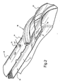
- FIGURE 2 is a partial but more detailed perspective of a combustor liner and flow sleeve joined to the transition piece;
- FIGURE 3 is a flow diagram illustrating impingement cooling of the combustor liner in a prior arrangement;
- FIGURE 4 is a side elevation of a cooling thimble in accordance with the invention;
- FIGURE 5 is a side section of the thimble shown in Figure 4; and
- FIGURE 6 is a flow diagram illustrating impingement cooling of the combustor liner in accordance with this invention.
-
- With reference to Figures 1 and 2, a typical gas turbine includes a
transition piece 10 by which the hot combustion gases from an upstream combustor as represented by thecombustion liner 12 are passed to the first stage of a turbine represented at 14. Flow from the gas turbine compressor exits anaxial diffuser 16 and enters into acompressor discharge case 18. About 50% of the compressor discharge air passes throughapertures 20 formed along and about a transitionpiece impingement sleeve 22 for flow in an annular region orannulus 24 between thetransition piece 10 and the radially outer transitionpiece impingement sleeve 22. The remaining approximately 50% of the compressor discharge flow passes intoflow sleeve holes 34 and mixes with the air from the transition piece fromannulus 30 and eventually mixes with the gas turbine fuel in the combustor. - As best seen in Figure 2, the
impingement sleeve 22 of thetransition piece 10 is received in a telescoping relationship in amounting flange 26 on the aft end of thecombustor flow sleeve 28, and thetransition piece 10 also receives thecombustor liner 12 in a telescoping relationship. Thecombustor flow sleeve 28 surrounds thecombustor liner 12 creating aflow annulus 30 therebetween. It can be seen from theflow arrow 32 in Figure 2, that crossflow cooling air traveling in theannulus 24 continues to flow into theannulus 30 in a direction perpendicular to impingement cooling air flowing through the cooling holes 34 (see flow arrow 35) formed about the circumference of the flow sleeve 28 (while three rows are shown in Fig. 2, the flow sleeve may have any number of rows of such holes). - The impingement cooling flow in the first row of
holes 34 in the flow sleeve (the row of holes closest to the mounting flange 26) is particularly subject to disruption by the crossflow from theannulus 24. The negative impact can be seen in Figure 3. The test impingement sleeve/combustor liner configuration shown in Figure 3 is slightly different than the arrangement in Figure 2, but similar reference numerals are used for ease of understanding. The cross flow impacts on the first row of cooling jets exiting theholes 34, bending them over and degrading their ability to impinge upon theliner 12. Depending on the relative strengths of the cross flow and jets, the jet flow may not even reach the surface of thecombustor liner 12. Because the impingement jets are high velocity, there is a characteristic zone of low static pressure behind the jets and near the flow sleeve entrance hole. The cross flow accelerates toward the low pressure zone, leading to a velocity gradient across the flow sleeve/liner annulus 30. The resulting low velocity and thickened boundary layer near the liner surface has very poor heat transfer effectiveness. - To neutralize the negative impact of the crossflow on the cooling jets,
cooling thimbles 36 as shown in Figure 4 are employed. These thimbles may comprisetubes 38 of circular cross section, with a flat ring orflange 40 welded to its top. The dimensions of thethimbles 36 are set by the liner/flow sleeve gap, the tolerance of this dimension, the jet and cross flow momentum, the geometric constraints of the thimble, and the specific cooling requirements. Asingle thimble 36 is inserted into each of the first rowflow sleeve holes 34 and welded at the ring or flange 40 to the outside of theflow sleeve 28. There are 20 thimbles mounted in a like number ofholes 34 around the circumference of theflow sleeve 28 in at least the first rowadjacent mounting flange 26, but they could be added to the second and/or third row as well. The critical location to be cooled in one exemplary embodiment, has been determined to be about 30 inches from the opposite end of the flow sleeve (not shown). - The cross section of the
tube 38 is shown to be circular but other cross-sectional shapes could be used, e.g., square, triangular, airfoil-shaped, semi-circular and the like. An open channel-shape could also be used. - Figure 6 shows a cross section revealing the flow field in the liner/flow sleeve annulus with the
thimbles 36 in place. This figure may be contrasted with Figure 3 to identify the benefits of enhancing first row jets by use of flow sleeve thimbles. It is particularly evident that impingement cooling of theliner 12 is enhanced at the first row ofholes 36, and that the crossflow has been blocked at least to the extent of allowing cooling jets from theimpingement cooling holes 34 to reach the surface of theliner 12. In fact, it has been established that the thimbles add 150 BTU/HR*ft2*F to the liner heat transfer coefficient at the first row jet centerline, 29.2 inches from the opposite end of the flow sleeve. - The device and process in accordance with this invention can be used in any impingement cooling application where there is a crossflow present at the first row of jets.
Claims (9)
- A combustor for a turbine comprising:a combustor liner (12);a first flow sleeve (28) surrounding said liners said flow sleeve having a plurality of rows of cooling holes (34) formed about a circumference of said flow sleeve;a transition piece (10) connected to said combustor liner (12) and said flow sleeve (28) and adapted to carry hot combustion gases to a stage (14) of the turbine; said transition piece surrounded by a second flow sleeve (22); wherein a first of said plurality of rows of cooling holes (34) in said first flow sleeve is located adjacent said transition piece; and further wherein one or more cooling conduits (36) are mounted in the cooling holes (34) of at least said first of said plurality of rows of cooling holes.
- The combustor of claim 1 wherein said cooling conduits each include a tube (38) with a radial flange (40) at one end thereof.
- The combustor of claim 2 wherein each said cooling conduit is welded to said flow sleeve, with an opposite end of said tube spaced from said liner by a predetermined space.
- The combustor of claim 2 wherein one of said plurality of cooling conduits (36) are circular in cross-section.
- A combustion liner flow sleeve adapted for mounting in surrounding relationship to a combustion liner, said flow sleeve comprising a tubular body (28) formed with plural rows of cooling holes (34), one of said plural rows located adjacent one end of said flow sleeve; and a cooling circuit (36) mounted in each hole of at least said first row of holes, said cooling conduit projecting radially into said flow sleeve.
- The combustion liner flow sleeve of claim 5 wherein said cooling conduits each include a tube (38) with a radial flange (40) at one end thereof.
- A method of cooling a combustor liner (12) of a gas turbine combustor, said combustor liner having a substantially circular cross-section, and a flow sleeve (28) surrounding said liner in substantially concentric relationship therewith creating an annulus (30) therebetween; the method comprising:a) providing a plurality of axially spaced rows of cooling holes (34) in said flow sleeve, each row extending circumferentially of said flow sleeve, a first of said rows adjacent a forward or downstream end of said flow sleeve;b) locating a plurality of cooling conduits (36) in the cooling holes (34) of at least said first of said rows, said cooling conduits extending radially towards, but not engaging, said liner; andc) supplying cooling air to said cooling holes (34) such that said cooling conduits (36) direct said cooling air against said liner (12).
- The method of claim 7 wherein said cooling conduits each include a tube with a radial flange at one end thereof.
- The method of claim 8 wherein said tube (38) has a circular cross section.
Applications Claiming Priority (2)
| Application Number | Priority Date | Filing Date | Title |
|---|---|---|---|
| US513070 | 2000-02-25 | ||
| US09/513,070 US6484505B1 (en) | 2000-02-25 | 2000-02-25 | Combustor liner cooling thimbles and related method |
Publications (2)
| Publication Number | Publication Date |
|---|---|
| EP1130321A1 true EP1130321A1 (en) | 2001-09-05 |
| EP1130321B1 EP1130321B1 (en) | 2009-08-26 |
Family
ID=24041778
Family Applications (1)
| Application Number | Title | Priority Date | Filing Date |
|---|---|---|---|
| EP01301691A Expired - Lifetime EP1130321B1 (en) | 2000-02-25 | 2001-02-23 | Combustor liner cooling thimbles and related method |
Country Status (7)
| Country | Link |
|---|---|
| US (1) | US6484505B1 (en) |
| EP (1) | EP1130321B1 (en) |
| JP (1) | JP5166659B2 (en) |
| KR (1) | KR100753712B1 (en) |
| AT (1) | ATE441068T1 (en) |
| CZ (1) | CZ20004808A3 (en) |
| DE (1) | DE60139652D1 (en) |
Cited By (10)
| Publication number | Priority date | Publication date | Assignee | Title |
|---|---|---|---|---|
| EP1739281A3 (en) * | 2005-05-18 | 2007-02-21 | United Technologies Corporation | Arrangement for controlling fluid jets injected into a fluid stream |
| US8056343B2 (en) | 2008-10-01 | 2011-11-15 | General Electric Company | Off center combustor liner |
| CN101220965B (en) * | 2007-01-09 | 2012-05-02 | 通用电气公司 | Airfoil, sleeve, and method for assembling a combustor assembly |
| EP2589873A1 (en) * | 2011-11-04 | 2013-05-08 | General Electric Company | Reverse flow combustor having wake air injection |
| CN103375798A (en) * | 2012-04-26 | 2013-10-30 | 通用电气公司 | Combustor and a method for repairing the combustor |
| US9267687B2 (en) | 2011-11-04 | 2016-02-23 | General Electric Company | Combustion system having a venturi for reducing wakes in an airflow |
| US9322553B2 (en) | 2013-05-08 | 2016-04-26 | General Electric Company | Wake manipulating structure for a turbine system |
| US9435221B2 (en) | 2013-08-09 | 2016-09-06 | General Electric Company | Turbomachine airfoil positioning |
| US9739201B2 (en) | 2013-05-08 | 2017-08-22 | General Electric Company | Wake reducing structure for a turbine system and method of reducing wake |
| US10094573B2 (en) | 2014-01-16 | 2018-10-09 | DOOSAN Heavy Industries Construction Co., LTD | Liner, flow sleeve and gas turbine combustor each having cooling sleeve |
Families Citing this family (62)
| Publication number | Priority date | Publication date | Assignee | Title |
|---|---|---|---|---|
| US6890148B2 (en) * | 2003-08-28 | 2005-05-10 | Siemens Westinghouse Power Corporation | Transition duct cooling system |
| US7010921B2 (en) * | 2004-06-01 | 2006-03-14 | General Electric Company | Method and apparatus for cooling combustor liner and transition piece of a gas turbine |
| US7870739B2 (en) * | 2006-02-02 | 2011-01-18 | Siemens Energy, Inc. | Gas turbine engine curved diffuser with partial impingement cooling apparatus for transitions |
| US7827801B2 (en) * | 2006-02-09 | 2010-11-09 | Siemens Energy, Inc. | Gas turbine engine transitions comprising closed cooled transition cooling channels |
| US7681403B2 (en) * | 2006-04-13 | 2010-03-23 | General Electric Company | Forward sleeve retainer plate and method |
| US7571611B2 (en) * | 2006-04-24 | 2009-08-11 | General Electric Company | Methods and system for reducing pressure losses in gas turbine engines |
| US20100225902A1 (en) * | 2006-09-14 | 2010-09-09 | General Electric Company | Methods and apparatus for robotically inspecting gas turbine combustion components |
| US8281600B2 (en) * | 2007-01-09 | 2012-10-09 | General Electric Company | Thimble, sleeve, and method for cooling a combustor assembly |
| US8127553B2 (en) * | 2007-03-01 | 2012-03-06 | Solar Turbines Inc. | Zero-cross-flow impingement via an array of differing length, extended ports |
| US8448443B2 (en) * | 2007-10-11 | 2013-05-28 | General Electric Company | Combustion liner thimble insert and related method |
| US7617684B2 (en) * | 2007-11-13 | 2009-11-17 | Opra Technologies B.V. | Impingement cooled can combustor |
| US8151570B2 (en) * | 2007-12-06 | 2012-04-10 | Alstom Technology Ltd | Transition duct cooling feed tubes |
| US20090165435A1 (en) * | 2008-01-02 | 2009-07-02 | Michal Koranek | Dual fuel can combustor with automatic liquid fuel purge |
| US8418474B2 (en) * | 2008-01-29 | 2013-04-16 | Alstom Technology Ltd. | Altering a natural frequency of a gas turbine transition duct |
| US20090235668A1 (en) * | 2008-03-18 | 2009-09-24 | General Electric Company | Insulator bushing for combustion liner |
| US20090255268A1 (en) * | 2008-04-11 | 2009-10-15 | General Electric Company | Divergent cooling thimbles for combustor liners and related method |
| US8096133B2 (en) * | 2008-05-13 | 2012-01-17 | General Electric Company | Method and apparatus for cooling and dilution tuning a gas turbine combustor liner and transition piece interface |
| US9046269B2 (en) * | 2008-07-03 | 2015-06-02 | Pw Power Systems, Inc. | Impingement cooling device |
| US8109099B2 (en) | 2008-07-09 | 2012-02-07 | United Technologies Corporation | Flow sleeve with tabbed direct combustion liner cooling air |
| US20100005804A1 (en) * | 2008-07-11 | 2010-01-14 | General Electric Company | Combustor structure |
| US8166764B2 (en) * | 2008-07-21 | 2012-05-01 | United Technologies Corporation | Flow sleeve impingement cooling using a plenum ring |
| US8291711B2 (en) * | 2008-07-25 | 2012-10-23 | United Technologies Corporation | Flow sleeve impingement cooling baffles |
| US20100037620A1 (en) * | 2008-08-15 | 2010-02-18 | General Electric Company, Schenectady | Impingement and effusion cooled combustor component |
| US20100107645A1 (en) * | 2008-10-31 | 2010-05-06 | General Electric Company | Combustor liner cooling flow disseminator and related method |
| US9074005B2 (en) * | 2009-01-02 | 2015-07-07 | Washington State University | Compositions and methods for modulating plant disease resistance and immunity |
| US8096752B2 (en) * | 2009-01-06 | 2012-01-17 | General Electric Company | Method and apparatus for cooling a transition piece |
| US8677759B2 (en) * | 2009-01-06 | 2014-03-25 | General Electric Company | Ring cooling for a combustion liner and related method |
| US8438856B2 (en) | 2009-03-02 | 2013-05-14 | General Electric Company | Effusion cooled one-piece can combustor |
| US20100223930A1 (en) * | 2009-03-06 | 2010-09-09 | General Electric Company | Injection device for a turbomachine |
| US20100257863A1 (en) * | 2009-04-13 | 2010-10-14 | General Electric Company | Combined convection/effusion cooled one-piece can combustor |
| US20100269513A1 (en) * | 2009-04-23 | 2010-10-28 | General Electric Company | Thimble Fan for a Combustion System |
| US8646276B2 (en) * | 2009-11-11 | 2014-02-11 | General Electric Company | Combustor assembly for a turbine engine with enhanced cooling |
| US8707708B2 (en) * | 2010-02-22 | 2014-04-29 | United Technologies Corporation | 3D non-axisymmetric combustor liner |
| US8359867B2 (en) | 2010-04-08 | 2013-01-29 | General Electric Company | Combustor having a flow sleeve |
| US8276391B2 (en) * | 2010-04-19 | 2012-10-02 | General Electric Company | Combustor liner cooling at transition duct interface and related method |
| US8353165B2 (en) | 2011-02-18 | 2013-01-15 | General Electric Company | Combustor assembly for use in a turbine engine and methods of fabricating same |
| US8448444B2 (en) | 2011-02-18 | 2013-05-28 | General Electric Company | Method and apparatus for mounting transition piece in combustor |
| US8281596B1 (en) | 2011-05-16 | 2012-10-09 | General Electric Company | Combustor assembly for a turbomachine |
| US8745988B2 (en) | 2011-09-06 | 2014-06-10 | Pratt & Whitney Canada Corp. | Pin fin arrangement for heat shield of gas turbine engine |
| US20130081401A1 (en) * | 2011-09-30 | 2013-04-04 | Solar Turbines Incorporated | Impingement cooling of combustor liners |
| US9638057B2 (en) | 2013-03-14 | 2017-05-02 | Rolls-Royce North American Technologies, Inc. | Augmented cooling system |
| US9528701B2 (en) | 2013-03-15 | 2016-12-27 | General Electric Company | System for tuning a combustor of a gas turbine |
| US9010125B2 (en) | 2013-08-01 | 2015-04-21 | Siemens Energy, Inc. | Regeneratively cooled transition duct with transversely buffered impingement nozzles |
| US9470421B2 (en) * | 2014-08-19 | 2016-10-18 | General Electric Company | Combustor cap assembly |
| US9890954B2 (en) | 2014-08-19 | 2018-02-13 | General Electric Company | Combustor cap assembly |
| US9964308B2 (en) | 2014-08-19 | 2018-05-08 | General Electric Company | Combustor cap assembly |
| EP3189277B1 (en) | 2014-09-05 | 2020-04-15 | Siemens Aktiengesellschaft | Cross ignition flame duct |
| US9835333B2 (en) | 2014-12-23 | 2017-12-05 | General Electric Company | System and method for utilizing cooling air within a combustor |
| CN105817754A (en) * | 2015-01-04 | 2016-08-03 | 上海朝辉压力仪器有限公司 | Welding cooling device |
| US10788212B2 (en) | 2015-01-12 | 2020-09-29 | General Electric Company | System and method for an oxidant passageway in a gas turbine system with exhaust gas recirculation |
| US10267270B2 (en) | 2015-02-06 | 2019-04-23 | General Electric Company | Systems and methods for carbon black production with a gas turbine engine having exhaust gas recirculation |
| US9976441B2 (en) * | 2015-05-29 | 2018-05-22 | General Electric Company | Article, component, and method of forming an article |
| US10316424B2 (en) | 2016-02-23 | 2019-06-11 | Samsung Electronics Co., Ltd. | Flexible electrically conductive structure, flexible wiring board, production method thereof, and electronic device includng the same |
| US10495311B2 (en) * | 2016-06-28 | 2019-12-03 | DOOSAN Heavy Industries Construction Co., LTD | Transition part assembly and combustor including the same |
| KR101986729B1 (en) | 2017-08-22 | 2019-06-07 | 두산중공업 주식회사 | Cooling passage for concentrated cooling of seal area and a gas turbine combustor using the same |
| DE102017125051A1 (en) * | 2017-10-26 | 2019-05-02 | Man Diesel & Turbo Se | flow machine |
| KR102051988B1 (en) | 2018-03-28 | 2019-12-04 | 두산중공업 주식회사 | Burner Having Flow Guide In Double Pipe Type Liner, And Gas Turbine Having The Same |
| KR102377720B1 (en) | 2019-04-10 | 2022-03-23 | 두산중공업 주식회사 | Liner cooling structure with improved pressure losses and combustor for gas turbine having the same |
| KR102343003B1 (en) * | 2020-07-06 | 2021-12-23 | 두산중공업 주식회사 | Duct assembly for combustor and gas turbine including the same |
| KR102502652B1 (en) * | 2020-10-23 | 2023-02-21 | 두산에너빌리티 주식회사 | Array impingement jet cooling structure with wavy channel |
| US11525401B2 (en) * | 2021-01-11 | 2022-12-13 | Honeywell International Inc. | Impingement baffle for gas turbine engine |
| CN117146296A (en) | 2022-05-24 | 2023-12-01 | 通用电气公司 | Burner with dilution cooling lining |
Citations (8)
| Publication number | Priority date | Publication date | Assignee | Title |
|---|---|---|---|---|
| GB1356114A (en) * | 1970-09-03 | 1974-06-12 | Lage J R | Method of and apparatus for heat transfer |
| US4339925A (en) * | 1978-08-03 | 1982-07-20 | Bbc Brown, Boveri & Company Limited | Method and apparatus for cooling hot gas casings |
| US4719748A (en) * | 1985-05-14 | 1988-01-19 | General Electric Company | Impingement cooled transition duct |
| US5388412A (en) * | 1992-11-27 | 1995-02-14 | Asea Brown Boveri Ltd. | Gas turbine combustion chamber with impingement cooling tubes |
| US5499499A (en) * | 1993-10-06 | 1996-03-19 | Societe Nationale D'etude Et De Construction De Moteurs D'aviation | Cladded combustion chamber construction |
| US5533864A (en) * | 1993-11-22 | 1996-07-09 | Kabushiki Kaisha Toshiba | Turbine cooling blade having inner hollow structure with improved cooling |
| JPH0941991A (en) * | 1995-07-31 | 1997-02-10 | Toshiba Corp | Cooling structure of gas turbine combustor |
| US6000908A (en) * | 1996-11-05 | 1999-12-14 | General Electric Company | Cooling for double-wall structures |
Family Cites Families (6)
| Publication number | Priority date | Publication date | Assignee | Title |
|---|---|---|---|---|
| JPH0752014B2 (en) * | 1986-03-20 | 1995-06-05 | 株式会社日立製作所 | Gas turbine combustor |
| US5687572A (en) * | 1992-11-02 | 1997-11-18 | Alliedsignal Inc. | Thin wall combustor with backside impingement cooling |
| US5454221A (en) | 1994-03-14 | 1995-10-03 | General Electric Company | Dilution flow sleeve for reducing emissions in a gas turbine combustor |
| GB9505067D0 (en) * | 1995-03-14 | 1995-05-03 | Europ Gas Turbines Ltd | Combustor and operating method for gas or liquid-fuelled turbine |
| US5749229A (en) * | 1995-10-13 | 1998-05-12 | General Electric Company | Thermal spreading combustor liner |
| US5737915A (en) | 1996-02-09 | 1998-04-14 | General Electric Co. | Tri-passage diffuser for a gas turbine |
-
2000
- 2000-02-25 US US09/513,070 patent/US6484505B1/en not_active Expired - Lifetime
- 2000-12-20 CZ CZ20004808A patent/CZ20004808A3/en unknown
-
2001
- 2001-02-22 KR KR1020010009077A patent/KR100753712B1/en not_active Expired - Fee Related
- 2001-02-23 AT AT01301691T patent/ATE441068T1/en not_active IP Right Cessation
- 2001-02-23 EP EP01301691A patent/EP1130321B1/en not_active Expired - Lifetime
- 2001-02-23 JP JP2001047469A patent/JP5166659B2/en not_active Expired - Fee Related
- 2001-02-23 DE DE60139652T patent/DE60139652D1/en not_active Expired - Lifetime
Patent Citations (8)
| Publication number | Priority date | Publication date | Assignee | Title |
|---|---|---|---|---|
| GB1356114A (en) * | 1970-09-03 | 1974-06-12 | Lage J R | Method of and apparatus for heat transfer |
| US4339925A (en) * | 1978-08-03 | 1982-07-20 | Bbc Brown, Boveri & Company Limited | Method and apparatus for cooling hot gas casings |
| US4719748A (en) * | 1985-05-14 | 1988-01-19 | General Electric Company | Impingement cooled transition duct |
| US5388412A (en) * | 1992-11-27 | 1995-02-14 | Asea Brown Boveri Ltd. | Gas turbine combustion chamber with impingement cooling tubes |
| US5499499A (en) * | 1993-10-06 | 1996-03-19 | Societe Nationale D'etude Et De Construction De Moteurs D'aviation | Cladded combustion chamber construction |
| US5533864A (en) * | 1993-11-22 | 1996-07-09 | Kabushiki Kaisha Toshiba | Turbine cooling blade having inner hollow structure with improved cooling |
| JPH0941991A (en) * | 1995-07-31 | 1997-02-10 | Toshiba Corp | Cooling structure of gas turbine combustor |
| US6000908A (en) * | 1996-11-05 | 1999-12-14 | General Electric Company | Cooling for double-wall structures |
Non-Patent Citations (1)
| Title |
|---|
| PATENT ABSTRACTS OF JAPAN vol. 1997, no. 06 30 June 1997 (1997-06-30) * |
Cited By (16)
| Publication number | Priority date | Publication date | Assignee | Title |
|---|---|---|---|---|
| US7415827B2 (en) | 2005-05-18 | 2008-08-26 | United Technologies Corporation | Arrangement for controlling fluid jets injected into a fluid stream |
| US7976213B2 (en) | 2005-05-18 | 2011-07-12 | United Technologies Corporation | Arrangement for controlling fluid jets injected into a fluid stream |
| US8015827B2 (en) | 2005-05-18 | 2011-09-13 | United Technologies Corporation | Arrangement for controlling fluid jets injected into a fluid stream |
| US8136342B2 (en) | 2005-05-18 | 2012-03-20 | United Technologies Corporation | Arrangement for controlling fluid jets injected into a fluid stream |
| EP1739281A3 (en) * | 2005-05-18 | 2007-02-21 | United Technologies Corporation | Arrangement for controlling fluid jets injected into a fluid stream |
| CN101220965B (en) * | 2007-01-09 | 2012-05-02 | 通用电气公司 | Airfoil, sleeve, and method for assembling a combustor assembly |
| US8056343B2 (en) | 2008-10-01 | 2011-11-15 | General Electric Company | Off center combustor liner |
| US9267687B2 (en) | 2011-11-04 | 2016-02-23 | General Electric Company | Combustion system having a venturi for reducing wakes in an airflow |
| EP2589873A1 (en) * | 2011-11-04 | 2013-05-08 | General Electric Company | Reverse flow combustor having wake air injection |
| US8899975B2 (en) | 2011-11-04 | 2014-12-02 | General Electric Company | Combustor having wake air injection |
| CN103375798A (en) * | 2012-04-26 | 2013-10-30 | 通用电气公司 | Combustor and a method for repairing the combustor |
| US9322553B2 (en) | 2013-05-08 | 2016-04-26 | General Electric Company | Wake manipulating structure for a turbine system |
| US9739201B2 (en) | 2013-05-08 | 2017-08-22 | General Electric Company | Wake reducing structure for a turbine system and method of reducing wake |
| US9435221B2 (en) | 2013-08-09 | 2016-09-06 | General Electric Company | Turbomachine airfoil positioning |
| US10094573B2 (en) | 2014-01-16 | 2018-10-09 | DOOSAN Heavy Industries Construction Co., LTD | Liner, flow sleeve and gas turbine combustor each having cooling sleeve |
| EP2896885B1 (en) * | 2014-01-16 | 2019-03-20 | Doosan Heavy Industries & Construction Co. Ltd. | Liner, flow sleeve and gas turbine combustor each having cooling sleeve |
Also Published As
| Publication number | Publication date |
|---|---|
| JP2001289442A (en) | 2001-10-19 |
| ATE441068T1 (en) | 2009-09-15 |
| KR20010085488A (en) | 2001-09-07 |
| CZ20004808A3 (en) | 2001-10-17 |
| EP1130321B1 (en) | 2009-08-26 |
| US6484505B1 (en) | 2002-11-26 |
| JP5166659B2 (en) | 2013-03-21 |
| DE60139652D1 (en) | 2009-10-08 |
| KR100753712B1 (en) | 2007-08-30 |
Similar Documents
| Publication | Publication Date | Title |
|---|---|---|
| US6484505B1 (en) | Combustor liner cooling thimbles and related method | |
| US20090255268A1 (en) | Divergent cooling thimbles for combustor liners and related method | |
| EP2148139B1 (en) | Flow sleeve impingement cooling using a plenum ring | |
| EP4148326B1 (en) | Cross-fire tube for gas turbine with axially spaced purge air hole pairs | |
| US6546732B1 (en) | Methods and apparatus for cooling gas turbine engine combustors | |
| EP1258682B1 (en) | Methods and systems for cooling gas turbine engine igniter tubes | |
| US8794006B2 (en) | Flow sleeve impingement cooling baffles | |
| US7707835B2 (en) | Axial flow sleeve for a turbine combustor and methods of introducing flow sleeve air | |
| CN104566381B (en) | Combustor cooling structure | |
| US8516822B2 (en) | Angled vanes in combustor flow sleeve | |
| US7984615B2 (en) | Combustors for use in turbine engine assemblies | |
| US9188336B2 (en) | Assemblies and apparatus related to combustor cooling in turbine engines | |
| EP1253379A2 (en) | Methods and apparatus for cooling gas turbine engine combustors | |
| US6530227B1 (en) | Methods and apparatus for cooling gas turbine engine combustors | |
| CN101936532A (en) | Cooling a one-piece can combustor and related methods | |
| EP0866274B1 (en) | Tapered cross-fire tube | |
| EP2230456A2 (en) | Combustion liner with mixing hole stub | |
| US10634344B2 (en) | Fuel nozzle assembly with fuel purge | |
| US20130086915A1 (en) | Film cooled combustion liner assembly | |
| EP4067746B1 (en) | Combustor having a wake energizer | |
| US20140033726A1 (en) | Liner cooling assembly for a gas turbine system |
Legal Events
| Date | Code | Title | Description |
|---|---|---|---|
| PUAI | Public reference made under article 153(3) epc to a published international application that has entered the european phase |
Free format text: ORIGINAL CODE: 0009012 |
|
| AK | Designated contracting states |
Kind code of ref document: A1 Designated state(s): AT BE CH CY DE DK ES FI FR GB GR IE IT LI LU MC NL PT SE TR |
|
| AX | Request for extension of the european patent |
Free format text: AL;LT;LV;MK;RO;SI |
|
| RIN1 | Information on inventor provided before grant (corrected) |
Inventor name: BLACK, STEPHEN HUGH Inventor name: FITTS, DAVID ORUS Inventor name: BROWN, DANIEL MARK |
|
| 17P | Request for examination filed |
Effective date: 20020305 |
|
| AKX | Designation fees paid |
Free format text: AT BE CH CY DE DK ES FI FR GB GR IE IT LI LU MC NL PT SE TR |
|
| 17Q | First examination report despatched |
Effective date: 20050317 |
|
| 17Q | First examination report despatched |
Effective date: 20050317 |
|
| GRAP | Despatch of communication of intention to grant a patent |
Free format text: ORIGINAL CODE: EPIDOSNIGR1 |
|
| GRAS | Grant fee paid |
Free format text: ORIGINAL CODE: EPIDOSNIGR3 |
|
| GRAA | (expected) grant |
Free format text: ORIGINAL CODE: 0009210 |
|
| AK | Designated contracting states |
Kind code of ref document: B1 Designated state(s): AT BE CH CY DE DK ES FI FR GB GR IE IT LI LU MC NL PT SE TR |
|
| REG | Reference to a national code |
Ref country code: GB Ref legal event code: FG4D |
|
| REG | Reference to a national code |
Ref country code: CH Ref legal event code: EP |
|
| REG | Reference to a national code |
Ref country code: IE Ref legal event code: FG4D Ref country code: CH Ref legal event code: NV Representative=s name: SERVOPATENT GMBH |
|
| REF | Corresponds to: |
Ref document number: 60139652 Country of ref document: DE Date of ref document: 20091008 Kind code of ref document: P |
|
| PG25 | Lapsed in a contracting state [announced via postgrant information from national office to epo] |
Ref country code: SE Free format text: LAPSE BECAUSE OF FAILURE TO SUBMIT A TRANSLATION OF THE DESCRIPTION OR TO PAY THE FEE WITHIN THE PRESCRIBED TIME-LIMIT Effective date: 20090826 Ref country code: FI Free format text: LAPSE BECAUSE OF FAILURE TO SUBMIT A TRANSLATION OF THE DESCRIPTION OR TO PAY THE FEE WITHIN THE PRESCRIBED TIME-LIMIT Effective date: 20090826 Ref country code: AT Free format text: LAPSE BECAUSE OF FAILURE TO SUBMIT A TRANSLATION OF THE DESCRIPTION OR TO PAY THE FEE WITHIN THE PRESCRIBED TIME-LIMIT Effective date: 20090826 |
|
| NLV1 | Nl: lapsed or annulled due to failure to fulfill the requirements of art. 29p and 29m of the patents act | ||
| PG25 | Lapsed in a contracting state [announced via postgrant information from national office to epo] |
Ref country code: NL Free format text: LAPSE BECAUSE OF FAILURE TO SUBMIT A TRANSLATION OF THE DESCRIPTION OR TO PAY THE FEE WITHIN THE PRESCRIBED TIME-LIMIT Effective date: 20090826 |
|
| PG25 | Lapsed in a contracting state [announced via postgrant information from national office to epo] |
Ref country code: PT Free format text: LAPSE BECAUSE OF FAILURE TO SUBMIT A TRANSLATION OF THE DESCRIPTION OR TO PAY THE FEE WITHIN THE PRESCRIBED TIME-LIMIT Effective date: 20091228 Ref country code: CY Free format text: LAPSE BECAUSE OF FAILURE TO SUBMIT A TRANSLATION OF THE DESCRIPTION OR TO PAY THE FEE WITHIN THE PRESCRIBED TIME-LIMIT Effective date: 20090826 |
|
| PG25 | Lapsed in a contracting state [announced via postgrant information from national office to epo] |
Ref country code: DK Free format text: LAPSE BECAUSE OF FAILURE TO SUBMIT A TRANSLATION OF THE DESCRIPTION OR TO PAY THE FEE WITHIN THE PRESCRIBED TIME-LIMIT Effective date: 20090826 Ref country code: ES Free format text: LAPSE BECAUSE OF FAILURE TO SUBMIT A TRANSLATION OF THE DESCRIPTION OR TO PAY THE FEE WITHIN THE PRESCRIBED TIME-LIMIT Effective date: 20091207 |
|
| PG25 | Lapsed in a contracting state [announced via postgrant information from national office to epo] |
Ref country code: BE Free format text: LAPSE BECAUSE OF FAILURE TO SUBMIT A TRANSLATION OF THE DESCRIPTION OR TO PAY THE FEE WITHIN THE PRESCRIBED TIME-LIMIT Effective date: 20090826 |
|
| PLBE | No opposition filed within time limit |
Free format text: ORIGINAL CODE: 0009261 |
|
| STAA | Information on the status of an ep patent application or granted ep patent |
Free format text: STATUS: NO OPPOSITION FILED WITHIN TIME LIMIT |
|
| 26N | No opposition filed |
Effective date: 20100527 |
|
| PG25 | Lapsed in a contracting state [announced via postgrant information from national office to epo] |
Ref country code: MC Free format text: LAPSE BECAUSE OF NON-PAYMENT OF DUE FEES Effective date: 20100301 Ref country code: GR Free format text: LAPSE BECAUSE OF FAILURE TO SUBMIT A TRANSLATION OF THE DESCRIPTION OR TO PAY THE FEE WITHIN THE PRESCRIBED TIME-LIMIT Effective date: 20091127 |
|
| PG25 | Lapsed in a contracting state [announced via postgrant information from national office to epo] |
Ref country code: IE Free format text: LAPSE BECAUSE OF NON-PAYMENT OF DUE FEES Effective date: 20100223 |
|
| PG25 | Lapsed in a contracting state [announced via postgrant information from national office to epo] |
Ref country code: LU Free format text: LAPSE BECAUSE OF NON-PAYMENT OF DUE FEES Effective date: 20100223 |
|
| PG25 | Lapsed in a contracting state [announced via postgrant information from national office to epo] |
Ref country code: TR Free format text: LAPSE BECAUSE OF FAILURE TO SUBMIT A TRANSLATION OF THE DESCRIPTION OR TO PAY THE FEE WITHIN THE PRESCRIBED TIME-LIMIT Effective date: 20090826 |
|
| PGFP | Annual fee paid to national office [announced via postgrant information from national office to epo] |
Ref country code: GB Payment date: 20140227 Year of fee payment: 14 |
|
| GBPC | Gb: european patent ceased through non-payment of renewal fee |
Effective date: 20150223 |
|
| PG25 | Lapsed in a contracting state [announced via postgrant information from national office to epo] |
Ref country code: GB Free format text: LAPSE BECAUSE OF NON-PAYMENT OF DUE FEES Effective date: 20150223 |
|
| REG | Reference to a national code |
Ref country code: FR Ref legal event code: PLFP Year of fee payment: 16 |
|
| REG | Reference to a national code |
Ref country code: FR Ref legal event code: PLFP Year of fee payment: 17 |
|
| REG | Reference to a national code |
Ref country code: FR Ref legal event code: PLFP Year of fee payment: 18 |
|
| PGFP | Annual fee paid to national office [announced via postgrant information from national office to epo] |
Ref country code: IT Payment date: 20200121 Year of fee payment: 20 Ref country code: DE Payment date: 20200121 Year of fee payment: 20 |
|
| PGFP | Annual fee paid to national office [announced via postgrant information from national office to epo] |
Ref country code: CH Payment date: 20200123 Year of fee payment: 20 |
|
| REG | Reference to a national code |
Ref country code: CH Ref legal event code: PCAR Free format text: NEW ADDRESS: WANNERSTRASSE 9/1, 8045 ZUERICH (CH) |
|
| PGFP | Annual fee paid to national office [announced via postgrant information from national office to epo] |
Ref country code: FR Payment date: 20200122 Year of fee payment: 20 |
|
| REG | Reference to a national code |
Ref country code: DE Ref legal event code: R071 Ref document number: 60139652 Country of ref document: DE |
|
| REG | Reference to a national code |
Ref country code: CH Ref legal event code: PL |