EP1129936A2 - Display device for bicycle - Google Patents
Display device for bicycle Download PDFInfo
- Publication number
- EP1129936A2 EP1129936A2 EP01101547A EP01101547A EP1129936A2 EP 1129936 A2 EP1129936 A2 EP 1129936A2 EP 01101547 A EP01101547 A EP 01101547A EP 01101547 A EP01101547 A EP 01101547A EP 1129936 A2 EP1129936 A2 EP 1129936A2
- Authority
- EP
- European Patent Office
- Prior art keywords
- housing
- display device
- indicator
- internal take
- coupled
- Prior art date
- Legal status (The legal status is an assumption and is not a legal conclusion. Google has not performed a legal analysis and makes no representation as to the accuracy of the status listed.)
- Granted
Links
Images


Classifications
-
- B—PERFORMING OPERATIONS; TRANSPORTING
- B62—LAND VEHICLES FOR TRAVELLING OTHERWISE THAN ON RAILS
- B62M—RIDER PROPULSION OF WHEELED VEHICLES OR SLEDGES; POWERED PROPULSION OF SLEDGES OR SINGLE-TRACK CYCLES; TRANSMISSIONS SPECIALLY ADAPTED FOR SUCH VEHICLES
- B62M25/00—Actuators for gearing speed-change mechanisms specially adapted for cycles
- B62M25/08—Actuators for gearing speed-change mechanisms specially adapted for cycles with electrical or fluid transmitting systems
-
- B—PERFORMING OPERATIONS; TRANSPORTING
- B62—LAND VEHICLES FOR TRAVELLING OTHERWISE THAN ON RAILS
- B62J—CYCLE SADDLES OR SEATS; AUXILIARY DEVICES OR ACCESSORIES SPECIALLY ADAPTED TO CYCLES AND NOT OTHERWISE PROVIDED FOR, e.g. ARTICLE CARRIERS OR CYCLE PROTECTORS
- B62J50/00—Arrangements specially adapted for use on cycles not provided for in main groups B62J1/00 - B62J45/00
- B62J50/20—Information-providing devices
- B62J50/21—Information-providing devices intended to provide information to rider or passenger
-
- B—PERFORMING OPERATIONS; TRANSPORTING
- B62—LAND VEHICLES FOR TRAVELLING OTHERWISE THAN ON RAILS
- B62M—RIDER PROPULSION OF WHEELED VEHICLES OR SLEDGES; POWERED PROPULSION OF SLEDGES OR SINGLE-TRACK CYCLES; TRANSMISSIONS SPECIALLY ADAPTED FOR SUCH VEHICLES
- B62M25/00—Actuators for gearing speed-change mechanisms specially adapted for cycles
- B62M25/02—Actuators for gearing speed-change mechanisms specially adapted for cycles with mechanical transmitting systems, e.g. cables, levers
- B62M25/04—Actuators for gearing speed-change mechanisms specially adapted for cycles with mechanical transmitting systems, e.g. cables, levers hand actuated
-
- B—PERFORMING OPERATIONS; TRANSPORTING
- B62—LAND VEHICLES FOR TRAVELLING OTHERWISE THAN ON RAILS
- B62M—RIDER PROPULSION OF WHEELED VEHICLES OR SLEDGES; POWERED PROPULSION OF SLEDGES OR SINGLE-TRACK CYCLES; TRANSMISSIONS SPECIALLY ADAPTED FOR SUCH VEHICLES
- B62M25/00—Actuators for gearing speed-change mechanisms specially adapted for cycles
- B62M2025/003—Actuators for gearing speed-change mechanisms specially adapted for cycles with gear indicating means, e.g. a display
-
- Y—GENERAL TAGGING OF NEW TECHNOLOGICAL DEVELOPMENTS; GENERAL TAGGING OF CROSS-SECTIONAL TECHNOLOGIES SPANNING OVER SEVERAL SECTIONS OF THE IPC; TECHNICAL SUBJECTS COVERED BY FORMER USPC CROSS-REFERENCE ART COLLECTIONS [XRACs] AND DIGESTS
- Y10—TECHNICAL SUBJECTS COVERED BY FORMER USPC
- Y10T—TECHNICAL SUBJECTS COVERED BY FORMER US CLASSIFICATION
- Y10T74/00—Machine element or mechanism
- Y10T74/15—Intermittent grip type mechanical movement
- Y10T74/1503—Rotary to intermittent unidirectional motion
- Y10T74/1508—Rotary crank or eccentric drive
-
- Y—GENERAL TAGGING OF NEW TECHNOLOGICAL DEVELOPMENTS; GENERAL TAGGING OF CROSS-SECTIONAL TECHNOLOGIES SPANNING OVER SEVERAL SECTIONS OF THE IPC; TECHNICAL SUBJECTS COVERED BY FORMER USPC CROSS-REFERENCE ART COLLECTIONS [XRACs] AND DIGESTS
- Y10—TECHNICAL SUBJECTS COVERED BY FORMER USPC
- Y10T—TECHNICAL SUBJECTS COVERED BY FORMER US CLASSIFICATION
- Y10T74/00—Machine element or mechanism
- Y10T74/20—Control lever and linkage systems
- Y10T74/20396—Hand operated
- Y10T74/20402—Flexible transmitter [e.g., Bowden cable]
- Y10T74/2042—Flexible transmitter [e.g., Bowden cable] and hand operator
- Y10T74/20438—Single rotatable lever [e.g., for bicycle brake or derailleur]
Definitions
- This invention generally relates to a cable operated display device for a bicycle. More specifically, the present invention relates to the attachment of a cable to a display device for a bicycle.
- Bicycling is becoming an increasingly popular form of recreation as well as a means of transportation. Moreover, bicycling has become a very popular competitive sport. Whether the bicycle is used for recreation, transportation or competition, the bicycle industry is constantly improving their components. In particular, bicycle components are constantly becoming lighter and less expensive while maintaining a high level of performance. Moreover, bicycle components are constantly being designed so as to be more ergonomic and user friendly. One particular component of the bicycle that has been extensively redesigned over the past years, are the shifting units of bicycles.
- shifting units There are many types of shifting units that are currently available on the market.
- the shifting units range in quality and price. Regardless of the quality and price of the shifting unit, the shifting unit typically will have some sort of display device or gear position indicator.
- the shifting units are normally located at the ends of the handlebar such that the rider can easily perform a shifting operation without significantly changing the position of the rider's hand.
- the gear position indicator or display device is located at the take-up member of the shift operating device that winds up the inner wire of the shift control cable.
- this positioning of the gear position indicator or display device makes it difficult to determine the current gear position. In other words, the rider must look towards the handle portion of the handlebars in order to determine the current gear positions. Accordingly, this is very inconvenient for the rider. Examples of such shifting devices are disclosed in U.S. Patent Nos. 5,052,241 to Nagano and 5,458,018 to Kawakame.
- gear indicators have been developed which are mounted on a center portion of the bicycle so that the rider does not have to take his or her eyes off of the road to determine the current gear position.
- Examples of gear indicators or displays that are mounted on a center portion of the bicycle are disclosed in U.S. Patent Nos. 3,524,979 to Cohen and 5,178,033 to Kund.
- Another example of an indicator that is mounted on a center portion of the bicycle is disclosed in Japanese Utility Model Publication No. 60-23273 which discloses a shifter mounted on the upper horizontal frame tube and in which the indicator is mounted on a center portion of the handlebars.
- these types of gear indicators are often difficult to install and are complicated and expensive.
- One object of the present invention is to provide a display device that is easy to attach the indicator cable thereto.
- Another object of the present invention is to provide a display device, which is lightweight in design.
- Another object of the present invention is to provide a display device, which can be relatively easy to manufacture by conventional manufacturing techniques.
- Yet still another object of the present invention is to provide a display device, which is relatively inexpensive to manufacture.
- a mounting device adapted to be coupled to a portion of a bicycle to support at least one bicycle component thereon.
- a cable operated display device for a bicycle is provided in which the cable can be easily installed or replaced.
- the cable operated display device includes a mounting portion, a housing, an internal take-up element and a lid.
- the mounting portion is adapted to be coupled to a portion of a bicycle.
- the housing is coupled to the mounting portion.
- the housing has an interior cavity and an open front.
- the internal take-up element is pivotally coupled within the housing about a first pivot axis.
- the internal take-up element has a cable attachment portion that is accessible through the open front of the housing without detaching the internal take-up element from the housing.
- the lid is releasably coupled to the housing to overlie the open front of the housing.
- the lid has a window to view the movement of an indicator coupled to the internal take-up element.
- Bicycle 10 is a typical bicycle that includes a frame 12, a handlebar 13, a pair of wheels 14, a pair of pedals 15 for driving a chain 16, a rear derailleur 17 that guides chain 16 laterally along a plurality of rear sprockets mounted to rear wheel 14 and a front derailleur 18 that guides chain 16 laterally along a plurality of front sprockets mounted to the bottom bracket (not shown).
- Shifting units 11a and 11b are fixedly coupled to handlebar 13 of bicycle 10 and operatively coupled to rear derailleur 17 and front derailleur 18, respectively.
- Each of these shifting units 11a and 11b are substantially identical to each other, except that shifting unit 11a is coupled to rear derailleur 17 which has six gear shifting positions, and shifting unit 11b is operatively coupled to front derailleur 18 which has only three gear shifting positions.
- shifting units 11a and 11b can have any number of gear shifting positions. The number of gear shifting positions or stages will depend upon the number of gears or sprockets used in the bicycle's transmission.
- shifting units 11a and 11b are illustrated as a six-stage shifting unit and a three-stage shifting unit, respectively, it will be apparent to those skilled in the art from this disclosure that shifting units 11a and 11b can be constructed with additional stages or fewer stages as needed and/or desired.
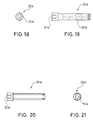
- Shifting unit 11a basically includes a first shift operating device 19a operatively coupled to rear derailleur 17 via first shift cable 20a, and a first gear indicator 21a operatively coupled to first shift operating device 19a by a first indicator cable 22a.
- shifting unit 11b basically includes a second shift operating device 19b operatively coupled to front derailleur 18 via second shift cable 20b, and a second gear indicator 21b operatively coupled to second shift operating device 19b by a second indicator cable 22b.
- Gear indicators 21a and 21b are adjustably mounted on handlebar 13 by a mounting device 23.
- shift operating devices 19a and 19b are substantially identical to each other, except that they are mirror images and have different numbers of gear shifting stages.
- first shift operating device 19a has six shifting stages
- second shift operating device 19b has three shifting stages. Since shift operating devices 19a and 19b are well known in the bicycle art and their particular constructions are not important to the present invention, shift operating devices 19a and 19b will not be discussed or illustrated in detail herein.
- each of the shift operating devices 19a and 19b has a take-up member (not shown).
- the take-up member of first shift operating device 19a is coupled to rear derailleur 17 via first shift cable 20a and to first gear indicator 21a by first indicator cable 22a.
- the take-up member of second shift operating device 19b is coupled to the front derailleur 18 via second shift cable 20b and to second gear indicator 21b by second indicator cable 22b.
- shift lever of either shift operating device 19a or 19b When a rider pushes the shift lever of either shift operating device 19a or 19b, this movement of the shift lever causes the corresponding take-up member to pivot about a rotational axis together with the shift lever. This movement of the shift lever also causes first or second shift cable 20a or 20b to be pulled and/or released so as to shift derailleur 17 or 18. Movement of the shift lever also causes indicator cable 22a or 22b to be released or pulled so that gear indicator 21a or 21b displays the current gear position of chain 16.
- first gear indicator 21a is substantially identical to second gear indicator 21b, except that they are substantial mirror images and have different numbers of shifting stages.
- the shifting stages of gear indicators 21a and 21b correspond to the number of shifting stages in shift operating devices 19a and 19b, respectively.
- first shift operating device 19a has six shift stages
- first gear indicator 21a has six gear indicating positions.
- second gear indicator 21b also has three gear indicating positions.
- mounting device 23 is illustrated for adjustably supporting first and second gear indicators 21a and 21b.
- Mounting device 23 is designed to allow shift operating devices 19a and 19b to be installed onto the outer ends of handlebars 13 and gear indicators 21a and 21b to be installed on the center section of handlebars 13.
- mounting device 23 is designed to accommodate various handlebars.
- Mounting device 23 adjustably supports gear indicators 21a and 21b such that gear indicators 21a and 21b can move in a direction that is substantially perpendicular to the vertical center plane of the bicycle. More specifically, mounting device 23 is designed to be mounted adjacent to the center of handlebar 13 with gear indicators 21a and 21b being slidably coupled thereto for movement generally along the longitudinal axis of handlebar 13.
- Mounting device 23 basically includes a pair of bar clamps 24a and 24b with a support member 25 adjustably coupled between bar clamps 24a and 24b. Gear indicators 21a and 21b are adjustably mounted on support member 25. Bar clamps 24a and 24b are substantially identical to each other, except that first bar clamp 24a is a mirror image of second bar clamp 24b.
- Each of the bar clamps 24a and 24b has a fastener 26a or 26b for fixedly securing bar clamps 24a and 24b to handlebar 13 of the bicycle and to support member 25.
- These fasteners 26a and 26b are preferably formed of a bolt 27a or 27b and a nut 28a or 28b.
- bar clamps 24a and 24b are preferably integrally formed as a one-piece, unitary member.
- Bar clamps 24a and 24b can be constructed of any suitable material that can be used to carry out the present invention.
- a lightweight material is utilized, such as plastic, or a lightweight metallic material.
- the right bar clamp 24a has a bar clamping portion 29a for attaching to handlebar 13, and a support portion 30a for adjustably supporting the support member 25.
- Bar clamping portion 29a has a split ring section 31a with one end of split ring section 31a coupled to support portion 30a by a connecting section 32a and the other end of split ring section 31a coupled to a free end section 33a.
- Split ring section 31a defines a mounting bore or hole 34a that is sized to receive a portion of handlebar 13 therein.
- Fastener 26a compresses connecting section 32a and free end section 33a towards each to adjust the size or diameter of mounting bore 34a of split ring section 31a to securely clamp handlebar 13 therein.
- connecting section 32a has a hole 37a that receives bolt 27a therethrough and free end section 33a has a slot 35a with nut 28a retained therein and a hole 36a that receives bolt 27a therethrough.
- nut 28a is frictionally retained in slot 35a of free end section 33a.
- Nut 28a is positioned to be coaxially located with hole 36a, such that bolt 27a can be threadedly coupled thereto.
- Support portion 30a also has a split ring section 41a with one end interconnected with bar clamping portion 29a by connecting section 32a and the other end of split ring section 41a having to a free end section 43a.
- Split ring section 41a defines a mounting bore or hole 44a with a ball joint 45a located therein. More specifically, mounting bore 44a of support portion 30a has a partial spherical surface 46a that allows ball joint 45a to rotate angularly therein.
- ball joint 45a is a split ring with a mounting bore 47a formed therein. Mounting bore 47a is sized to slidably receive support member 25 therein.
- the ball joint 45a When support member 25 is located within mounting bore 47a of ball joint 45a, the ball joint 45a preferably can move at least approximately twenty-five degrees from a center point where support member 25 has its longitudinal axis coincident with the longitudinal axis of mounting bore 44a of the support portion 30a.
- the free end section 43a of support portion 30a has a hole 48a for receiving bolt 27a of the fastener 26a therethrough.
- This hole 48a is aligned with hole 37a of connecting section 32a and hole 36a of free end section 33a. Accordingly, a single fastener is utilized to secure the bar clamp 24a to both handlebar 13 and support member 25.
- additional fasteners could be utilized.
- the bar clamping portion 29a and the support portion 30a could be constructed of several individual pieces.
- the left bar clamp 24b has a bar clamping portion 29b for attaching to handlebar 13, and a support portion 30b for adjustably supporting support member 25.
- Bar clamping portion 29b has a split ring section 31b with one end of split ring section 31b coupled to support portion 30b by connecting section 32b and the other end of split ring section 31b coupled to a free end section 33b.
- Split ring section 31b defines a mounting bore or hole 34b that is sized to receive a portion of handlebar 13 therein.
- Fastener 26b compresses connecting section 32b and free end section 33b towards each to adjust the size or diameter of mounting bore 34b of split ring section 31b to securely clamp handlebar 13 therein.
- connecting section 32b has a hole 37b that receives bolt 27b therethrough and free end section 33b has a slot 35b with nut 28b retained therein and a hole 36b that receives bolt 27b therethrough.
- nut 28b is frictionally retained in slot 35b of free end section 33b.
- Nut 28b is positioned to be coaxially located with hole 36b, such that bolt 27b can be threadedly coupled thereto.
- Support portion 30b also has a split ring section 41b with one end interconnected with bar clamping portion 29b by connecting section 32b and the other end of split ring section 41b having to a free end section 43b.
- Split ring section 41b defines a mounting bore or hole 44b with a ball joint 45b located therein. More specifically, mounting bore 44b of support portion 30b has a partial spherical surface 46b that allows ball joint 45b to rotate angularly therein.
- ball joint 45b is a split ring with a mounting bore 47b formed therein. Mounting bore 47b is sized to slidably receive support member 25 therein.
- the ball joint 45b preferably can move at least approximately twenty-five degrees from a center point where support member 25 has its longitudinal axis coincident with the longitudinal axis of mounting bore 44b of the support portion 30b.
- the free end section 43b of support portion 30b has a hole 48b for receiving bolt 27b of the fastener 26b therethrough.
- This hole 48b is aligned with hole 37b of connecting section 32b and hole 36b of free end section 33b. Accordingly, a single fastener is utilized to secure the bar clamp 24b to both handlebar 13 and support member 25.
- additional fasteners could be utilized.
- bar clamping portion 29b and support portion 30b could be constructed of several individual pieces.
- a rubber shim (not shown) can be placed within the mounting bores 34a and 34b of the bar clamping portions 29a and 29b to reduce the size of the mounting bores 34a and 34b of the bar clamping portions 29a and 29b to accommodate smaller diameter handlebar 13.
- support member 25 is preferably an elongated rod having a pair of rod sections 25a and 25b coupled together at their inner ends via a friction fit coupling. Accordingly, support member 25 allows the first and second bar clamps 24a and 24b to be utilized together as a single unit or to be separated and mounted at two spaced locations. Moreover, it will be apparent to those skilled in the art from this disclosure that additional rod sections could be added between these two rod sections 25a and 25b that are illustrated so as to lengthen the overall length of support member 25.
- each of these rod sections 25a and 25b is constructed of a lightweight material, such as plastic or a lightweight metallic material.
- each of the rod sections 25a and 25b has a non-circular cross-section so that when gear indicators 21a and 21b are mounted thereon, no rotation exists between gear indicators 21a and 21b and support member 25.
- rod sections 25a and 25b preferably have a partial curved cress-section with a flat side so as to be adjustable within ball joints 45a and 45b.
- a scale or positioning marks 50a and 50b are preferably formed along the longitudinal length of each of the rod sections 25a and 25b, so that gear indicators 21a and 21b can be precisely positioned in desired locations along support member 25 by the rider.
- each of the outer ends of rod sections 25a and 25b are provided with an annular recess for receiving an optional retaining clip (not shown) to prevent rod sections 25a and 25b from being accidentally uncoupled from bar clamps 24a and 24b.
- the inner ends of the rod sections 25a and 25b preferably have enlarged widths with the end surfaces having either a recess 51a or a protrusion 51b that mates with the adjoining rod section that has a corresponding recess 51a or protrusion 51b.
- first or right rod section 25a has a recess 51a
- second or left rod section 25b has a protrusion 51b.
- recess 51a and protrusion 51b are non-circular in cross-section to prevent relative rotation between rod sections 25a and 25b. Additionally, recess 51a and protrusion 51b preferably frictionally engage each other to prevent separation of rod sections 25a and 25b from each other.
- First or right gear indicator 21a is substantially identical to second or left gear indicator 21b, except that they are substantial mirror images and have different numbers of shifting stages.
- the shifting stages of gear indicators 21a and 21b correspond to the number of shifting stages in shift operating devices 19a and 19b, respectively.
- first shift operating device 19a has six shift stages
- first gear indicator 21a has six gear indicating positions.
- second shift operating device 19b has three shifting stage positions
- second gear indicator 21b also has three gear indicating positions.
- gear indicators 21a and 21b In view of the similarities between gear indicators 21a and 21b, it will be apparent to those skilled in the art from this disclosure that the construction and operation of second gear indicator 21b can be obtained from the description of first gear indicator 21a. Therefore, only first gear indicator 21a will be discussed or illustrated in detail herein.
- gear indicator 21a is constructed in such a manner that indicator- wire or cable 22a can be easily installed or replaced in a simple manner.
- Gear indicator 21a basically includes a housing 60a with a mounting portion 61a, a lid 62a detachably coupled to housing 60a and an internal indicator mechanism 63a.
- most of the parts of gear indicator 21a can be constructed of a lightweight plastic material. Of course, other types of suitable materials can also be utilized, such as lightweight metallic materials.
- lid 62a is releasably coupled to housing 60a by four fasteners or screws 64a ( Figure 3). Once lid 62a is removed, indicator wire or cable 22a can be easily installed or replaced without having to remove any additional fasteners.
- housing 60a and mounting portion 61a are preferably integrally formed together as a one-piece, unitary member.
- Housing 60a and mounting portion 61a can be constructed of a lightweight plastic material.
- suitable materials such as lightweight metallic materials.
- Mounting portion 61a preferably has a non-circular hole 64a that matches the non-circular cross-section of rod section 25a of support member 25 to slidably receive rod section 25a therein, but to prevent rotation therebetween.
- Mounting portion 61a also has a transverse threaded hole 65a with a set screw 66a to lock gear indicator 21a at a selected position along support member 25.
- mounting portion 61a can be a clamp with a split ring section similar in construction to the support portion of the bar clamp discussed above.
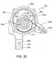
- Housing 60a has a cavity 67a for receiving internal indicator mechanism 63a therein, a front access opening 68a for accessing indicator mechanism 63a an indicator cable opening 69a in the side wall of housing 60a for receiving indicator cable 22a therethrough.
- Housing 60a has four holes for receiving lid mounting screws 64a.
- front opening 68a is closed by lid 62a.
- Cavity 67a of housing 60a has a step-shaped pivot shaft 70a with a threaded bore 71a and a discontinuous annular sleeve 72a that is coaxially mounted around pivot shaft 70a.
- Pivot shaft 70a and sleeve 72a rotatably support a portion of indicator mechanism 63a as explained below.
- Pivot shaft 70a has a first pivot axis A that is offset from the center or second pivot axis B of front access opening 68a so that indicator mechanism 63a can properly indicate the correct gear position, as explained below.
- the indicator cable opening 69a has its center longitudinal axis tangentially located relative to an imaginary circle positioned around the center axis A of pivot shaft 70a.
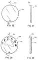
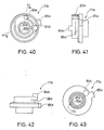
- lid 62a is preferably constructed of a molding portion or cover 73a ( Figures 34 and 35) and a transparent portion or lens 74a ( Figures 36-39).
- Cover 73a and lens 74a can be constructed of a lightweight plastic material. Of course, other types of suitable materials can also be utilized, such as lightweight metallic materials.
- Cover 73a is coupled to housing 60a by lid mounting screws 64a.
- Cover 73a has an opening or window 75a for viewing into the interior of housing 60a.
- Lens 74a is sandwiched between cover 73a and housing 60a and overlies opening or window 75a.
- lens 74a has a tab 76a that is received in a recess 73c in cover 73a so that lens 74a cannot rotate relative to mounting portion 61a as seen in Figure 26.
- Tab 76a also ensures correct orientation of lens 74a relative to cover 73a.
- lens 74a preferably has indicia printed thereon for indicating the gear positions.
- This indicia can be added directly to the inner surface of lens 74a, as shown, or to the external surface of lens 74a.
- This indicia can also be applied by a thin film 74c that is adhered to one of the inner or external surfaces of lens 74a.
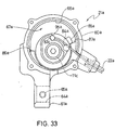
- indicator mechanism 63a basically includes an internal take-up element 77a, a coil spring 78a and an indicator plate 79a.
- Internal take-up element 77a and indicator plate 79a can each be constructed of a lightweight plastic material. Of course, other types of suitable materials can also be utilized, such as lightweight metallic materials.
- Internal take-up element 77a is rotatably secured to pivot shaft 70a of housing 60a via a threaded fastener 80a.
- internal take-up element 77a has a center hole 81a with an annular flange 82a that cooperates with the step-shape of pivot shaft 70a such that internal take-up element 77a can freely rotate therebetween.
- Internal take-up element 77a is coupled to housing 60a by a threaded fastener 71c.
- the front face of internal take-up element 77a that faces towards the front opening 68a has a circular recess 83a for receiving the nipple 95a of indicator cable 22a therein. Since the recess 83a is formed on the front face of internal take-up element 77a, the nipple 95a of indicator cable 22a can be easily inserted therein without having to detach internal take-up element 77a from housing 60a.
- the front face of internal take-up element 77a also has a circular protrusion 84a extending outwardly therefrom.
- This protrusion 84a is offset from the center axis A of internal take-up element 77a and is designed to engage indicator plate 79a for moving indicator plate 79a in response to movement of internal take-up element 77a, as explained below.
- internal take-up element 77a The pivotal or rotational movement of internal take-up element 77a is limited by a stop flange 85a that engages a pair of stops 86a and 87a formed on the inner surface of housing 60a.
- This stop flange 85a is located on the outer peripheral surface of internal take-up element 77a.
- the front face of internal take-up element 77a also has a cable retaining recess 88a that engages indicator cable 22a to hold the indicator cable 22a in place, and to prevent the nipple 95a from falling out of the recess 83a.
- coil spring 78a is a biasing member that biases internal take-up element 77a in a counter-clockwise direction as viewed looking into the cavity of housing 60a through the front opening 68a.
- internal take-up element 77a is biased so that the stop flange 85a engages the stop surface 86a.
- Coil spring 78a has a coiled portion 90a that is located around pivot shaft 70a and a pair of free ends 91a and 92a with free end 91a located in a recess 60c of housing 60a, and free ends 92a located in a spring retaining slot 77c of internal take-up element 77a.
- Coil spring 78a is set to be pre-loaded to hold internal take-up element 77a in the position, as seen in Figure 26.
- indicator plate 79a is generally a circular member that is rotatably mounted within the cavity of housing 60a about the center axis B of housing 60a. This center axis B of housing 60a is offset from the center axis A of pivot shaft 70a, as mentioned above.
- Indicator plate 79a includes indicia thereon for indicating the current gear position. More specifically, the indicia is a bar 79c that points to a number that is printed on lens 74a. In other words, indicator plate 79a rotates when the gear is shifted, such that indicator plate 79a rotates relative to lens 74a.
- Indicator plate 79a has a radially extending slot 93a that receives protrusion 84a of internal take-up element 77a. Accordingly, as internal take-up element 77a is rotated, protrusion 84a of internal take-up element 77a moves indicator plate 79a. Since the pivot axes of internal take-up element 77a and indicator plate 79a are not coincident with each other, indicator plate 79a does not rotate at the same speed as internal take-up element 77a.
Abstract
Description
Claims (13)
- A cable operated display device (21a) for a bicycle, comprising:a mounting portion (61a) adapted to be coupled to a portion of a bicycle;a housing (60a) coupled to said mounting portion (61a), said housing (60a) having an interior cavity (67a) and an open front (68a);an internal take-up element (77a) pivotally coupled within said housing (60a) about a first pivot axis (A), said internal take-up element (77a) having a cable attachment portion (83a) that is accessible through said open front (68a) of said housing without detaching said internal take-up element (77a) from said housing (60a); anda lid (62a) releasably coupled to said housing (60a) to overlie said open front (68a) of said housing (60a), said lid (62a) having a window (75a) to view movement of an indicator (79a) coupled to said internal take-up element (77a).
- A cable operated display device (21a) for a bicycle according to claim 1, wherein
said internal take-up element (77a) has front surface that faces said open front (68a) of said housing (60a), said cable attachment portion (83a) being a recess formed on said front surface of said internal take-up element (77a). - A cable operated display device (21a) for a bicycle according to claim 1 or 2, wherein
said internal take-up element (77a) is biasing in a rotational direction about said first pivot axis (A). - A cable operated display device (21a) for a bicycle according to any of the preceding claims, wherein
said indicator (79a) is pivotally coupled to said housing about a second pivot axis (B) that is offset from said first pivot axis (A) of said internal take-up element (77a). - A cable operated display device (21a) for a bicycle according to any of the preceding claims, wherein
said indicator (79a) has a slot (93a) with a pin of said internal take-up element (77a) located therein such that pivotally movement of said internal take-up element (77a) pivots said indicator (79a). - A cable operated display device (21a) for a bicycle according to any of the preceding claims, wherein
said lid (62a) includes a molding portion (73a) and an transparent portion (74a) overlying an opening in said molding portion to form said window (75a). - A cable operated display device (21a) for a bicycle according to any of the preceding claims, wherein
said mounting portion (61a) includes a clamp. - A cable operated display device (21a) for a bicycle according to any of the preceding claims, wherein
said clamp has a split ring section with a mounting bore and a fastener coupled to said split ring section to adjust the size of said mounting bore. - A cable operated display device (21a) for a bicycle according to any of the preceding claims, wherein
said lid (62a) is detachably coupled to said housing (60a) by at least one fastener. - A cable operated display device (21a) for a bicycle according to any of the preceding claims, wherein
said housing (60a) has a pivot shaft (70a) integrally formed therewith, said internal take-up element (77a) being pivotally supported on said pivot shaft (70a). - A cable operated display device (21a) for a bicycle according to any of the preceding claims, wherein
said internal take-up element (77a) is biasing in a rotational direction about said first pivot axis (A) by a coil spring (78a) mounted on said pivot shaft (70a). - A cable operated display device (21a) for a bicycle according to any of the preceding claims, wherein
said housing (60a) has a pair of stops (86a, 87a) integrally formed therewith that limits movement of said internal take-up element (77a). - A cable operated display device (21a) for a bicycle according to any of the preceding claims, wherein
said internal take-up element (77a) has a stop member (85a) that is located to selective engage said stops (86a, 87a) of said housing (60a).
Applications Claiming Priority (2)
| Application Number | Priority Date | Filing Date | Title |
|---|---|---|---|
| US09/516,023 US6265967B1 (en) | 2000-02-29 | 2000-02-29 | Display device for bicycle |
| US516023 | 2000-02-29 |
Publications (3)
| Publication Number | Publication Date |
|---|---|
| EP1129936A2 true EP1129936A2 (en) | 2001-09-05 |
| EP1129936A3 EP1129936A3 (en) | 2002-01-16 |
| EP1129936B1 EP1129936B1 (en) | 2005-03-30 |
Family
ID=24053790
Family Applications (1)
| Application Number | Title | Priority Date | Filing Date |
|---|---|---|---|
| EP01101547A Expired - Lifetime EP1129936B1 (en) | 2000-02-29 | 2001-01-24 | Display device for bicycle |
Country Status (6)
| Country | Link |
|---|---|
| US (1) | US6265967B1 (en) |
| EP (1) | EP1129936B1 (en) |
| JP (1) | JP3498060B2 (en) |
| CN (1) | CN1182000C (en) |
| DE (1) | DE60109666T2 (en) |
| TW (1) | TWI246488B (en) |
Families Citing this family (9)
| Publication number | Priority date | Publication date | Assignee | Title |
|---|---|---|---|---|
| US6332373B1 (en) * | 1999-02-16 | 2001-12-25 | Shimano Inc. | Gear indicator holder for a bicycle |
| US6394021B1 (en) * | 2000-12-13 | 2002-05-28 | Sram Corporation | Floating bicycle gear indicator |
| US6767064B2 (en) * | 2002-02-27 | 2004-07-27 | Lear Corporation | Translatable head restraint for automotive seat backrest |
| JP4246741B2 (en) | 2006-01-20 | 2009-04-02 | 株式会社キャットアイ | Display device |
| US8056438B2 (en) * | 2006-11-16 | 2011-11-15 | Shimano Components (Malaysia) Sdn. Bhd. | Bicycle shift control device |
| DE102013013187A1 (en) * | 2012-08-15 | 2014-02-20 | Marquardt Verwaltungs-Gmbh | Holder for a control and / or display unit |
| CN104743054B (en) * | 2015-03-21 | 2017-04-19 | 刘卫兵 | Twist grip type shifter for bicycle |
| US9797433B2 (en) * | 2015-06-30 | 2017-10-24 | Crank Brothers, Inc. | Remote control lever assembly |
| JP6927913B2 (en) * | 2018-03-28 | 2021-09-01 | 本田技研工業株式会社 | Meter stay support structure |
Citations (6)
| Publication number | Priority date | Publication date | Assignee | Title |
|---|---|---|---|---|
| US3524979A (en) | 1969-08-11 | 1970-08-18 | Seymour Cohen | Illuminated gearshift selector |
| JPS6023273U (en) | 1983-07-25 | 1985-02-18 | 藤井 孜 | Drip prevention device from the tip of the pump discharge pipe |
| US5052241A (en) | 1988-07-29 | 1991-10-01 | Shimano Industrial Co., Ltd. | Steering handle apparatus for use in bicycle |
| US5178033A (en) | 1991-09-03 | 1993-01-12 | August Kund | Bicycle gear display |
| EP0629860A1 (en) | 1993-06-16 | 1994-12-21 | Shimano Inc. | Display apparatus for a bicycle |
| US5458018A (en) | 1992-09-21 | 1995-10-17 | Shimano Inc. | Speed indicator for a shifting device of a bicycle |
Family Cites Families (7)
| Publication number | Priority date | Publication date | Assignee | Title |
|---|---|---|---|---|
| US2905017A (en) * | 1957-07-25 | 1959-09-22 | Allied Prod Corp | Bicycle transmission control |
| US3633437A (en) | 1969-07-31 | 1972-01-11 | Takuo Ishida | Hand control device for speed change gear mechanism of a bicycle |
| JP2602671Y2 (en) | 1992-01-21 | 2000-01-24 | 株式会社シマノ | Speed change device with display for bicycle |
| JPH0667291U (en) | 1993-03-09 | 1994-09-22 | 株式会社シマノ | Bicycle gear shift operation device |
| US5370412A (en) | 1993-08-10 | 1994-12-06 | Chou; Ming-Fu | Ergonomically superior bicycle meter assembly |
| JP3678496B2 (en) | 1996-05-30 | 2005-08-03 | 株式会社シマノ | Bicycle shifting operation device |
| JP3365910B2 (en) * | 1996-07-23 | 2003-01-14 | 株式会社シマノ | Bicycle display device |
-
2000
- 2000-02-29 US US09/516,023 patent/US6265967B1/en not_active Expired - Lifetime
- 2000-12-08 TW TW089126204A patent/TWI246488B/en not_active IP Right Cessation
-
2001
- 2001-01-11 CN CNB011013060A patent/CN1182000C/en not_active Expired - Fee Related
- 2001-01-24 DE DE60109666T patent/DE60109666T2/en not_active Expired - Fee Related
- 2001-01-24 EP EP01101547A patent/EP1129936B1/en not_active Expired - Lifetime
- 2001-02-23 JP JP2001048695A patent/JP3498060B2/en not_active Expired - Fee Related
Patent Citations (6)
| Publication number | Priority date | Publication date | Assignee | Title |
|---|---|---|---|---|
| US3524979A (en) | 1969-08-11 | 1970-08-18 | Seymour Cohen | Illuminated gearshift selector |
| JPS6023273U (en) | 1983-07-25 | 1985-02-18 | 藤井 孜 | Drip prevention device from the tip of the pump discharge pipe |
| US5052241A (en) | 1988-07-29 | 1991-10-01 | Shimano Industrial Co., Ltd. | Steering handle apparatus for use in bicycle |
| US5178033A (en) | 1991-09-03 | 1993-01-12 | August Kund | Bicycle gear display |
| US5458018A (en) | 1992-09-21 | 1995-10-17 | Shimano Inc. | Speed indicator for a shifting device of a bicycle |
| EP0629860A1 (en) | 1993-06-16 | 1994-12-21 | Shimano Inc. | Display apparatus for a bicycle |
Also Published As
| Publication number | Publication date |
|---|---|
| DE60109666T2 (en) | 2005-08-25 |
| DE60109666D1 (en) | 2005-05-04 |
| EP1129936B1 (en) | 2005-03-30 |
| TWI246488B (en) | 2006-01-01 |
| EP1129936A3 (en) | 2002-01-16 |
| JP2001270487A (en) | 2001-10-02 |
| CN1182000C (en) | 2004-12-29 |
| JP3498060B2 (en) | 2004-02-16 |
| CN1311124A (en) | 2001-09-05 |
| US6265967B1 (en) | 2001-07-24 |
Similar Documents
| Publication | Publication Date | Title |
|---|---|---|
| EP1129935B1 (en) | Mounting device for bicycle component | |
| EP1029778B1 (en) | Gear indicator for a bicycle | |
| EP1029780B1 (en) | Shift operating device | |
| US7448297B2 (en) | Mountable bicycle structure | |
| EP1129936B1 (en) | Display device for bicycle | |
| EP1481888B1 (en) | Bicycle shift control device | |
| EP1484240B1 (en) | Bicycle shift control device | |
| EP1029779B1 (en) | Gear indicator holder for a bicycle |
Legal Events
| Date | Code | Title | Description |
|---|---|---|---|
| PUAI | Public reference made under article 153(3) epc to a published international application that has entered the european phase |
Free format text: ORIGINAL CODE: 0009012 |
|
| AK | Designated contracting states |
Kind code of ref document: A2 Designated state(s): DE FR GB IE IT NL Kind code of ref document: A2 Designated state(s): AT BE CH CY DE DK ES FI FR GB GR IE IT LI LU MC NL PT SE TR |
|
| AX | Request for extension of the european patent |
Free format text: AL;LT;LV;MK;RO;SI |
|
| PUAL | Search report despatched |
Free format text: ORIGINAL CODE: 0009013 |
|
| AK | Designated contracting states |
Kind code of ref document: A3 Designated state(s): AT BE CH CY DE DK ES FI FR GB GR IE IT LI LU MC NL PT SE TR |
|
| AX | Request for extension of the european patent |
Free format text: AL;LT;LV;MK;RO;SI |
|
| 17P | Request for examination filed |
Effective date: 20020130 |
|
| AKX | Designation fees paid |
Free format text: DE FR GB IE IT NL |
|
| GRAP | Despatch of communication of intention to grant a patent |
Free format text: ORIGINAL CODE: EPIDOSNIGR1 |
|
| RAP1 | Party data changed (applicant data changed or rights of an application transferred) |
Owner name: SHIMANO INC. |
|
| GRAS | Grant fee paid |
Free format text: ORIGINAL CODE: EPIDOSNIGR3 |
|
| GRAA | (expected) grant |
Free format text: ORIGINAL CODE: 0009210 |
|
| AK | Designated contracting states |
Kind code of ref document: B1 Designated state(s): DE FR GB IE IT NL |
|
| REG | Reference to a national code |
Ref country code: GB Ref legal event code: FG4D |
|
| REF | Corresponds to: |
Ref document number: 60109666 Country of ref document: DE Date of ref document: 20050504 Kind code of ref document: P |
|
| REG | Reference to a national code |
Ref country code: IE Ref legal event code: FG4D |
|
| PG25 | Lapsed in a contracting state [announced via postgrant information from national office to epo] |
Ref country code: IE Free format text: LAPSE BECAUSE OF NON-PAYMENT OF DUE FEES Effective date: 20060124 |
|
| PLBE | No opposition filed within time limit |
Free format text: ORIGINAL CODE: 0009261 |
|
| STAA | Information on the status of an ep patent application or granted ep patent |
Free format text: STATUS: NO OPPOSITION FILED WITHIN TIME LIMIT |
|
| ET | Fr: translation filed | ||
| 26N | No opposition filed |
Effective date: 20060102 |
|
| REG | Reference to a national code |
Ref country code: IE Ref legal event code: MM4A |
|
| GBPC | Gb: european patent ceased through non-payment of renewal fee |
Effective date: 20070124 |
|
| PG25 | Lapsed in a contracting state [announced via postgrant information from national office to epo] |
Ref country code: GB Free format text: LAPSE BECAUSE OF NON-PAYMENT OF DUE FEES Effective date: 20070124 |
|
| PGFP | Annual fee paid to national office [announced via postgrant information from national office to epo] |
Ref country code: NL Payment date: 20080115 Year of fee payment: 8 |
|
| PGFP | Annual fee paid to national office [announced via postgrant information from national office to epo] |
Ref country code: GB Payment date: 20060123 Year of fee payment: 6 |
|
| PGFP | Annual fee paid to national office [announced via postgrant information from national office to epo] |
Ref country code: DE Payment date: 20090123 Year of fee payment: 9 |
|
| PGFP | Annual fee paid to national office [announced via postgrant information from national office to epo] |
Ref country code: IT Payment date: 20090130 Year of fee payment: 9 |
|
| NLV4 | Nl: lapsed or anulled due to non-payment of the annual fee |
Effective date: 20090801 |
|
| PGFP | Annual fee paid to national office [announced via postgrant information from national office to epo] |
Ref country code: FR Payment date: 20090113 Year of fee payment: 9 |
|
| PG25 | Lapsed in a contracting state [announced via postgrant information from national office to epo] |
Ref country code: NL Free format text: LAPSE BECAUSE OF NON-PAYMENT OF DUE FEES Effective date: 20090801 |
|
| REG | Reference to a national code |
Ref country code: FR Ref legal event code: ST Effective date: 20100930 |
|
| PG25 | Lapsed in a contracting state [announced via postgrant information from national office to epo] |
Ref country code: FR Free format text: LAPSE BECAUSE OF NON-PAYMENT OF DUE FEES Effective date: 20100201 |
|
| PG25 | Lapsed in a contracting state [announced via postgrant information from national office to epo] |
Ref country code: DE Free format text: LAPSE BECAUSE OF NON-PAYMENT OF DUE FEES Effective date: 20100803 |
|
| PG25 | Lapsed in a contracting state [announced via postgrant information from national office to epo] |
Ref country code: IT Free format text: LAPSE BECAUSE OF NON-PAYMENT OF DUE FEES Effective date: 20100124 |