EP1129870A2 - Pneumatic tires - Google Patents
Pneumatic tires Download PDFInfo
- Publication number
- EP1129870A2 EP1129870A2 EP01301712A EP01301712A EP1129870A2 EP 1129870 A2 EP1129870 A2 EP 1129870A2 EP 01301712 A EP01301712 A EP 01301712A EP 01301712 A EP01301712 A EP 01301712A EP 1129870 A2 EP1129870 A2 EP 1129870A2
- Authority
- EP
- European Patent Office
- Prior art keywords
- tire
- cord
- bead
- reinforcing layer
- radial direction
- Prior art date
- Legal status (The legal status is an assumption and is not a legal conclusion. Google has not performed a legal analysis and makes no representation as to the accuracy of the status listed.)
- Granted
Links
- 239000011324 bead Substances 0.000 claims abstract description 65
- 230000003014 reinforcing effect Effects 0.000 claims abstract description 49
- 239000000945 filler Substances 0.000 claims abstract description 14
- 230000002093 peripheral effect Effects 0.000 claims description 6
- 238000004804 winding Methods 0.000 claims description 3
- 206010016173 Fall Diseases 0.000 description 11
- 230000001965 increasing effect Effects 0.000 description 11
- 208000027418 Wounds and injury Diseases 0.000 description 7
- 238000005452 bending Methods 0.000 description 5
- 230000000052 comparative effect Effects 0.000 description 4
- 239000000835 fiber Substances 0.000 description 4
- 230000020169 heat generation Effects 0.000 description 4
- 230000015556 catabolic process Effects 0.000 description 3
- 238000006731 degradation reaction Methods 0.000 description 3
- 229910000831 Steel Inorganic materials 0.000 description 2
- 238000000926 separation method Methods 0.000 description 2
- 239000010959 steel Substances 0.000 description 2
- 230000015572 biosynthetic process Effects 0.000 description 1
- 238000010276 construction Methods 0.000 description 1
- 238000007796 conventional method Methods 0.000 description 1
- 230000003247 decreasing effect Effects 0.000 description 1
- 230000000694 effects Effects 0.000 description 1
- 230000002708 enhancing effect Effects 0.000 description 1
- 239000000446 fuel Substances 0.000 description 1
- 230000003252 repetitive effect Effects 0.000 description 1
- 230000000452 restraining effect Effects 0.000 description 1
- 238000005096 rolling process Methods 0.000 description 1
Images


Classifications
-
- B—PERFORMING OPERATIONS; TRANSPORTING
- B60—VEHICLES IN GENERAL
- B60C—VEHICLE TYRES; TYRE INFLATION; TYRE CHANGING; CONNECTING VALVES TO INFLATABLE ELASTIC BODIES IN GENERAL; DEVICES OR ARRANGEMENTS RELATED TO TYRES
- B60C15/00—Tyre beads, e.g. ply turn-up or overlap
- B60C15/06—Flipper strips, fillers, or chafing strips and reinforcing layers for the construction of the bead
-
- B—PERFORMING OPERATIONS; TRANSPORTING
- B60—VEHICLES IN GENERAL
- B60C—VEHICLE TYRES; TYRE INFLATION; TYRE CHANGING; CONNECTING VALVES TO INFLATABLE ELASTIC BODIES IN GENERAL; DEVICES OR ARRANGEMENTS RELATED TO TYRES
- B60C17/00—Tyres characterised by means enabling restricted operation in damaged or deflated condition; Accessories therefor
- B60C17/0009—Tyres characterised by means enabling restricted operation in damaged or deflated condition; Accessories therefor comprising sidewall rubber inserts, e.g. crescent shaped inserts
-
- B—PERFORMING OPERATIONS; TRANSPORTING
- B60—VEHICLES IN GENERAL
- B60C—VEHICLE TYRES; TYRE INFLATION; TYRE CHANGING; CONNECTING VALVES TO INFLATABLE ELASTIC BODIES IN GENERAL; DEVICES OR ARRANGEMENTS RELATED TO TYRES
- B60C15/00—Tyre beads, e.g. ply turn-up or overlap
- B60C15/06—Flipper strips, fillers, or chafing strips and reinforcing layers for the construction of the bead
- B60C15/0628—Flipper strips, fillers, or chafing strips and reinforcing layers for the construction of the bead comprising a bead reinforcing layer
- B60C2015/0639—Flipper strips, fillers, or chafing strips and reinforcing layers for the construction of the bead comprising a bead reinforcing layer between carcass main portion and bead filler not wrapped around the bead core
-
- Y—GENERAL TAGGING OF NEW TECHNOLOGICAL DEVELOPMENTS; GENERAL TAGGING OF CROSS-SECTIONAL TECHNOLOGIES SPANNING OVER SEVERAL SECTIONS OF THE IPC; TECHNICAL SUBJECTS COVERED BY FORMER USPC CROSS-REFERENCE ART COLLECTIONS [XRACs] AND DIGESTS
- Y10—TECHNICAL SUBJECTS COVERED BY FORMER USPC
- Y10T—TECHNICAL SUBJECTS COVERED BY FORMER US CLASSIFICATION
- Y10T152/00—Resilient tires and wheels
- Y10T152/10—Tires, resilient
- Y10T152/10495—Pneumatic tire or inner tube
- Y10T152/10855—Characterized by the carcass, carcass material, or physical arrangement of the carcass materials
- Y10T152/10864—Sidewall stiffening or reinforcing means other than main carcass plies or foldups thereof about beads
Definitions
- This invention relates to a pneumatic tire and more particularly to an improvement of a run-flat tire which can largely extend a runnable distance of the flat tire or a running distance at a run-flat state while controlling an increase of a tire weight.
- the increase of the volume in the members constituting the tire particularly increases the quantity of heat generation during the running under a high load fairly exceeding over the above lowered quantity of heat generation, which obstructs the extension of the running distance at the run-flat state and becomes a serious problem.
- an object of the invention to solve the aforementioned problems of the conventional technique and to provide a pneumatic tire capable of largely extending the running distance at the run-flat state under a high load by sufficiently enhancing the rigidity of the bead portion while advantageously controlling the increase of the tire weight.
- a pneumatic tire particularly a pneumatic radial tire comprising a tread portion, a pair of sidewall portions each extending inwardly from each side of the tread portion in a radial direction, a pair of bead portions each arranged at an inside of the sidewall portion in the radial direction, a carcass toroidally extending between a pair of bead cores each embedded in the respective bead portion and wound around the bead core from an inside of the tire toward an outside thereof in the radial direction to form a turnup portion, a bead filler arranged between a main body portion of the carcass and the turnup portion thereof and adjacent to an outer peripheral surface of the bead core, and a reinforcing rubber arranged at the inside of the sidewall portion in the widthwise direction of the tire and having substantially a crescent shape at cross section thereof, an improvement wherein at least one cord reinforcing layer made from a cord(s) extending in an angle direction of approximately 90
- section height of the tire used herein means a section height defined in JATMA YEAR BOOK and concretely means half the difference between the overall diameter and the nominal rim diameter when the tire is mounted onto an approved rim and inflated at the recommended air pressure under no load.
- radial line segment used herein means a plane including a rotating axis of the tire.
- the reinforcing rubber arranged at the inside of the sidewall portion and close to an inner face thereof mainly contributes to bear the weight of a vehicle body during the puncture of the tire to thereby control the expansion deformation of the sidewall portion in the widthwise direction, so that stress concentration into the sidewall portion and the carcass can advantageously be prevented during the puncture of the tire.
- the cord reinforcing layer is arranged at least in the bead portion, wherein the increase of the weight is fairly less as compared with the case of increasing the gauge of the reinforcing rubber and the thickness of the bead filler, whereby the rigidity of the bead portion against the falling-down during the running at the run-flat state under the high load can sufficiently be increased to largely extend the running distance at the run-flat state.
- a force restraining the expansion deformation can effectively be enhanced by increasing the gauge of the reinforcing rubber or increasing the number of the carcass plies, while the falling-down deformation of the bead portion under a working condition of a relatively low load can be countered by increasing the thickness of the bead filler or the number of the carcass plies.
- the falling-down deformation of the bead portion can not effectively be restrained when a higher load is applied to the tire, and the concentration of such a deformation in the bead portion can not be dispersed, and hence there is caused a fear of breaking a zone of the bead portion located in the vicinity of a rim flange.
- the cord reinforcing layer is arranged at least in the bead portion, whereby each of the falling-down deformation and the expansion deformation in a zone ranging from the bead portion to the sidewall portion is effectively controlled and the concentration of such deformations is prevented, so that the run-flat durability is largely improved even under the higher load without substantially increasing the gauge of the reinforcing rubber and the thickness of the bead filler.
- the cord reinforcing layer in such a tire functions to control the outward expansion deformation of the sidewall portion in the widthwise direction of the tire in the flat tire based on a high modulus of elasticity of the cord constituting the cord reinforcing layer and extending substantially in the circumferential direction of the tire, and to effectively restrain the outward falling-down of the carcass ply in the widthwise direction at least in the bead portion under a large cross angle between the cord in the cord reinforcing layer and the cord in the carcass ply, and to prevent separation between mutual cords in the carcass ply accompanied with the expansion deformation of the sidewall portion as mentioned above, and hence the weight of the vehicle body during the puncture of the tire can effectively be supported by the cord reinforcing layer.
- the cord constituting the cord reinforcing layer extends in an angle direction of approximately 90° with respect to the radial line segment, so that the cord is substantially continuous in the circumferential direction and can advantageously bear tension so as not to elongate in the circumferential direction. If the cord angle with respect to the radial line segment largely comes out from 90°, the cord becomes discontinuous in the circumferential direction and has free ends at the inside and outside in the radial direction, so that the above tension can not be born and the effect expected in the cord reinforcing layer can not sufficiently be developed and further the adhesion to the free end of the cord is insufficient to cause a fear of creating separation failure.
- the cord reinforcing layer according to the invention is formed by spirally winding a single cord or a bundle of plural cords arranged side by side.
- a joint part of the cord can be removed from the cord reinforcing layer to bear a larger tension in the circumferential direction, and hence the falling-down deformation of the bead portion can more effectively be restrained.
- the formation of the cord reinforcing layer can be more facilitated.
- the cord reinforcing layer may be formed by using a plurality of ring-shaped cords having different diameters.
- the width of the cord reinforcing layer in the radial direction of the tire is within a range of not less than 10% but not more than 50% of the section height of the tire.
- the width is not less than 10%, the rigidity can effectively be enhanced at least in the bead portion, preferably in a region ranging from the bead portion to the sidewall portion, while when the width is not more than 50%, the merit through the increase of the rigidity as compared with the increase of the tire weight can be ensured.
- the expansion deformation of the sidewall portion and the falling-down deformation of the bead portion are advantageously controlled under the action of the cord reinforcing layer without increasing the thickness of the bead filler and the gauge of the reinforcing rubber, whereby the effective extension of the running distance of the flat tire even under a higher load can be realized and also the increase of the tire weight can be controlled as small as possible.
- the cord constituting the cord reinforcing layer is an organic fiber cord or a steel cord and has a modulus of elasticity of not less than 3.2 GPa, and an end count of cords in the cord reinforcing layer per a width of 10 mm is 3-10 cords.
- the tire weight can effectively be decreased as compared with the case of using the steel cord.
- the rigidities of the bead portion and the sidewall portion can sufficiently be enhanced to sufficiently control the expansion deformation of the sidewall portion and the falling-down deformation of the bead portion in the running at the run-flat state even under a higher load after the puncture of the tire.
- the rigidities of the bead portion and the sidewall portion can sufficiently be enhanced, while when it is not more than 10 cords per 10 mm, the cord diameter can be ensured within an applicable range without extremely thinning it to advantageously enhance the rigidity of each respective portion.
- Fig. 1 a diagrammatically section view of an embodiment of the pneumatic radial tire according to the invention at a state of assembling onto a rim and inflating under an air pressure, in which numeral 1 is a tread portion, numeral 2 a sidewall portion continuously extending inward from each side of the tread portion in a radial direction, and numeral 3 a bead portion continuously arranged at an inner peripheral side of the sidewall portion.
- rim and "air pressure” used herein mean an approved rim and a maximum air pressure defined in JATMA YEAR BOOK, respectively.
- a radial carcass 5 comprised of at least one carcass ply is toroidally extended between a pair of bead cores 4 each embedded in the respective bead portion 3 to reinforce the above portions 1, 2 and 3, and wound around the bead core 4 from an inside of the tire toward outside thereof in a widthwise direction to form a turnup portion
- a belt 6 comprised of at least one belt layer, two belt layers in Fig. 1, is arranged at an outer peripheral side of a crown portion of the radial carcass 5.
- a bead filler 7 having substantially a triangular shape in its cross section is arranged between a main body portion and a turnup portion of the radial carcass 6 and adjacent to an outer peripheral side of the bead core 4, and a reinforcing rubber 8 having substantially a crescent shape in its cross section is mainly arranged at an inside of the sidewall portion 2 in the widthwise direction of the tire.
- a cord reinforcing layer 9 having a spirally wound structure of a cord preferably, an organic fiber cord extending in an angle direction of approximately 90° with respect to a radial line segment is arranged within a region ranging outward from the vicinity of the bead core 4 and inward from a turnup end of the radial carcass 5 in the radial direction and, for example, between the main body portion of the radial carcass 5 and the bead filler 7 in the illustrated embodiment.
- the cord reinforcing layer 9 is formed by spirally winding a single cord or a bundle of plural cord as shown in Fig. 2.
- the cord reinforcing layer 9 may be arranged between the turnup portion of the radial carcass 5 and the bead filler 7, or may be arranged inside the main body portion of the radial carcass 5 or outside the turnup portion thereof in the widthwise direction.
- the cord reinforcing layer 9 has a width in the radial direction of the tire corresponding to 10-50% of a section height SH of the tire. And also, the cord reinforcing layer 9 is an organic fiber cord having a modulus of elasticity of not less than 3.2 GPa, and an end count of cords in the cord reinforcing layer 9 is 3-10 cords per 10 mm.
- the weight of the vehicle body can effectively be supported by the cord reinforcing layer 9 in addition to the reinforcing rubber 8, the bead filler 7 and the radial carcass 5 during the running of the tire at the run-flat state as mentioned above, so that the rigidities of the sidewall portion and the bead portion can sufficiently be enhanced even at a higher load under a slight increase of the weight resulted from the addition of the cord reinforcing layer 9 without substantially increasing the gauge of the reinforcing rubber 8 and the thickness of the bead filler 7 and without increasing the number of the carcass plies, and hence the running distance of the flat tire can largely be extended.
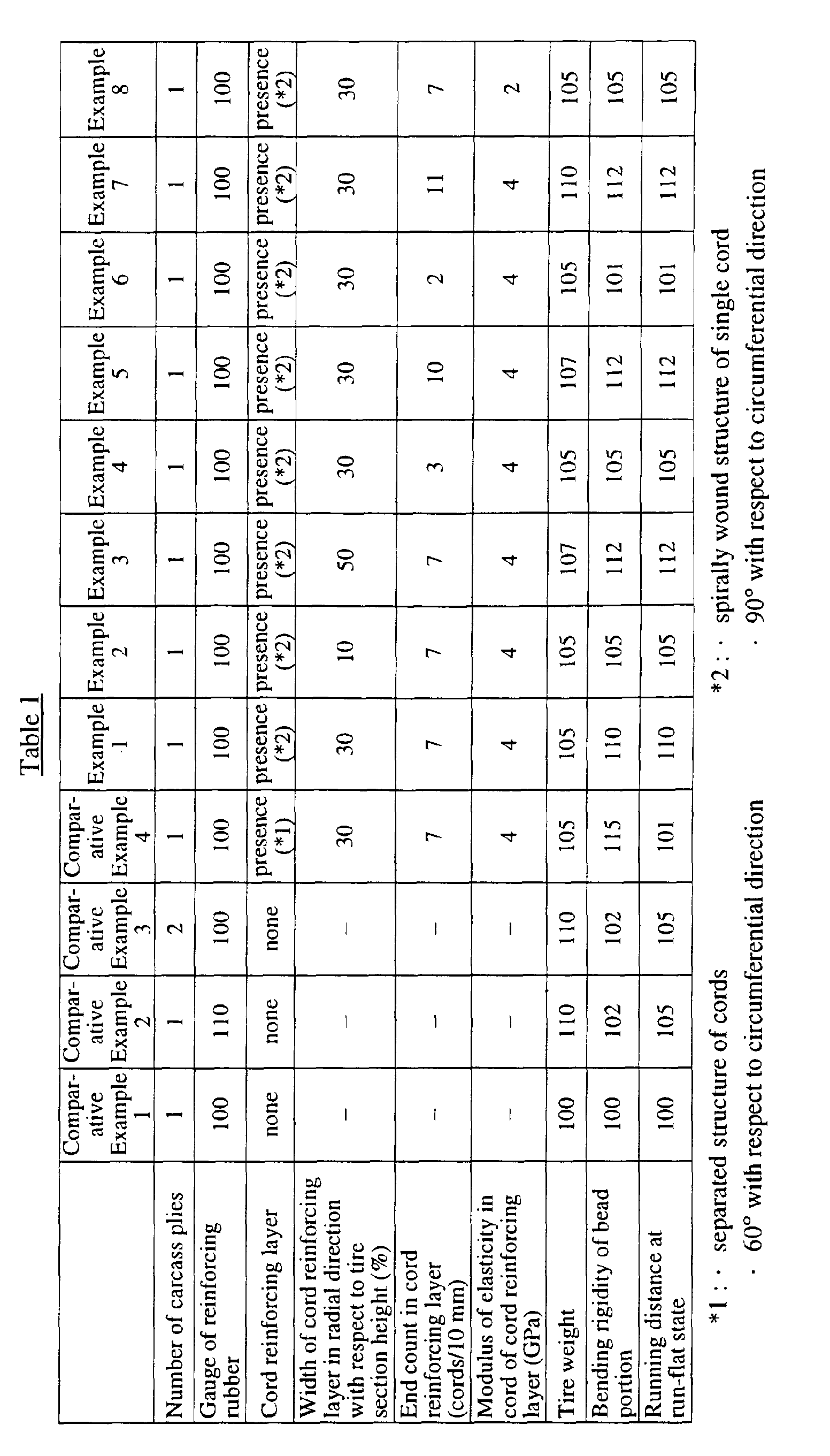
- tires of Examples 1-8 and Comparative Examples 1-4 are measured modulus of elasticity of cord constituting cord reinforcing layer, tire weight, rigidity to falling-down deformation of bead portion or bending rigidity, and running distance of the flat tire.
- Each of the above tires has a tire size of 225/60R16.
- the example tires have a structure shown in Fig. 1 and the comparative tires have such a structure that the cord reinforcing layer is omitted from Fig. 1.
- the cord reinforcing layers in all example tires has a spirally wound structure of a single cord.
- the tire weight is directly measured from the tire.
- the bending rigidity of the bead portion is evaluated by grasping a part of the bead portion and applying a constant weight to another part of the bead portion opposite to the above part with respect to a center of a circumference to measure a deformation quantity and then calculating a reciprocal number from the measured value.
- the running distance of the flat tire is evaluated by measuring a distance run on an oval circuit course at a speed of 100 km/h until the occurrence of trouble in a front left-wheeled tire among the tires mounted onto a passenger car at a state that a valve core is get out from the front left-wheeled tire and the other tires are inflated under a given air pressure.
- the expansion deformation of the sidewall portion and the falling-down deformation of the bead portion can effectively be controlled to largely extend the running distance of the flat tire under an action of the cord reinforcing layer without increasing the gauge of the reinforcing rubber and the thickness of the bead filler and the number of carcass plies and the like, that is, even by effectively controlling the increase of the tire weight.
Landscapes
- Engineering & Computer Science (AREA)
- Mechanical Engineering (AREA)
- Tires In General (AREA)
- Yarns And Mechanical Finishing Of Yarns Or Ropes (AREA)
Abstract
Description
Claims (4)
- A pneumatic tire comprising a tread portion (1), a pair of sidewall portions (2) each extending inwardly from each side of the tread portion in a radial direction, a pair of bead portions (3) each arranged at an inside of the sidewall portion in the radial direction, a carcass (5) toroidally extending between a pair of bead cores (4) each embedded in a respective bead portion and wound around the bead core from the inside of the tire toward the outside thereof in the radial direction to form a turnup portion, a bead filler (7) arranged between a main body portion of the carcass (5) and the turnup portion thereof and adjacent to an outer peripheral surface of the bead core (4), and a reinforcing rubber (8) arranged at the inside of the sidewall portion (2) in the widthwise direction of the tire and having substantially a crescent shape in cross section thereof, characterized in that at least one cord reinforcing layer (9) made from a cord(s) extending in an angle direction of approximately 90° with respect to a radial line segment is arranged in a region ranging outward from the vicinity of the bead core (4) in the radial direction and has a width in the radial direction of the tire corresponding to 10-50% of a section height (SH) of the tire.
- A pneumatic tire as claimed in claim 1, characterized in that the cord constituting the cord reinforcing layer (9) has a modulus of elasticity of not less than 3.2 GPa.
- A pneumatic tire as claimed in claim 1 or 2, characterized in that an end count of cords in the cord reinforcing layer (9) per a width of 10 mm is 3-10 cords.
- A pneumatic tire as claimed in any of claims 1 to 3, characterized in that the cord reinforcing layer (9) is formed by spirally winding a single cord or a bundle of plural cords arranged side by side.
Applications Claiming Priority (2)
| Application Number | Priority Date | Filing Date | Title |
|---|---|---|---|
| JP2000054054A JP2001239813A (en) | 2000-02-29 | 2000-02-29 | Pneumatic tire |
| JP2000054054 | 2000-02-29 |
Publications (3)
| Publication Number | Publication Date |
|---|---|
| EP1129870A2 true EP1129870A2 (en) | 2001-09-05 |
| EP1129870A3 EP1129870A3 (en) | 2003-04-16 |
| EP1129870B1 EP1129870B1 (en) | 2005-09-14 |
Family
ID=18575360
Family Applications (1)
| Application Number | Title | Priority Date | Filing Date |
|---|---|---|---|
| EP01301712A Expired - Lifetime EP1129870B1 (en) | 2000-02-29 | 2001-02-26 | Pneumatic tires |
Country Status (5)
| Country | Link |
|---|---|
| US (1) | US6543502B2 (en) |
| EP (1) | EP1129870B1 (en) |
| JP (1) | JP2001239813A (en) |
| DE (1) | DE60113321T2 (en) |
| ES (1) | ES2248238T3 (en) |
Cited By (6)
| Publication number | Priority date | Publication date | Assignee | Title |
|---|---|---|---|---|
| EP1174289A3 (en) * | 2000-07-05 | 2003-08-27 | Bridgestone Corporation | Pneumatic tire |
| WO2005090100A1 (en) * | 2004-02-20 | 2005-09-29 | Continental Aktiengesellschaft | Motor vehicle pneumatic tires and method for the production thereof |
| WO2007003246A1 (en) | 2005-07-01 | 2007-01-11 | Continental Aktiengesellschaft | Vehicle tyre comprising a reinforced thickened construction |
| WO2007141073A1 (en) * | 2006-06-02 | 2007-12-13 | Continental Aktiengesellschaft | Vehicle pneumatic tire with run-flat characteristics |
| WO2010057523A1 (en) * | 2008-11-18 | 2010-05-27 | Pirelli Tyre S.P.A. | Pneumatic vehicle tire |
| CN110014789A (en) * | 2017-12-15 | 2019-07-16 | 固特异轮胎和橡胶公司 | Pneumatic tire with solid bead area structure |
Families Citing this family (10)
| Publication number | Priority date | Publication date | Assignee | Title |
|---|---|---|---|---|
| JP2002103914A (en) * | 2000-07-25 | 2002-04-09 | Bridgestone Corp | Pneumatic radial tire |
| JP4493353B2 (en) * | 2004-01-23 | 2010-06-30 | 株式会社ブリヂストン | Run flat tire |
| JP4734028B2 (en) * | 2005-05-17 | 2011-07-27 | 株式会社ブリヂストン | Pneumatic tire |
| DE102006011158A1 (en) * | 2006-03-10 | 2007-09-13 | Continental Aktiengesellschaft | Vehicle tires |
| JP4971700B2 (en) * | 2006-06-26 | 2012-07-11 | 住友ゴム工業株式会社 | Run flat tire |
| JP2008155866A (en) * | 2006-12-26 | 2008-07-10 | Bridgestone Corp | Pneumatic tire and vehicle with the same |
| CN106739842A (en) * | 2017-01-11 | 2017-05-31 | 赛轮金宇集团股份有限公司 | Run-flat tire |
| JP7142556B2 (en) * | 2018-12-13 | 2022-09-27 | 株式会社ブリヂストン | pneumatic tire |
| CN111559208A (en) * | 2020-04-14 | 2020-08-21 | 安徽佳通乘用子午线轮胎有限公司 | Special inflatable radial tire for overtravel race |
| US20230191839A1 (en) * | 2021-12-17 | 2023-06-22 | The Goodyear Tire & Rubber Company | Pneumatic tire |
Family Cites Families (8)
| Publication number | Priority date | Publication date | Assignee | Title |
|---|---|---|---|---|
| FR1234995A (en) * | 1958-09-05 | 1960-07-01 | Dunlop Sa | Improvements to pneumatic tires |
| IT1160797B (en) * | 1983-04-18 | 1987-03-11 | Pirelli | SELF-SUPPORTING TIRE |
| JPS6181805A (en) * | 1984-09-29 | 1986-04-25 | Yokohama Rubber Co Ltd:The | Radial tire for passenger car |
| US5368082A (en) * | 1992-09-30 | 1994-11-29 | The Goodyear Tire & Rubber Company | Radial ply pneumatic tire |
| FR2718390A1 (en) * | 1994-04-11 | 1995-10-13 | Michelin & Cie | Pneumatic with reinforced sidewalls. |
| FR2730190B1 (en) * | 1995-02-02 | 1997-04-18 | Michelin & Cie | TIRE SADDLES |
| US6209604B1 (en) * | 1997-12-22 | 2001-04-03 | Bridgestone Corporation | Pneumatic tire for passenger cars with sidewall portions having a rubber reinforcing layer and a rubber-filament fiber composite |
| JP2001080318A (en) * | 1999-09-10 | 2001-03-27 | Bridgestone Corp | Pneumatic tire |
-
2000
- 2000-02-29 JP JP2000054054A patent/JP2001239813A/en active Pending
-
2001
- 2001-02-26 EP EP01301712A patent/EP1129870B1/en not_active Expired - Lifetime
- 2001-02-26 DE DE60113321T patent/DE60113321T2/en not_active Expired - Fee Related
- 2001-02-26 ES ES01301712T patent/ES2248238T3/en not_active Expired - Lifetime
- 2001-02-28 US US09/793,906 patent/US6543502B2/en not_active Expired - Lifetime
Cited By (7)
| Publication number | Priority date | Publication date | Assignee | Title |
|---|---|---|---|---|
| EP1174289A3 (en) * | 2000-07-05 | 2003-08-27 | Bridgestone Corporation | Pneumatic tire |
| US6776207B2 (en) | 2000-07-05 | 2004-08-17 | Bridgestone Corporation | Pneumatic tire with bead reinforcing layer adjacent bead filler |
| WO2005090100A1 (en) * | 2004-02-20 | 2005-09-29 | Continental Aktiengesellschaft | Motor vehicle pneumatic tires and method for the production thereof |
| WO2007003246A1 (en) | 2005-07-01 | 2007-01-11 | Continental Aktiengesellschaft | Vehicle tyre comprising a reinforced thickened construction |
| WO2007141073A1 (en) * | 2006-06-02 | 2007-12-13 | Continental Aktiengesellschaft | Vehicle pneumatic tire with run-flat characteristics |
| WO2010057523A1 (en) * | 2008-11-18 | 2010-05-27 | Pirelli Tyre S.P.A. | Pneumatic vehicle tire |
| CN110014789A (en) * | 2017-12-15 | 2019-07-16 | 固特异轮胎和橡胶公司 | Pneumatic tire with solid bead area structure |
Also Published As
| Publication number | Publication date |
|---|---|
| JP2001239813A (en) | 2001-09-04 |
| US6543502B2 (en) | 2003-04-08 |
| DE60113321D1 (en) | 2005-10-20 |
| DE60113321T2 (en) | 2006-06-29 |
| ES2248238T3 (en) | 2006-03-16 |
| EP1129870A3 (en) | 2003-04-16 |
| US20010022210A1 (en) | 2001-09-20 |
| EP1129870B1 (en) | 2005-09-14 |
Similar Documents
| Publication | Publication Date | Title |
|---|---|---|
| JP3645277B2 (en) | Pneumatic tire | |
| EP1129870B1 (en) | Pneumatic tires | |
| US11338622B2 (en) | Run-flat tire | |
| EP1837205B1 (en) | Pneumatic tire | |
| US6938659B2 (en) | Runflat tire having crown-reinforcing insert extending into the sidewalls | |
| JPWO2002042094A1 (en) | Pneumatic safety tire | |
| EP1083065B1 (en) | Pneumatic tire | |
| JP3993889B2 (en) | Pneumatic radial tire | |
| US6719029B2 (en) | Tire wall gauges to optimize runflat tire ride comfort | |
| US20210094363A1 (en) | Sidewall construction for a tire | |
| EP1116605A2 (en) | Pneumatic tire | |
| JP3157602B2 (en) | Runflat pneumatic radial tires | |
| JP3364256B2 (en) | Pneumatic tire | |
| JP3971831B2 (en) | Pneumatic tire | |
| JP2006076431A (en) | Run flat tire | |
| JP4658377B2 (en) | Radial tires for motorcycles | |
| EP1055530B1 (en) | Pneumatic tires | |
| JP4315647B2 (en) | Pneumatic tire | |
| JP3730618B2 (en) | Pneumatic tire | |
| JP5522708B2 (en) | Pneumatic tire | |
| JP5288543B2 (en) | Pneumatic radial tire | |
| JP4334945B2 (en) | Pneumatic tire | |
| EP4159487B1 (en) | Wraparound structure for a belt package of a tire | |
| JP4315646B2 (en) | Pneumatic tire | |
| JP7306215B2 (en) | pneumatic tire |
Legal Events
| Date | Code | Title | Description |
|---|---|---|---|
| PUAI | Public reference made under article 153(3) epc to a published international application that has entered the european phase |
Free format text: ORIGINAL CODE: 0009012 |
|
| AK | Designated contracting states |
Kind code of ref document: A2 Designated state(s): AT BE CH CY DE DK ES FI FR GB GR IE IT LI LU MC NL PT SE TR |
|
| AX | Request for extension of the european patent |
Free format text: AL;LT;LV;MK;RO;SI |
|
| RIN1 | Information on inventor provided before grant (corrected) |
Inventor name: OHURA, KENICHI C/O BRIDGESTONE TECHNICAL CENTRE |
|
| PUAL | Search report despatched |
Free format text: ORIGINAL CODE: 0009013 |
|
| AK | Designated contracting states |
Designated state(s): AT BE CH CY DE DK ES FI FR GB GR IE IT LI LU MC NL PT SE TR |
|
| AX | Request for extension of the european patent |
Extension state: AL LT LV MK RO SI |
|
| 17P | Request for examination filed |
Effective date: 20030325 |
|
| AKX | Designation fees paid |
Designated state(s): DE ES FR GB IT |
|
| 17Q | First examination report despatched |
Effective date: 20040611 |
|
| GRAP | Despatch of communication of intention to grant a patent |
Free format text: ORIGINAL CODE: EPIDOSNIGR1 |
|
| GRAS | Grant fee paid |
Free format text: ORIGINAL CODE: EPIDOSNIGR3 |
|
| GRAA | (expected) grant |
Free format text: ORIGINAL CODE: 0009210 |
|
| AK | Designated contracting states |
Kind code of ref document: B1 Designated state(s): DE ES FR GB IT |
|
| REG | Reference to a national code |
Ref country code: GB Ref legal event code: FG4D |
|
| REF | Corresponds to: |
Ref document number: 60113321 Country of ref document: DE Date of ref document: 20051020 Kind code of ref document: P |
|
| PGFP | Annual fee paid to national office [announced via postgrant information from national office to epo] |
Ref country code: FR Payment date: 20060220 Year of fee payment: 6 |
|
| PGFP | Annual fee paid to national office [announced via postgrant information from national office to epo] |
Ref country code: DE Payment date: 20060223 Year of fee payment: 6 |
|
| PGFP | Annual fee paid to national office [announced via postgrant information from national office to epo] |
Ref country code: IT Payment date: 20060228 Year of fee payment: 6 |
|
| REG | Reference to a national code |
Ref country code: ES Ref legal event code: FG2A Ref document number: 2248238 Country of ref document: ES Kind code of ref document: T3 |
|
| PGFP | Annual fee paid to national office [announced via postgrant information from national office to epo] |
Ref country code: ES Payment date: 20060317 Year of fee payment: 6 |
|
| ET | Fr: translation filed | ||
| PLBE | No opposition filed within time limit |
Free format text: ORIGINAL CODE: 0009261 |
|
| STAA | Information on the status of an ep patent application or granted ep patent |
Free format text: STATUS: NO OPPOSITION FILED WITHIN TIME LIMIT |
|
| 26N | No opposition filed |
Effective date: 20060615 |
|
| GBPC | Gb: european patent ceased through non-payment of renewal fee |
Effective date: 20070226 |
|
| REG | Reference to a national code |
Ref country code: FR Ref legal event code: ST Effective date: 20071030 |
|
| PG25 | Lapsed in a contracting state [announced via postgrant information from national office to epo] |
Ref country code: DE Free format text: LAPSE BECAUSE OF NON-PAYMENT OF DUE FEES Effective date: 20070901 |
|
| PG25 | Lapsed in a contracting state [announced via postgrant information from national office to epo] |
Ref country code: GB Free format text: LAPSE BECAUSE OF NON-PAYMENT OF DUE FEES Effective date: 20070226 Ref country code: FR Free format text: LAPSE BECAUSE OF NON-PAYMENT OF DUE FEES Effective date: 20070228 |
|
| REG | Reference to a national code |
Ref country code: ES Ref legal event code: FD2A Effective date: 20070227 |
|
| PG25 | Lapsed in a contracting state [announced via postgrant information from national office to epo] |
Ref country code: ES Free format text: LAPSE BECAUSE OF NON-PAYMENT OF DUE FEES Effective date: 20070227 |
|
| PGFP | Annual fee paid to national office [announced via postgrant information from national office to epo] |
Ref country code: GB Payment date: 20060222 Year of fee payment: 6 |
|
| PG25 | Lapsed in a contracting state [announced via postgrant information from national office to epo] |
Ref country code: IT Free format text: LAPSE BECAUSE OF NON-PAYMENT OF DUE FEES Effective date: 20070226 |