EP1129760A2 - Integrally molded filter unit and method for manufacturing the same - Google Patents
Integrally molded filter unit and method for manufacturing the same Download PDFInfo
- Publication number
- EP1129760A2 EP1129760A2 EP01104505A EP01104505A EP1129760A2 EP 1129760 A2 EP1129760 A2 EP 1129760A2 EP 01104505 A EP01104505 A EP 01104505A EP 01104505 A EP01104505 A EP 01104505A EP 1129760 A2 EP1129760 A2 EP 1129760A2
- Authority
- EP
- European Patent Office
- Prior art keywords
- filter
- holding frame
- filtration material
- filter unit
- thickness
- Prior art date
- Legal status (The legal status is an assumption and is not a legal conclusion. Google has not performed a legal analysis and makes no representation as to the accuracy of the status listed.)
- Granted
Links
- 238000000034 method Methods 0.000 title claims description 56
- 238000004519 manufacturing process Methods 0.000 title claims description 29
- 239000000463 material Substances 0.000 claims abstract description 105
- 238000001914 filtration Methods 0.000 claims abstract description 102
- 229920005992 thermoplastic resin Polymers 0.000 claims abstract description 15
- 239000003463 adsorbent Substances 0.000 claims abstract description 13
- 229920002725 thermoplastic elastomer Polymers 0.000 claims description 13
- 238000001746 injection moulding Methods 0.000 claims description 12
- 150000001336 alkenes Chemical class 0.000 claims description 8
- JRZJOMJEPLMPRA-UHFFFAOYSA-N olefin Natural products CCCCCCCC=C JRZJOMJEPLMPRA-UHFFFAOYSA-N 0.000 claims description 8
- 229920001971 elastomer Polymers 0.000 claims description 3
- 239000000806 elastomer Substances 0.000 claims description 3
- 238000005304 joining Methods 0.000 claims description 3
- 229920005989 resin Polymers 0.000 description 40
- 239000011347 resin Substances 0.000 description 40
- OKTJSMMVPCPJKN-UHFFFAOYSA-N Carbon Chemical compound [C] OKTJSMMVPCPJKN-UHFFFAOYSA-N 0.000 description 30
- 238000009434 installation Methods 0.000 description 19
- 239000000428 dust Substances 0.000 description 18
- 230000015572 biosynthetic process Effects 0.000 description 16
- YXFVVABEGXRONW-UHFFFAOYSA-N Toluene Chemical compound CC1=CC=CC=C1 YXFVVABEGXRONW-UHFFFAOYSA-N 0.000 description 15
- 238000000465 moulding Methods 0.000 description 15
- 230000000052 comparative effect Effects 0.000 description 13
- 230000003247 decreasing effect Effects 0.000 description 9
- -1 poly(vinyl chloride) Polymers 0.000 description 8
- 230000002950 deficient Effects 0.000 description 7
- 238000003780 insertion Methods 0.000 description 5
- 230000037431 insertion Effects 0.000 description 5
- 239000004743 Polypropylene Substances 0.000 description 4
- 238000001816 cooling Methods 0.000 description 4
- 238000002347 injection Methods 0.000 description 4
- 239000007924 injection Substances 0.000 description 4
- 238000005259 measurement Methods 0.000 description 4
- 229920001155 polypropylene Polymers 0.000 description 4
- 238000000926 separation method Methods 0.000 description 4
- 238000011144 upstream manufacturing Methods 0.000 description 4
- 239000002245 particle Substances 0.000 description 3
- 229920000728 polyester Polymers 0.000 description 3
- PPBRXRYQALVLMV-UHFFFAOYSA-N Styrene Chemical compound C=CC1=CC=CC=C1 PPBRXRYQALVLMV-UHFFFAOYSA-N 0.000 description 2
- 230000000740 bleeding effect Effects 0.000 description 2
- 230000007547 defect Effects 0.000 description 2
- 239000003365 glass fiber Substances 0.000 description 2
- 239000000843 powder Substances 0.000 description 2
- 238000003825 pressing Methods 0.000 description 2
- 230000003014 reinforcing effect Effects 0.000 description 2
- 238000012360 testing method Methods 0.000 description 2
- 238000009423 ventilation Methods 0.000 description 2
- 239000004925 Acrylic resin Substances 0.000 description 1
- 229920000178 Acrylic resin Polymers 0.000 description 1
- 239000004215 Carbon black (E152) Substances 0.000 description 1
- JOYRKODLDBILNP-UHFFFAOYSA-N Ethyl urethane Chemical compound CCOC(N)=O JOYRKODLDBILNP-UHFFFAOYSA-N 0.000 description 1
- 229920000877 Melamine resin Polymers 0.000 description 1
- 239000004952 Polyamide Substances 0.000 description 1
- XUIMIQQOPSSXEZ-UHFFFAOYSA-N Silicon Chemical compound [Si] XUIMIQQOPSSXEZ-UHFFFAOYSA-N 0.000 description 1
- BZHJMEDXRYGGRV-UHFFFAOYSA-N Vinyl chloride Chemical compound ClC=C BZHJMEDXRYGGRV-UHFFFAOYSA-N 0.000 description 1
- 239000000853 adhesive Substances 0.000 description 1
- 230000001070 adhesive effect Effects 0.000 description 1
- 230000004075 alteration Effects 0.000 description 1
- 210000000078 claw Anatomy 0.000 description 1
- 238000010924 continuous production Methods 0.000 description 1
- 238000007796 conventional method Methods 0.000 description 1
- 238000009826 distribution Methods 0.000 description 1
- 239000003822 epoxy resin Substances 0.000 description 1
- 238000011156 evaluation Methods 0.000 description 1
- 239000004744 fabric Substances 0.000 description 1
- 125000001153 fluoro group Chemical group F* 0.000 description 1
- LNEPOXFFQSENCJ-UHFFFAOYSA-N haloperidol Chemical compound C1CC(O)(C=2C=CC(Cl)=CC=2)CCN1CCCC(=O)C1=CC=C(F)C=C1 LNEPOXFFQSENCJ-UHFFFAOYSA-N 0.000 description 1
- 229930195733 hydrocarbon Natural products 0.000 description 1
- 150000002430 hydrocarbons Chemical class 0.000 description 1
- 238000011835 investigation Methods 0.000 description 1
- 238000000691 measurement method Methods 0.000 description 1
- 238000002844 melting Methods 0.000 description 1
- 230000008018 melting Effects 0.000 description 1
- 238000012986 modification Methods 0.000 description 1
- 230000004048 modification Effects 0.000 description 1
- 239000004745 nonwoven fabric Substances 0.000 description 1
- 238000012856 packing Methods 0.000 description 1
- 239000005011 phenolic resin Substances 0.000 description 1
- 229920002647 polyamide Polymers 0.000 description 1
- 229920000647 polyepoxide Polymers 0.000 description 1
- 229920001225 polyester resin Polymers 0.000 description 1
- 239000004645 polyester resin Substances 0.000 description 1
- 229920000642 polymer Polymers 0.000 description 1
- 229920005672 polyolefin resin Polymers 0.000 description 1
- 229920005990 polystyrene resin Polymers 0.000 description 1
- 229920005749 polyurethane resin Polymers 0.000 description 1
- 239000011118 polyvinyl acetate Substances 0.000 description 1
- 229920002689 polyvinyl acetate Polymers 0.000 description 1
- 229920000915 polyvinyl chloride Polymers 0.000 description 1
- 239000004800 polyvinyl chloride Substances 0.000 description 1
- 239000010703 silicon Substances 0.000 description 1
- 229910052710 silicon Inorganic materials 0.000 description 1
- 239000000126 substance Substances 0.000 description 1
- 230000002123 temporal effect Effects 0.000 description 1
- 239000004753 textile Substances 0.000 description 1
- 239000010457 zeolite Substances 0.000 description 1
Images

Classifications
-
- B—PERFORMING OPERATIONS; TRANSPORTING
- B01—PHYSICAL OR CHEMICAL PROCESSES OR APPARATUS IN GENERAL
- B01D—SEPARATION
- B01D46/00—Filters or filtering processes specially modified for separating dispersed particles from gases or vapours
- B01D46/0001—Making filtering elements
-
- B—PERFORMING OPERATIONS; TRANSPORTING
- B01—PHYSICAL OR CHEMICAL PROCESSES OR APPARATUS IN GENERAL
- B01D—SEPARATION
- B01D46/00—Filters or filtering processes specially modified for separating dispersed particles from gases or vapours
- B01D46/52—Particle separators, e.g. dust precipitators, using filters embodying folded corrugated or wound sheet material
- B01D46/521—Particle separators, e.g. dust precipitators, using filters embodying folded corrugated or wound sheet material using folded, pleated material
-
- B—PERFORMING OPERATIONS; TRANSPORTING
- B29—WORKING OF PLASTICS; WORKING OF SUBSTANCES IN A PLASTIC STATE IN GENERAL
- B29C—SHAPING OR JOINING OF PLASTICS; SHAPING OF MATERIAL IN A PLASTIC STATE, NOT OTHERWISE PROVIDED FOR; AFTER-TREATMENT OF THE SHAPED PRODUCTS, e.g. REPAIRING
- B29C45/00—Injection moulding, i.e. forcing the required volume of moulding material through a nozzle into a closed mould; Apparatus therefor
- B29C45/14—Injection moulding, i.e. forcing the required volume of moulding material through a nozzle into a closed mould; Apparatus therefor incorporating preformed parts or layers, e.g. injection moulding around inserts or for coating articles
- B29C45/14336—Coating a portion of the article, e.g. the edge of the article
-
- B—PERFORMING OPERATIONS; TRANSPORTING
- B01—PHYSICAL OR CHEMICAL PROCESSES OR APPARATUS IN GENERAL
- B01D—SEPARATION
- B01D2253/00—Adsorbents used in seperation treatment of gases and vapours
- B01D2253/10—Inorganic adsorbents
- B01D2253/102—Carbon
-
- B—PERFORMING OPERATIONS; TRANSPORTING
- B29—WORKING OF PLASTICS; WORKING OF SUBSTANCES IN A PLASTIC STATE IN GENERAL
- B29L—INDEXING SCHEME ASSOCIATED WITH SUBCLASS B29C, RELATING TO PARTICULAR ARTICLES
- B29L2016/00—Articles with corrugations or pleats
-
- B—PERFORMING OPERATIONS; TRANSPORTING
- B29—WORKING OF PLASTICS; WORKING OF SUBSTANCES IN A PLASTIC STATE IN GENERAL
- B29L—INDEXING SCHEME ASSOCIATED WITH SUBCLASS B29C, RELATING TO PARTICULAR ARTICLES
- B29L2031/00—Other particular articles
- B29L2031/14—Filters
-
- Y—GENERAL TAGGING OF NEW TECHNOLOGICAL DEVELOPMENTS; GENERAL TAGGING OF CROSS-SECTIONAL TECHNOLOGIES SPANNING OVER SEVERAL SECTIONS OF THE IPC; TECHNICAL SUBJECTS COVERED BY FORMER USPC CROSS-REFERENCE ART COLLECTIONS [XRACs] AND DIGESTS
- Y10—TECHNICAL SUBJECTS COVERED BY FORMER USPC
- Y10S—TECHNICAL SUBJECTS COVERED BY FORMER USPC CROSS-REFERENCE ART COLLECTIONS [XRACs] AND DIGESTS
- Y10S264/00—Plastic and nonmetallic article shaping or treating: processes
- Y10S264/48—Processes of making filters
-
- Y—GENERAL TAGGING OF NEW TECHNOLOGICAL DEVELOPMENTS; GENERAL TAGGING OF CROSS-SECTIONAL TECHNOLOGIES SPANNING OVER SEVERAL SECTIONS OF THE IPC; TECHNICAL SUBJECTS COVERED BY FORMER USPC CROSS-REFERENCE ART COLLECTIONS [XRACs] AND DIGESTS
- Y10—TECHNICAL SUBJECTS COVERED BY FORMER USPC
- Y10S—TECHNICAL SUBJECTS COVERED BY FORMER USPC CROSS-REFERENCE ART COLLECTIONS [XRACs] AND DIGESTS
- Y10S55/00—Gas separation
- Y10S55/05—Methods of making filter
Definitions
- the present invention relates to an integrally molded type filter unit and a method for manufacturing the filter unit, more particularly to a filter unit possible to be produced by joining a filter holding frame to a separately produced filter part simultaneously with injection molding of the frame, installation easiness to be installed in a gas treatment apparatus, light weight and having low pressure loss and high dust collecting efficiency and to a manufacturing technique of the filter unit.
- the gas treatment apparatus usually contains a filter for removing airborne dust and malodorous components.
- a filter for removing airborne dust and malodorous components.
- a filter is used as a filter unit comprising a filter part made of activated carbon-containing paper, polyester nonwoven cloths, glass fiber paper and formed in a sheet-like form or processed in a pleated form and a filter holding frame to which the filter part is attached.
- the filter unit is required to be easy for installation in a gas treatment apparatus.
- a filter part previously processed to be a sheet-like shape or a pleated shape is made ready, built in a filter holding frame separately made ready and then fixed in the filter holding frame by methods, for example, by using an adhesive, engagement claws and screws, or springs. Consequently, there occurs a problem that the number of processes is high and the manufacturing efficiency is decreased.
- the methods aim at mainly improving the production efficiency but pay no attention to improvement of properties such as the strength and the weight of a filter unit itself and the capability and the characteristic as a filter.
- An integrally molding method wherein a filter part made ready in a separated process is stuck to a filter holding frame simultaneously with the molding of the filter holding frame can be considered as a method for manufacturing a filter unit with a high strength and light weight at high manufacturing efficiency.
- the integrally molding method also has a problem especially in the case where an adsorbent of such as an activated carbon is contained in a filter part. That is, the surface area of a filter part is widened to improve the function of an adsorbent even a little more, the joining part to a holding frame is lessened as much as possible to improve the dust collecting efficiency, and even the end part of a holding frame is filled with activated carbon to improve the filter molding processibility and such methods are considered to achieve such improvements, however these methods may possibly lead to burr formation or a damage on dies owing to separation of activated carbon from the end part of the filter material to a grip of the die.
- a filter holding frame for installing a filter in a gas treatment apparatus is desired to be excellent in handling flexibility as to be freely twisted or changed in the form at the time of installation and is preferable to be thin and light weight, however if the holding frame is made thin and light weight, the strength of the frame is decreased and it results in a problem that the frame is hard to be installed in a gas treatment apparatus, especially in a curved one.
- the present invention hence aims at providing a filter unit having a wide effective surface area of a filtration material and capable of providing a high dust collecting efficiency without causing drop of the activated carbon from the end part of the filtration material of the filter to a grip part of dies and the present invention aims at providing a method for manufacturing such a filter unit.
- the present invention further aims at providing a filter unit with light weight by making the thickness of the filter holding frame thin, excellent handling flexibility at the time of installation, a low pressure loss, and a high collecting efficiency and providing a method for manufacturing such a filter unit comprising an integrally molding process to simplify manufacturing processes and to lower the fraction defective in the manufacturing processes.
- a filter unit according to the present invention is characterized by comprising a filter part made of an adsorbent-bearing filtration material and a filter holding frame made of a thermoplastic resin and integrally molded with a part of the filter part and the adsorbent of the filter part is packed to the position contacting the filter holding frame.
- a filter unit with a wide effective surface area of the filtration material and a high collection efficiency can be provided without causing burr formation or damages on dies owing to separation of the adsorbent, e.g. activated carbon, from the end part of the filtration material of the filter to a grip part of the die.
- adsorbent e.g. activated carbon
- the filter part in the present invention is a sheet-like or sheet-pleated product produced from paper, polyester or other polymer nonwoven cloths, glass fiber paper, porous resin sheets, various types of fabrics and textiles containing an adsorbent such as activated carbon, zeolites, and the like and subjected to the integrally molding process with a filter holding frame.
- the materials for the filter holding frame to be employed for the present invention include thermoplastic resins such as acrylic resins, phenol resins, silicon resins, polyolefin resins, polyurethane resins, epoxy resins, polyester resins, poly(vinyl chloride) type resins, melamine resins, poly(vinyl acetate) type resins, polystyrene resins, and the like; thermoplastic elastomers such as styrene type thermoplastic elastomer, urethane type thermoplastic elastomer, olefin type thermoplastic elastomer, polyester type thermoplastic elastomer, polyamide type thermoplastic elastomer, vinyl chloride type thermoplastic elastomer, fluoro type thermoplastic elastomer, and the like; and any material which can be molded by molten injection molding.
- thermoplastic resins such as acrylic resins, phenol resins, silicon resins, polyolefin resins, polyurethane resins, epoxy resin
- the filter holding frame is preferable to have ribs in the side faces in the filtration material arrangement direction and the width of each rib is preferably 10 to 90% and more preferably 15 to 40% to the width of each side face in the filtrationmaterial arrangement direction of the filter holding frame.
- the thickness of each rib is preferably 10 to 70% and more preferably 20 to 50% to the thickness of each side face in the filtration material arrangement direction.
- each rib is 10% or narrower to the width of the side faces of the holding frame, sufficient strength cannot be provided and hence it is not preferable. If the width is 90% or wider to the width of the side faces of the holding frame, the reinforcing effect can be provided, however it means that the side face thickness is thickened and that the holding frame cannot be light weight.
- the thickness of the side faces of a manufactured holding frame can be made to be 2 mm or thinner, preferably 1.5 mm or thinner.
- the foregoing filter holding frame is preferable to have gates in 3 or more points in side faces in the filtration material arrangement direction. More preferably, gates are formed at 4 to 6 points.
- Formation of the ribs and gates improves the fluidity of a melted resin at the time of injection molding and the melted resin is spread all over the dies within a short time and at the same time pressure is evenly applied to the whole gap of the dies to spread the resin without leaving any voids.
- a filter part positioned in the outlet side of the dies and the melted resin are almost perfectly brought into contact with each other without leaving any voids.
- the gap of the dies can be made narrow, the thickness of the produced filter holding frame can be thin.
- the hardened resin is found reinforcing the side faces (filtration material arrangement direction) of the filter holding frame to significantly improve the strength of the produced filter and make the filter durable to the strain and impact.
- thermoplastic resin is preferably an olefin type thermoplastic elastomer. That is because the elastomer is especially excellent in impact durability and it is desirable.
- a conventional method aims at improving the productivity by simplifying the processes and dies for filter holding frames are only for pouring a melted resin to the gap part of the dies, whereas the present invention provides a method developed based on investigation of the structure of dies to easily carry out injection molding of even a resin such as an olefin type thermoplastic elastomer whose melt viscosity is high, to thin the thickness of the side faces (in the filtration material arrangement direction and the width direction) of a filter holding frame, and to improve the installation easiness. Further, the degree to which the side faces (in the filtration material arrangement direction) of the filter holding frame is thinned can be compensated with the increase of a part of the filter and as a result, the pressure loss can be lowered and the collection efficiency can be improved.
- a resin such as an olefin type thermoplastic elastomer whose melt viscosity is high
- the term, short means that resin is not spread all over the dies for molding a filter holding frame and cooled and solidified while partially leaving voids and subsequently, causes uneven strength pattern and as a result partly defective parts are formed in the produced holding frame in the voids.
- ribs owing to the formation of ribs, occurrence of the short is prevented and the inferior product production is decreased.
- the strength of the whole body of a filter holding frame is increased and the filter holding frame is freely deformable at the time of installation and a problem of installation difficulty at the time of installing a filter holding frame in a curved gas treatment apparatus is solved.
- the torsion is more preferably 10% or higher and furthermore preferably 25% of higher.
- the twisting of a filter unit at the time of installing the unit in a gas treatment apparatus means the temporal deformation caused by the force applied to the filter unit at the time of insertion and the degree of the deformation is defined as the above-mentioned equation and represents the characteristic. That is, the torsion is defined as the value calculatedby dividing the distance (L) in which a filter holding frame is moved owing to the strain when force is applied to the filtrationmaterial face in one end of the filter holding frame in the vertical direction while a side face in the opposed other end of the holding frame being fixed in the filtration material width direction with the width of the holding frame (W) and multiplying the obtained value by 100.
- the torsion is sufficient to be at least 1% and in the case of 10% or higher, preferably 25% or higher, there is no trouble at the time of installation in a curved treatment apparatus.
- the method for manufacturing a filter unit according to the present invention comprises a process of setting a filter part made of an adsorbent-bearing filtration material in dies, a process of pouring a thermoplastic resin in the dies in which the filter part is set and forming a filter holding frame integrally with the foregoing filter part.
- the clearance A of an escape part in the foregoing dies is controlled to be 80 to 115% to the thickness of the foregoing filtration material
- the clearance B in the grip part is controlled to be 25 to 45% to the thickness of the foregoing filtration material
- the distance C of the foregoing grip part is controlled to be 0.5 to 5 mm.
- the present invention can keep the surface area of the filtration material wide and provide an excellently integrally molded filter.
- the clearance means the gap between dies sandwiching the filtration material part of the filter, that is, the distance between the cavity side and the core side.
- the grip part is positioned in the boundary of the filtration material of the filter to the holding frame and means another filtration material part of the filter, that is a part where the clearance is made narrow than the escape part.
- the clearance A is set 80% or lower, the filtration material of the filter is possibly pressurized and damaged and the pressure loss may be increased. If the clearance A is set 115% or higher, the pleated form of the filter part is possibly deformed and wrinkled. If the clearance B is set 25% or lower, too, the filtration material of the filter is possibly pressurized and damaged and the pressure loss may be increased. If the clearance B is set 45% or higher, the resin possibly flows out to the filter part and burrs may be formed.
- the distance C of the grip part is set 0.5 mm or shorter, too, the resin possibly flows out to the filter part and burrs may be formed and if the distance C is set 5 mm or longer, the surface area of the filter part is possibly decreased and the filtration capability is decreased and thus these are not preferable.
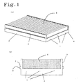
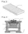
- This integrally molded type filter unit can be produced to be in a form shown in FIG. 1A and FIG. 1B by assembling and setting a filter part 5, which is made ready in another process and formed in a sheet-like shape or processed in pleated state as shown in FIG. 2 using a nonwoven fabric containing an adsorbent such as activated carbon, in dies for a filter holding frame as illustrated in FIG. 3 and FIG. 4 and injection-molding a thermoplastic resin. Simultaneously with that, the filter part and the holding frame are joined to each other to give filter unit in the form shown in FIG. 1A and FIG. 1B.
- the method for manufacturing the filter unit according to the present invention is an integrally molding method for sticking a filter part made of a filtration material 5 previously mad ready in another process to a filter holding frame simultaneously with molding of the filter holding frame.
- FIG. 1 The filter unit whole body relevant to an embodiment of the present invention is shown in FIG. 1 and the filter part is shown in FIG. 2 and the dies to be employed for the integrally molding process are shown in FIG. 3 and FIG. 4.
- the reference number 3 denotes the side face of the filter holding frame in the filtration material arrangement direction
- the reference number 4 denotes the side face of the filter holding frame in the filtration material width direction.
- the groove for which the reference number 14 is assigned in FIG. 4 forms a rib (the reference number 2 in FIG. 1 is assigned to: the reference number 6 in the same FIG. 1B shows the rib width and the reference number 7 shows the rib thickness) in the outside of the side face (in the filtration material arrangement direction) of the inj ection-moldedfilter frame part.
- the reference number 16 in the FIG. 4 corresponds to a gate (the reference number 1 in FIG. 1 is assigned to) positioned in the face of the filter frame part in the filtration material width direction.
- the reference number 10 shown in FIG. 3 and FIG. 5 denotes the serration part of the lower die in which the sheet for the filter 5 is set in pleated state.
- the filter holding frame is composed of two upper and lower separate dies 11, 12: an upper die in the fixed side and a lower die in the movable side. That is, the filtration material 5 is put between the two dies 11, 12 and the filter holding frame is produced from a resin by injection-molding in the cavity formed between the upper and the lower dies and simultaneously the holding frame and the filtration material 5 are joined together.
- a melted resin flows in resin fluidizing routes 8, 13 shown in FIG. 3 and is spread to the dies from the gates 1 in the side face in the width direction of the pleats of the filter holding frame.
- the resin introduction is carried out by introducing the resin from side faces in both sides in the width direction of the pleated filtration material of the filter holding frame and joined in the center of the side faces in the filtration material arrangement direction of the filter holding frame.
- the melted resin can flow quickly and is smoothly spread to the gap all over the dies, so that the above described short does not take place.
- the flow-in of the melted resin to the dies is completed within 15 to 20 seconds. After that, it takes 30 to 35 second to cool the inside of the dies. After the cooling, the dies 11, 12 are separated up and down to obtain an aiming filter unit.
- the reference number 9 in FIG. 3 shows the joined figure of the upper and the lower dies
- the clearance A of an escape part is controlled to be 80 to 115% to the thickness of the foregoing filtration material
- the clearance B in the grip part 17 is controlled to be 25 to 45%
- the distance C of the grip part 17 is controlled to be 0.5 to 5 mm, preferably 1 to 3 mm. Melting adhesion can perfectly be carried out by pressure joining the cavity and the core without causing bleeding of the melted resin for the holding frame to the filtration material.
- the filtration material and the holding frame can be joined to each other without causing separation of the activated carbon in the filtration material and damages on the filtration material and the activated carbon-containing filtration material and the holding frame can directly be joined to each other. Consequently, the effective surface area of the activated carbon-containing filtration material is widened and that contributes to remarkable improvement of the filter capability.
- the gap between the dies for the holding frame part can be narrowed, that is, the thickness of the produced filter holding frame can be made thin.
- the hardened resin can reinforce the side faces (filtration material arrangement direction) of the filter holding frame to significantly improve the strength of the produced filter.
- the filter unit In the case of manufacturing a filter unit using the dies of the embodiment of the present invention, separate production one by one is possible, however since the occurrence of defective products owing to the short is almost zero, the method is suitable for continuous production and possible to improve the productivity. Further, since the filter unit has excellent installation easiness, the filter unit is suitable to be used for vehicles, however the use of the filter unit is not at all restricted to such a purpose and the filter unit is suitable for a wide range of use purposes for a gas treatment apparatus.
- the thickness was measured by a thickness meter of a measurement terminal of 25 mm ⁇ at measurement load of 7 gf/cm 2 .
- the ventilation resistance of filtration materials was measured at wind velocity of 48 cm/s.
- toluene removal efficiency (downstream side concentration/upstream side concentration) ⁇ 100 [%].
- the effective surface area of filtration materials of filter parts in filter units was measured by a method according to JIS L 1096 8.18.
- the rein amount of polypropylene used for holding frames was measured.
- the ventilation resistance of filter units was measured at flow rate of a wind of 600 m 3 /hr.
- an activated carbon-containing sheet having 1.1 mm filtration material thickness, 22 to 26 kg-cm toughness in the width direction, 45 to 50 % modulus of compressive elasticity in the thickness direction, 50% or higher toluene removal efficiency of the filtration material, and 90 Pa or lower filtration material pressure loss was pleated in 39 mm height of pleats and 9 mm intervals of pleats and then cut in 105.5 filtration material width.
- the filtration material 5 was inserted into the insert part, that is, the filtration material insertion part 15, of the dies previously made ready and shown in FIG. 4.
- the clearance A of the escape part in the dies was controlled to be 105% to the thickness of the filtration material, that is, 1.16 mm; the clearance B in the grip part to be 40%, that is, 0.44 mm; and the distance C of the grip part to be 1.5 mm.
- the filtration material 5 was inserted into the dies and polypropylene resin (produced by C & CTECH Co.) melted at 215°C was poured to the gap between dies as shown in FIG. 4 by an injection-molding apparatus from gates at 6 points through resin fluidizing routes 8 of the dies shown in FIG. 3 by applying pressure of 50 kgf/cm 2 . At that time, the injection time to the dies was 15 seconds and cooling after the injection was carried out for 35 seconds.
- the filter unit had the filter unit outer size of 106 mm ⁇ 222 mm ⁇ 40 mm, the filter part size of 103 mm ⁇ 216 mm ⁇ 39 mm, pleat intervals of 9 mm and comprised a filter holding frame having the holding frame thickness of 1.5 mm, the rib thickness of 0.5 mm, and the rib width 6 mm.
- the properties of the filter unit as a filter were measured.
- the same filter part as that of Example 1 was used.
- the formation method of the filter unit was also same as in Example 1 except that the dies were so constituted as to control the clearance A of the escape part be 103% to the thickness of the filtration material, that is, 1.13 mm; the clearance B in the grip part to be 35%, that is, 0.39 mm; and the distance C of the grip part to be 3 mm, that the thickness of the flowing-in part of the dies was changed, and that the thickness of the holding frame was changed to be 3 mm.
- Example 2 The same filter part as that of Example 1 was used.
- the formation method of the filter unit was also same as in Example 1 except that the dies were so constituted as to control the clearance A of the escape part be 100% to the thickness of the filtration material, that is, 1.1 mm and no grid was formed.
- Example 2 The same filter part as that of Example 1 was used.
- the formation method of the filter unit was also same as in Example 1 except that the dies were so constituted as to control the clearance A of the escape part be 70% to the thickness of the filtration material, that is, 0.77 mm; the clearance B in the grip part to be 40%, that is, 0.44 mm; and the distance C of the grip part to be 1.5 mm.
- Example 2 The same filter part as that of Example 1 was used.
- the formation method of the filter unit was also same as in Example 1 except that the dies were so constituted as to control the clearance A of the escape part be 130% to the thickness of the filtration material, that is, 1.43 mm; the clearance B in the grip part to be 40%, that is, 0.44 mm; and the distance C of the grip part to be 1.5 mm.
- Example 2 The same filter part as that of Example 1 was used.
- the formation method of the filter unit was also same as in Example 1 except that the dies were so constituted as to control the clearance A of the escape part be 105% to the thickness of the filtration material, that is, 1.16 mm; the clearance B in the grip part to be 60%, that is, 0.66 mm; and the distance C of the grip part to be 1.5 mm.
- Example 2 The same filter part as that of Example 1 was used.
- the formation method of the filter unit was also same as in Example 1 except that the dies were so constituted as to control the clearance A of the escape part be 105% to the thickness of the filtration material, that is, 1.16 mm; the clearance B in the grip part to be 40%, that is, 0.44 mm; and the distance C of the grip part to be 6 mm.
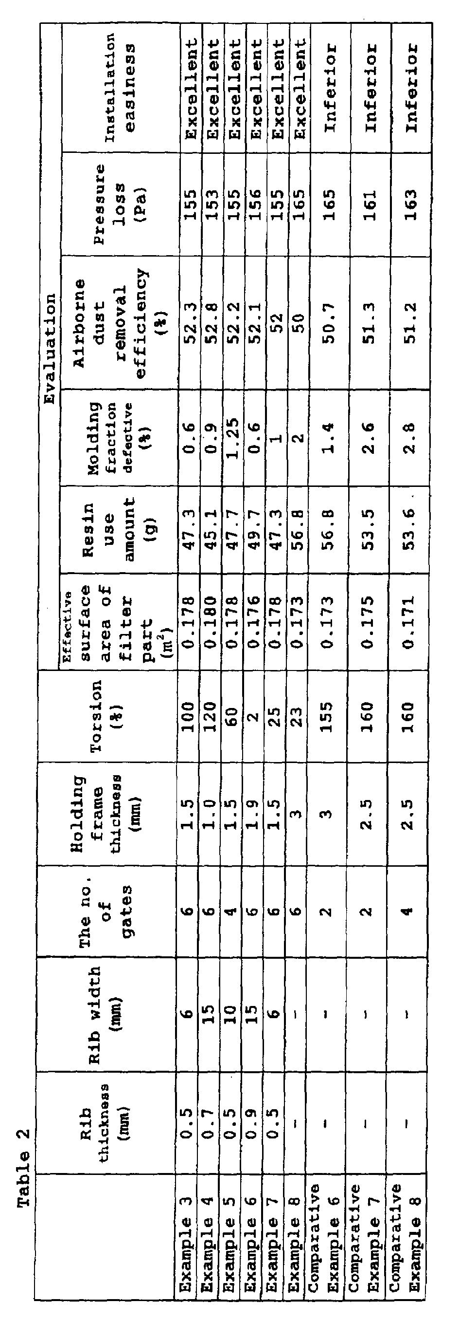
- Tests were carried out for airborne dust removal efficiency of the following filtration materials and filter units instead of the toluene removal efficiency of filtration materials, the torsion, and the installation easiness.
- the dust removal efficiency by one pass was measured using airborne dust of 0.3 ⁇ m.
- the concentration of the airborne dust of 0.3 ⁇ m in the upstream side and in the downstream side at wind velocity of 23 cm/s was measured using a powder dust measuring apparatus (trade name: RION PARTICLE COUNTER KC-01C).
- the airborne dust removal efficiency of a filtration material was calculated from the results.
- the dust removal efficiency by one pass was measured using airborne dust of 0.3 ⁇ m.
- the concentration of the airborne dust of 0.3 ⁇ m in the upstream side and in the downstream side at flow rate of 300 m 3 /hr of air was measured using a powder dust measuring apparatus (trade name: RION PARTICLE COUNTER KC-01C).
- the airborne dust removal efficiency of a filter unit was calculated from the results.
- the torsion was calculated by measuring the distance in which a holding frame was moved owing to the strain when force was applied to the filtration material face in one end of the holding frame in the vertical direction while a side face in the opposed other end of the holding frame being fixed in the filtration material width direction, dividing the distance with the width of the side face of the holding frame and multiplying the obtained value by 100.
- a sheet having 1.1 mm filtration material thickness, 22 to 26 kg-cm toughness in the width direction, 45 to 50 % modulus of compressive elasticity in the thickness direction, 40% or higher removal efficiency of airborne dust of 0.3 ⁇ m particle size, and 90 Pa or lower pressure loss was pleated in 39 mm height of pleats and 9 mm intervals of pleats and then cut in 105.5 filtration material width.
- the filtration material 5 was inserted into the insert part, that is, the filtration material insertion part 15, of the dies previously made ready and shown in FIG. 4.
- polypropylene resin produced by C & CTECH Co.
- melted at 215°C was poured to the gap between dies as shown in FIG. 4 by an injection-molding apparatus from gates at 6 points through resin fluidizing routes 8 of the dies shown in FIG. 3 by applying pressure of 50 kgf/cm 2 .
- the injection time to the dies was 15 seconds and cooling after the injection was carried out for 35 seconds. After that, the dies were separated up and down to take out a filter unit.
- a filter unit was obtained and it had the filter unit outer size of 106 mm ⁇ 222 mm ⁇ 40 mm, the filter part size of 103 mm ⁇ 216 mm ⁇ 39 mm, pleat intervals of 9 mm and comprised a filter holding frame having the holding frame thickness of 1.5 mm, the rib thickness of 0.5 mm, and the rib width 6 mm.
- the properties of the filter unit as a filter were measured and the installation easiness at the time of installation in a stand of a gas treatment apparatus was judged.
- Example 3 The same filter part as that of Example 3 was used.
- the formation method of the filter unit was also same as in Example 3 except that the thickness of flowing-in part of dies for a resin was changed. Consequently, the thickness of the filter holding frame was 1.0 mm, the rib thickness was 0.7 mm, and the rib width was 15 mm.
- Example 4 The same procedure as Example 4 was employed except that the number of gates was decreased to 4 points to obtain a filter unit having the thickness of the filter holding frame of 1.5 mm, the rib thickness of 0.5 mm, and the rib width of 10 mm.
- Example 1 the same procedure as Example 4.
- Example 3 The same conditions as those in Example 3 were employed to obtain a filter unit having the thickness of the filter holding frame of 1.9 mm, the rib thickness of 0.9 mm, and the rib width of 15 mm. Hereinafter, the same as Example 1.
- Example 3 The same conditions as those in Example 3 were employed except that an elastomer resin [produced by Mitsui Chemicals Inc., MILASTOMER (trade name)] was used as a molding resin instead of the polypropylene resin.
- an elastomer resin produced by Mitsui Chemicals Inc., MILASTOMER (trade name)
- MILASTOMER trade name
- Example 7 The same conditions as those in Example 7 were employed except that no rib was formed.
- Example 3 The same conditions as those in Example 3 were employed for the filter part and filter unit formation method except that the number of gates was decreased to 2 points and no rib was formed.
Landscapes
- Chemical & Material Sciences (AREA)
- Chemical Kinetics & Catalysis (AREA)
- Engineering & Computer Science (AREA)
- Manufacturing & Machinery (AREA)
- Mechanical Engineering (AREA)
- Filtering Of Dispersed Particles In Gases (AREA)
- Filtering Materials (AREA)
- Water Treatment By Sorption (AREA)
Abstract
Description

Claims (15)
- A filter unit comprising a filter part made of an adsorbent-bearing filtration material (5) and characterized in that said filter part is integrally molded with a filter holding frame made of a thermoplastic resin and that said adsorbent of said filter part is packed to the position contacting the filter holding frame.
- The filter unit according to claim 1, characterized in that said filter holding frame has 1% or higher torsion defined as the following equation:
- A filter unit comprising a filter part made of a filtration material (5) and characterized in that said filter part is integrally molded with a filter holding frame made of a thermoplastic resin and that said filter holding frame has 1% or higher torsion defined as the following equation:
- The filter unit according to any one of claims 1 to 3, characterized in that said filter holding frame has ribs (2) in the side faces in the filtration material arrangement direction.
- The filter unit according to claim 4, characterized in that the width (6) of said ribs is 10 to 90% to the width of each side face of said filter holding frame in the filtration material arrangement direction and the thickness (7) of said ribs is 10 to 70% to the thickness of each side face in the filtration material arrangement direction.
- The filter unit according to any one of claims 1 to 5, characterized in that said filter holding frame has 3 or more gates (1) in the side faces in the filtration material arrangement direction.
- The filter unit according to any one of claims 1 to 6, characterized in that said thermoplastic resin is an olefin type thermoplastic resin elastomer.
- The filter unit according to any one of claims 1 to 7, characterized in that the thickness of said filter holding frame is 2 mm or thinner and said torsion is 25 to 150%.
- A method for manufacturing a filter unit comprising a process of installing a filter part made of an adsorbent-bearing a filtration material (5) in the inside of dies (11,12) and a process of forming a filter holding frame integrally with said filter part by pouring a thermoplastic resin to the inside of said dies in which said filter part is installed and characterized in that the clearance A of an escape part in said dies (11, 12) is controlled to be 80 to 115% to the thickness of said filtration material, the clearance B in a grip part (17) is controlled to be 25 to 45% to the thickness of said filtration material, and the distance C of said grip part is controlled to be 0.5 to 5 mm.
- The method for manufacturing a filter unit according to claim 9, characterized in that the process of integrally forming said filter part and said filter holding frame is carried out by simultaneous joining by an injection molding method.
- The method for manufacturing a filter unit according to claim 9 or claim 10, characterized in that ribs (2) are formed in the side faces of said filter holding frame in the filtration material arrangement direction.
- The method for manufacturing a filter unit according to any one of claims 9 to 11, characterized in that the width (6) of said ribs (2) is controlled to be 10 to 90% to the width of each side face of said filter holding frame in the filtration material arrangement direction and the thickness (7) of said ribs is controlled to be 10 to 70% to the thickness of each side face in the filtration material arrangement direction.
- The method for manufacturing a filter unit according to any one of claims 9 to 12, characterized in that 3 or more gates (1) are formed in the side faces of said filter holding frame in the filtration material width direction.
- The method for manufacturing a filter unit according to any one of claims 9 to 13, characterized in that the thickness of said filter holding frame is controlled to be 2 mm or thinner.
- The method for manufacturing a filter unit according to any one of claims 9 to 14, characterized in that said thermoplastic resin is an olefin type thermoplastic elastomer.
Applications Claiming Priority (2)
| Application Number | Priority Date | Filing Date | Title |
|---|---|---|---|
| JP2000056616A JP2001239121A (en) | 2000-03-02 | 2000-03-02 | Filter unit and method of manufacturing the same |
| JP2000056616 | 2000-03-02 |
Publications (3)
| Publication Number | Publication Date |
|---|---|
| EP1129760A2 true EP1129760A2 (en) | 2001-09-05 |
| EP1129760A3 EP1129760A3 (en) | 2001-11-28 |
| EP1129760B1 EP1129760B1 (en) | 2007-07-25 |
Family
ID=18577526
Family Applications (1)
| Application Number | Title | Priority Date | Filing Date |
|---|---|---|---|
| EP01104505A Expired - Lifetime EP1129760B1 (en) | 2000-03-02 | 2001-03-01 | Integrally molded filter unit |
Country Status (4)
| Country | Link |
|---|---|
| US (1) | US6416570B2 (en) |
| EP (1) | EP1129760B1 (en) |
| JP (1) | JP2001239121A (en) |
| DE (1) | DE60129493D1 (en) |
Cited By (21)
| Publication number | Priority date | Publication date | Assignee | Title |
|---|---|---|---|---|
| DE10204162A1 (en) * | 2002-02-01 | 2003-08-14 | Freudenberg Carl Kg | Filter insert for a vehicle interior compartment air filter has a zigzag folded filter element whose edges are embedded in extensions of an injection molded frame |
| EP1464372A1 (en) * | 2003-04-02 | 2004-10-06 | Dana Corporation | Filter elements having injection molded thermoplastic seals and methods of making same |
| FR2875713A1 (en) * | 2004-09-29 | 2006-03-31 | Valeo Materiaux De Friction Sa | AIR FILTRATION DEVICE, METHOD AND DEVICE FOR MANUFACTURING AND INSTALLING AIR CIRCULATION IN A MOTOR VEHICLE |
| FR2880286A1 (en) * | 2004-12-30 | 2006-07-07 | Valeo Materiaux De Friction Sa | Air filter especially for vehicle air conditioning system has stiffening element joined to supple channeling wall by thermal welding without added material |
| US7300486B1 (en) | 2003-04-02 | 2007-11-27 | Wix Filtration Corp Llc | Filter elements having injection molded thermoplastic seals and methods of making same |
| EP1870150A1 (en) * | 2006-06-23 | 2007-12-26 | Unilever N.V. | Filter and process to prepare the same |
| EP2221100A4 (en) * | 2007-11-16 | 2011-07-06 | Nitto Denko Corp | Filter unit, filter unit panel using the same, and method of manufacturing filter unit |
| WO2013149532A1 (en) * | 2012-04-05 | 2013-10-10 | 福建华昆特种汽车配件有限公司 | Use of tpe in air filter fixing frame |
| EP1606035B1 (en) * | 2003-03-27 | 2016-07-20 | Valeo Matériaux de Friction | Method for making an air filter device, air filter device and airflow installation in a motor vehicle |
| US9795911B2 (en) | 2004-08-06 | 2017-10-24 | Donaldson Company, Inc. | Air filter arrangement; assembly; and, methods |
| US10434454B2 (en) | 2011-06-30 | 2019-10-08 | Donaldson Company, Inc. | Filter cartridge |
| US10610816B2 (en) | 2013-06-28 | 2020-04-07 | Donaldson Company, Inc. | Filter cartridges; air cleaner assemblies; housings; features; components; and, methods |
| US11020698B2 (en) | 2015-12-11 | 2021-06-01 | Cummins Filtration Ip, Inc. | Filter with variable cross-section axial seal |
| US11141687B2 (en) | 2016-05-02 | 2021-10-12 | Cummins Filtration Ip, Inc. | Filter with interlocking housing interface |
| US11167234B2 (en) | 2016-03-18 | 2021-11-09 | Cummins Filtration Ip, Inc. | Interlocked stable filter assembly |
| US11198082B2 (en) | 2017-08-31 | 2021-12-14 | Donaldson Company, Inc. | Filter cartridges; air cleaner assemblies; housings; features; components; and methods |
| US11235275B2 (en) | 2017-03-16 | 2022-02-01 | Cummins Filtration Ip, Inc. | Filtration sealing system |
| US11298640B2 (en) | 2017-01-25 | 2022-04-12 | Cummins Filtration Ip, Inc. | Expandable threaded adaptor for threadless shell |
| US11724220B2 (en) | 2017-02-21 | 2023-08-15 | Cummins Filtration Ip, Inc. | Undulated interlocking housing-endplate interface geometry |
| US12263428B2 (en) | 2018-07-23 | 2025-04-01 | Cummins Filtration Sarl | Radial seal for spin-on filter |
| US12576348B2 (en) | 2020-02-11 | 2026-03-17 | Atmus Filtration Inc. | Advanced fuel filtration system with interlocking cartridge seal design |
Families Citing this family (63)
| Publication number | Priority date | Publication date | Assignee | Title |
|---|---|---|---|---|
| DE19958344C2 (en) * | 1999-12-03 | 2001-12-20 | Freudenberg Carl Fa | Tool for manufacturing a filter cartridge with bellows and plastic frame |
| JP4670166B2 (en) * | 2001-03-21 | 2011-04-13 | トヨタ紡織株式会社 | Filter manufacturing method |
| JP2003071221A (en) * | 2001-09-05 | 2003-03-11 | Toyobo Co Ltd | Monolithic filter unit and method of manufacturing the same |
| JP2003071227A (en) * | 2001-09-05 | 2003-03-11 | Toyobo Co Ltd | Monolithic filter unit and method of manufacturing the same |
| US6736871B1 (en) * | 2002-12-09 | 2004-05-18 | Visteon Global Technologies, Inc. | Integrated filter screen and hydrocarbon adsorber |
| DE602004027472D1 (en) | 2003-03-18 | 2010-07-15 | Donaldson Co Inc | IMPROVED METHOD FOR WRAPPING Z-FILTER MEDIA |
| US20050025848A1 (en) * | 2003-07-30 | 2005-02-03 | Ruey-Fa Huang | Air filter shaping mold |
| US7070641B1 (en) * | 2003-12-03 | 2006-07-04 | Fleetguard, Inc. | Carbon media filter element |
| DE602005024558D1 (en) * | 2004-06-08 | 2010-12-16 | Donaldson Co Inc | Z-FILTER MEDIA PACKAGE ARRANGEMENT |
| WO2005123222A1 (en) | 2004-06-14 | 2005-12-29 | Donaldson Company, Inc. | Air filter arrangement; assembly; and, methods |
| ATE548102T1 (en) | 2005-01-13 | 2012-03-15 | Donaldson Co Inc | AIR FILTER ARRANGEMENT |
| EP1850943B1 (en) | 2005-01-13 | 2013-06-05 | Donaldson Company, Inc. | Air filter cartridge and air cleaner assembly |
| US20060254974A1 (en) * | 2005-02-02 | 2006-11-16 | Ibrahim Khalil | Filtration system with bypass valve flow control apparatus and method |
| US20060272304A1 (en) * | 2005-06-03 | 2006-12-07 | Louis Schupp John W | Air treatment apparatus and method of use thereof |
| EP1948347B1 (en) * | 2005-11-11 | 2010-07-21 | Carl Freudenberg KG | Laser welding method and filter element produced by it |
| USD549314S1 (en) * | 2006-03-10 | 2007-08-21 | Blue Air Ab | Air filter cartridge |
| US7625419B2 (en) | 2006-05-10 | 2009-12-01 | Donaldson Company, Inc. | Air filter arrangement; assembly; and, methods |
| US20070271887A1 (en) * | 2006-05-24 | 2007-11-29 | Mike Osborne | Nestable Filter and Frame |
| US7951219B2 (en) * | 2006-08-31 | 2011-05-31 | Honeywell International Inc. | Cast formed filter and method of making the same |
| US8728193B2 (en) | 2007-09-07 | 2014-05-20 | Donaldson Company, Inc. | Air filter assembly; components thereof and methods |
| GB0725015D0 (en) * | 2007-12-21 | 2008-01-30 | Madison Filter 981 Ltd | Filter element frames |
| DE102008027507A1 (en) * | 2008-06-10 | 2009-12-31 | Carl Freudenberg Kg | Filter element with a 2-K frame |
| US20100126128A1 (en) * | 2008-11-25 | 2010-05-27 | Scott Iii Richard J | Rigid cell filter assembly |
| US20110084017A1 (en) * | 2009-04-03 | 2011-04-14 | Delstar Technologies, Inc. | Reinforced, pleated filter structure |
| US8061530B2 (en) | 2009-04-09 | 2011-11-22 | Cummins Filtration Ip, Inc. | Filtration sealing system |
| DE102009056511A1 (en) * | 2009-12-02 | 2011-06-09 | Mann+Hummel Gmbh | Filter element and method of making a filter element |
| WO2011137367A1 (en) | 2010-04-30 | 2011-11-03 | Diversitech Corporation | Three-dimensional filter |
| GB2487987A (en) * | 2011-02-14 | 2012-08-15 | Fenchurch Environmental Group Ltd | Insert moulding |
| USD655804S1 (en) | 2011-06-27 | 2012-03-13 | Diversitech Corporation | Filter frame |
| USD655803S1 (en) | 2011-06-27 | 2012-03-13 | Diversitech Corporation | Filter frame |
| USD657858S1 (en) | 2011-06-27 | 2012-04-17 | Diversitech Corporation | Filter frame |
| USD655802S1 (en) | 2011-06-27 | 2012-03-13 | Diversitech Corporation | Filter frame |
| USD657859S1 (en) | 2011-06-27 | 2012-04-17 | Diversitech Corporation | Filter frame |
| USD708729S1 (en) | 2011-10-17 | 2014-07-08 | Diversitech Corporation | Filter frame |
| USD708311S1 (en) | 2011-10-17 | 2014-07-01 | Diversitech Corporation | Filter frame |
| USD685898S1 (en) | 2011-10-21 | 2013-07-09 | Diversitech Corporation | Filter frame |
| US10012118B2 (en) | 2013-01-31 | 2018-07-03 | Filtran Llc | Filter with dual pleat pack |
| US10130903B2 (en) | 2013-01-31 | 2018-11-20 | Filtran Llc | Filter with dual pleat pack |
| US20150108682A1 (en) * | 2013-10-23 | 2015-04-23 | Lincoln Global, Inc. | Method of making a filter seal |
| EP3194048B1 (en) | 2014-09-15 | 2020-07-08 | Donaldson Company, Inc. | Filter cartridge and air cleaner assembly |
| JP6687623B2 (en) | 2014-12-27 | 2020-04-22 | ドナルドソン カンパニー,インコーポレイティド | Air cleaner assembly and filter cartridge |
| USD820456S1 (en) | 2015-06-09 | 2018-06-12 | Lincoln Global, Inc. | Belt bracket of powered air purifying respirator |
| CN205037425U (en) * | 2015-07-02 | 2016-02-17 | 伊莱克斯瑞典公司 | Wall -mounted air conditioning |
| EP3448541B1 (en) * | 2016-04-28 | 2025-08-13 | Entegris, Inc. | Airborne molecular contamination filter cartridge system with combustible filter cartridge and reusable frame |
| WO2017202472A1 (en) | 2016-05-27 | 2017-11-30 | Electrolux Appliances Aktiebolag | Air conditioner with window connection |
| USD972698S1 (en) * | 2016-06-20 | 2022-12-13 | 3M Innovative Properties Company | Air filter |
| KR101850658B1 (en) * | 2017-11-20 | 2018-04-19 | 윤석상 | Dust collecting screen for thermal power plant and manufacturing method for the screen |
| WO2019114945A1 (en) | 2017-12-13 | 2019-06-20 | Electrolux Appliances Aktiebolag | Outdoor unit of an air conditioner |
| CN111433518A (en) | 2017-12-13 | 2020-07-17 | 伊莱克斯家用电器股份公司 | Window type air conditioner |
| WO2019114943A1 (en) | 2017-12-13 | 2019-06-20 | Electrolux Appliances Aktiebolag | Installation device for split air-conditioner |
| USD857306S1 (en) | 2018-03-07 | 2019-08-20 | Lincoln Global, Inc. | Top of helmet shell |
| USD860546S1 (en) | 2018-03-07 | 2019-09-17 | Lincoln Global, Inc. | Top shell for helmet |
| USD848077S1 (en) | 2018-03-07 | 2019-05-07 | Lincoln Global, Inc. | Cover lens frame |
| USD853044S1 (en) | 2018-03-07 | 2019-07-02 | Lincoln Global, Inc. | Inner shell of a helmet |
| USD851841S1 (en) | 2018-03-23 | 2019-06-18 | Lincoln Global, Inc. | Shield holder frame |
| US12123602B2 (en) | 2019-12-04 | 2024-10-22 | Electrolux Appliances Aktiebolag | Air-conditioner with fluid tank |
| US11168920B1 (en) | 2020-04-30 | 2021-11-09 | Midea Group Co., Ltd. | Window air conditioning unit anti-tip bracket assembly |
| KR20210157686A (en) * | 2020-06-22 | 2021-12-29 | 코웨이 주식회사 | Air filter and air clearner including the same |
| US11826682B2 (en) | 2021-08-24 | 2023-11-28 | Filtran Llc | Flow control elements and fluid apparatus including the same |
| US12152805B2 (en) | 2021-12-22 | 2024-11-26 | Electrolux Appliances Aktiebolag | Window air conditioning unit installation system |
| US11879647B2 (en) | 2021-12-22 | 2024-01-23 | Electrolux Appliances Aktiebolag | Portable air conditioning unit window installation system |
| US12313270B2 (en) | 2022-12-16 | 2025-05-27 | Midea Group Co., Ltd. | Window air conditioning unit retention bracket |
| US12241642B2 (en) | 2022-12-19 | 2025-03-04 | Midea Group Co., Ltd. | Apparatus and method of retention of a window air conditioning unit within a window assembly |
Family Cites Families (17)
| Publication number | Priority date | Publication date | Assignee | Title |
|---|---|---|---|---|
| DE370222C (en) | 1921-08-16 | 1923-02-28 | Hoechst Ag | Process for the preparation of tetraoxyquinone |
| JPS5730526A (en) * | 1980-07-29 | 1982-02-18 | Brother Ind Ltd | Filtering device and its manufacture |
| AU540096B2 (en) * | 1982-08-04 | 1984-11-01 | Nippondenso Co. Ltd. | Filter device and manufacturing method |
| JPS6041517A (en) * | 1983-08-13 | 1985-03-05 | Toyo Roki Seizo Kk | Manufacture of air cleaner element |
| US4701197A (en) * | 1986-10-07 | 1987-10-20 | Allied Corp. | Molded panel filter |
| JPS63287521A (en) * | 1987-05-19 | 1988-11-24 | Shuji Harada | Dust net for air cleaner and production thereof |
| US5043000A (en) * | 1987-09-18 | 1991-08-27 | Toyo Roki Seizo K.K. | Air cleaner element and method of manufacturing the same |
| DE3839352A1 (en) * | 1988-11-22 | 1990-05-23 | Sueddeutsche Kuehler Behr | AIR CONDITIONER FILTER FOR A MOTOR VEHICLE |
| DE4040104A1 (en) | 1990-12-16 | 1992-06-17 | Behr Gmbh & Co | FILTERS FOR AN AIR CONDITIONING OR HEATING SYSTEM FOR A MOTOR VEHICLE |
| US5352274A (en) * | 1993-05-10 | 1994-10-04 | Blakley Richard L | Air filter and method |
| US5679122A (en) * | 1993-08-14 | 1997-10-21 | Minnesota Mining & Manufacturing Company | Filter for the filtration of a fluid flow |
| US5891207A (en) | 1994-01-06 | 1999-04-06 | Hks Co., Ltd. | Engine intake-air filter apparatus |
| DE4432339C2 (en) * | 1994-09-10 | 1998-10-08 | Sandler Helmut Helsa Werke | Filter device |
| US5667545A (en) * | 1995-07-03 | 1997-09-16 | Toyoda Boshoku Corporation | Filter element for air cleaner and method of manufacturing the same |
| JP3761585B2 (en) * | 1996-10-24 | 2006-03-29 | スリーエム カンパニー | Filter device for fluid filtration |
| JP3662092B2 (en) | 1997-03-21 | 2005-06-22 | 東洋▲ろ▼機製造株式会社 | Filter element and manufacturing method thereof |
| JP3072279B2 (en) | 1997-12-26 | 2000-07-31 | 吉三郎 牧江 | Snow melting roof |
-
2000
- 2000-03-02 JP JP2000056616A patent/JP2001239121A/en active Pending
-
2001
- 2001-03-01 US US09/795,978 patent/US6416570B2/en not_active Expired - Fee Related
- 2001-03-01 DE DE60129493T patent/DE60129493D1/en not_active Expired - Lifetime
- 2001-03-01 EP EP01104505A patent/EP1129760B1/en not_active Expired - Lifetime
Cited By (39)
| Publication number | Priority date | Publication date | Assignee | Title |
|---|---|---|---|---|
| DE10204162B4 (en) * | 2002-02-01 | 2005-12-22 | Carl Freudenberg Kg | filter cartridge |
| DE10204162A1 (en) * | 2002-02-01 | 2003-08-14 | Freudenberg Carl Kg | Filter insert for a vehicle interior compartment air filter has a zigzag folded filter element whose edges are embedded in extensions of an injection molded frame |
| EP1606035B1 (en) * | 2003-03-27 | 2016-07-20 | Valeo Matériaux de Friction | Method for making an air filter device, air filter device and airflow installation in a motor vehicle |
| EP1464372A1 (en) * | 2003-04-02 | 2004-10-06 | Dana Corporation | Filter elements having injection molded thermoplastic seals and methods of making same |
| US7300486B1 (en) | 2003-04-02 | 2007-11-27 | Wix Filtration Corp Llc | Filter elements having injection molded thermoplastic seals and methods of making same |
| US7341613B2 (en) | 2003-04-02 | 2008-03-11 | Wix Filtration Corp Llc | Filter elements having injection molded thermoplastic seals and methods of making same |
| US9795911B2 (en) | 2004-08-06 | 2017-10-24 | Donaldson Company, Inc. | Air filter arrangement; assembly; and, methods |
| FR2875713A1 (en) * | 2004-09-29 | 2006-03-31 | Valeo Materiaux De Friction Sa | AIR FILTRATION DEVICE, METHOD AND DEVICE FOR MANUFACTURING AND INSTALLING AIR CIRCULATION IN A MOTOR VEHICLE |
| WO2006035189A1 (en) * | 2004-09-29 | 2006-04-06 | Valeo Materiaux De Friction | Air-filtering device, method and device for the production thereof and an air circulation system for a motor vehicle |
| FR2880286A1 (en) * | 2004-12-30 | 2006-07-07 | Valeo Materiaux De Friction Sa | Air filter especially for vehicle air conditioning system has stiffening element joined to supple channeling wall by thermal welding without added material |
| EP1681086A1 (en) * | 2004-12-30 | 2006-07-19 | Valeo Matériaux de Friction | Air filtration device with flexible walls, in particular for motor vehicle |
| EP1870150A1 (en) * | 2006-06-23 | 2007-12-26 | Unilever N.V. | Filter and process to prepare the same |
| CN101472659B (en) * | 2006-06-23 | 2012-01-11 | 荷兰联合利华有限公司 | Filter and process to prepare the same |
| WO2007147716A1 (en) * | 2006-06-23 | 2007-12-27 | Unilever N.V. | Filter and process to prepare the same |
| EP2221100A4 (en) * | 2007-11-16 | 2011-07-06 | Nitto Denko Corp | Filter unit, filter unit panel using the same, and method of manufacturing filter unit |
| US10434454B2 (en) | 2011-06-30 | 2019-10-08 | Donaldson Company, Inc. | Filter cartridge |
| WO2013149532A1 (en) * | 2012-04-05 | 2013-10-10 | 福建华昆特种汽车配件有限公司 | Use of tpe in air filter fixing frame |
| US11752460B2 (en) | 2013-06-28 | 2023-09-12 | Donaldson Company, Inc. | Filter cartridges; air cleaner assemblies; housings; features; components; and, methods |
| US11298643B2 (en) | 2013-06-28 | 2022-04-12 | Donaldson Company, Inc. | Filter cartridges; air cleaner assemblies; housings; features; components; and, methods |
| US12186694B2 (en) | 2013-06-28 | 2025-01-07 | Donaldson Company, Inc. | Filter cartridges; air cleaner assemblies; housings; features; components; and, methods |
| US12115484B2 (en) | 2013-06-28 | 2024-10-15 | Donaldson Company, Inc. | Filter cartridges; air cleaner assemblies; housings; features; components; and, methods |
| US10610816B2 (en) | 2013-06-28 | 2020-04-07 | Donaldson Company, Inc. | Filter cartridges; air cleaner assemblies; housings; features; components; and, methods |
| USRE50860E1 (en) | 2015-12-11 | 2026-04-14 | Atmus Filtration IP Inc. | Filter with variable cross-section axial seal |
| US11020698B2 (en) | 2015-12-11 | 2021-06-01 | Cummins Filtration Ip, Inc. | Filter with variable cross-section axial seal |
| US11813559B2 (en) | 2016-03-18 | 2023-11-14 | Cummins Filtration Ip, Inc. | Interlocked stable filter assembly |
| US12551830B2 (en) | 2016-03-18 | 2026-02-17 | Atmus Filtration IP Inc. | Interlocked stable filter assembly |
| US11167234B2 (en) | 2016-03-18 | 2021-11-09 | Cummins Filtration Ip, Inc. | Interlocked stable filter assembly |
| US11660560B2 (en) | 2016-05-02 | 2023-05-30 | Cummins Filtration Ip, Inc. | Filter with interlocking housing interface |
| US11141687B2 (en) | 2016-05-02 | 2021-10-12 | Cummins Filtration Ip, Inc. | Filter with interlocking housing interface |
| US11298640B2 (en) | 2017-01-25 | 2022-04-12 | Cummins Filtration Ip, Inc. | Expandable threaded adaptor for threadless shell |
| US11724220B2 (en) | 2017-02-21 | 2023-08-15 | Cummins Filtration Ip, Inc. | Undulated interlocking housing-endplate interface geometry |
| US12330099B2 (en) | 2017-02-21 | 2025-06-17 | Cummins Filtration Ip, Inc. | Undulated interlocking housing-endplate interface geometry |
| US11235275B2 (en) | 2017-03-16 | 2022-02-01 | Cummins Filtration Ip, Inc. | Filtration sealing system |
| US11801466B2 (en) | 2017-08-31 | 2023-10-31 | Donaldson Company, Inc. | Filter cartridges; air cleaner assemblies; housings; features; components; and, methods |
| US12357934B2 (en) | 2017-08-31 | 2025-07-15 | Donaldson Company, Inc. | Filter cartridges; air cleaner assemblies; housings; features; components; and, methods |
| US12036499B2 (en) | 2017-08-31 | 2024-07-16 | Donaldson Company, Inc | Filter cartridges; air cleaner assemblies; housings; features; components; and, methods |
| US11198082B2 (en) | 2017-08-31 | 2021-12-14 | Donaldson Company, Inc. | Filter cartridges; air cleaner assemblies; housings; features; components; and methods |
| US12263428B2 (en) | 2018-07-23 | 2025-04-01 | Cummins Filtration Sarl | Radial seal for spin-on filter |
| US12576348B2 (en) | 2020-02-11 | 2026-03-17 | Atmus Filtration Inc. | Advanced fuel filtration system with interlocking cartridge seal design |
Also Published As
| Publication number | Publication date |
|---|---|
| DE60129493D1 (en) | 2007-09-06 |
| EP1129760B1 (en) | 2007-07-25 |
| EP1129760A3 (en) | 2001-11-28 |
| US6416570B2 (en) | 2002-07-09 |
| JP2001239121A (en) | 2001-09-04 |
| US20010032545A1 (en) | 2001-10-25 |
Similar Documents
| Publication | Publication Date | Title |
|---|---|---|
| US6416570B2 (en) | Integrally molded type filter unit and manufacture of the same | |
| RU2401143C1 (en) | Moulded single-component one-layer breather | |
| US7947142B2 (en) | Pleated filter with monolayer monocomponent meltspun media | |
| EP2054136B1 (en) | Pleated filter with bimodal monolayer monocomponent media | |
| EP2049720B1 (en) | Method for making shaped filtration articles | |
| EP2247361B1 (en) | Filter element frames | |
| US8696783B2 (en) | Filter unit | |
| AU636955B2 (en) | Filter cartridge | |
| KR20090038440A (en) | Single-Component Single Melt Blown Web and Melt Blowing Devices | |
| US12017175B2 (en) | Pleated air filter with bridging filaments and continuous-contact filaments | |
| EP3041981A1 (en) | Melt-spinning process, melt-spun nonwoven fibrous webs and related filtration media | |
| US6732868B2 (en) | Production method and apparatus for filter, forming die for filter, forming assembly for forming filter, and filter | |
| JPS5825488B2 (en) | Manufacturing method of air filter for air conditioner | |
| JP2003071227A (en) | Monolithic filter unit and method of manufacturing the same | |
| EP1464372B1 (en) | Filter elements having injection molded thermoplastic seals and methods of making same | |
| JP2003071221A (en) | Monolithic filter unit and method of manufacturing the same | |
| JP4022663B2 (en) | Monolithic filter unit and manufacturing method thereof | |
| JP2002219320A (en) | Filter unit and method of manufacturing the same | |
| JP2003071217A (en) | Monolithic filter unit and method of manufacturing the same | |
| WO2005118112A1 (en) | Manufacturing method of an air-cleaning filter and air cleaning filter manufactured by the method | |
| JP2009262115A (en) | Air filter unit | |
| JP4156096B2 (en) | air filter | |
| JP4154584B2 (en) | Filter unit | |
| EP1240933A2 (en) | Production method and apparatus for filter, forming die for filter, forming assembly for forming filter, and filter | |
| JP3775267B2 (en) | Air cleaner element pleat contact prevention member and air cleaner element |
Legal Events
| Date | Code | Title | Description |
|---|---|---|---|
| PUAI | Public reference made under article 153(3) epc to a published international application that has entered the european phase |
Free format text: ORIGINAL CODE: 0009012 |
|
| AK | Designated contracting states |
Kind code of ref document: A2 Designated state(s): AT BE CH CY DE DK ES FI FR GB GR IE IT LI LU MC NL PT SE TR Kind code of ref document: A2 Designated state(s): DE FR GB |
|
| AX | Request for extension of the european patent |
Free format text: AL;LT;LV;MK;RO;SI |
|
| PUAL | Search report despatched |
Free format text: ORIGINAL CODE: 0009013 |
|
| AK | Designated contracting states |
Kind code of ref document: A3 Designated state(s): AT BE CH CY DE DK ES FI FR GB GR IE IT LI LU MC NL PT SE TR |
|
| AX | Request for extension of the european patent |
Free format text: AL;LT;LV;MK;RO;SI |
|
| 17P | Request for examination filed |
Effective date: 20020214 |
|
| AKX | Designation fees paid |
Free format text: DE FR GB |
|
| 17Q | First examination report despatched |
Effective date: 20030416 |
|
| GRAP | Despatch of communication of intention to grant a patent |
Free format text: ORIGINAL CODE: EPIDOSNIGR1 |
|
| RTI1 | Title (correction) |
Free format text: INTEGRALLY MOLDED FILTER UNIT |
|
| GRAS | Grant fee paid |
Free format text: ORIGINAL CODE: EPIDOSNIGR3 |
|
| RIN1 | Information on inventor provided before grant (corrected) |
Inventor name: MINEMURA, SHINICHI,C/O TOYO BOSEKI KABUSHIKI KAISH Inventor name: AKIYAMA, MITSUHIKO,C/O TOYO BOSEKI KABUSHIKI KAISH Inventor name: GOTO, SADAHITO,C/OTOYO BOSEKI KABUSHIKI KAISHA |
|
| GRAA | (expected) grant |
Free format text: ORIGINAL CODE: 0009210 |
|
| AK | Designated contracting states |
Kind code of ref document: B1 Designated state(s): DE FR GB |
|
| REG | Reference to a national code |
Ref country code: GB Ref legal event code: FG4D |
|
| REF | Corresponds to: |
Ref document number: 60129493 Country of ref document: DE Date of ref document: 20070906 Kind code of ref document: P |
|
| EN | Fr: translation not filed | ||
| PGFP | Annual fee paid to national office [announced via postgrant information from national office to epo] |
Ref country code: GB Payment date: 20080326 Year of fee payment: 8 |
|
| PLBE | No opposition filed within time limit |
Free format text: ORIGINAL CODE: 0009261 |
|
| STAA | Information on the status of an ep patent application or granted ep patent |
Free format text: STATUS: NO OPPOSITION FILED WITHIN TIME LIMIT |
|
| 26N | No opposition filed |
Effective date: 20080428 |
|
| PG25 | Lapsed in a contracting state [announced via postgrant information from national office to epo] |
Ref country code: FR Free format text: LAPSE BECAUSE OF FAILURE TO SUBMIT A TRANSLATION OF THE DESCRIPTION OR TO PAY THE FEE WITHIN THE PRESCRIBED TIME-LIMIT Effective date: 20080321 Ref country code: DE Free format text: LAPSE BECAUSE OF FAILURE TO SUBMIT A TRANSLATION OF THE DESCRIPTION OR TO PAY THE FEE WITHIN THE PRESCRIBED TIME-LIMIT Effective date: 20071026 |
|
| GBPC | Gb: european patent ceased through non-payment of renewal fee |
Effective date: 20090301 |
|
| PG25 | Lapsed in a contracting state [announced via postgrant information from national office to epo] |
Ref country code: GB Free format text: LAPSE BECAUSE OF NON-PAYMENT OF DUE FEES Effective date: 20090301 |