EP1129747A2 - Wedgeshaped element for a snowboardbinding - Google Patents
Wedgeshaped element for a snowboardbinding Download PDFInfo
- Publication number
- EP1129747A2 EP1129747A2 EP01420033A EP01420033A EP1129747A2 EP 1129747 A2 EP1129747 A2 EP 1129747A2 EP 01420033 A EP01420033 A EP 01420033A EP 01420033 A EP01420033 A EP 01420033A EP 1129747 A2 EP1129747 A2 EP 1129747A2
- Authority
- EP
- European Patent Office
- Prior art keywords
- element according
- plate
- plates
- inclination
- face
- Prior art date
- Legal status (The legal status is an assumption and is not a legal conclusion. Google has not performed a legal analysis and makes no representation as to the accuracy of the status listed.)
- Granted
Links
Images


Classifications
-
- A—HUMAN NECESSITIES
- A63—SPORTS; GAMES; AMUSEMENTS
- A63C—SKATES; SKIS; ROLLER SKATES; DESIGN OR LAYOUT OF COURTS, RINKS OR THE LIKE
- A63C10/00—Snowboard bindings
- A63C10/28—Snowboard bindings characterised by auxiliary devices or arrangements on the bindings
- A63C10/285—Pads as foot or binding supports, e.g. pads made of foam
-
- A—HUMAN NECESSITIES
- A63—SPORTS; GAMES; AMUSEMENTS
- A63C—SKATES; SKIS; ROLLER SKATES; DESIGN OR LAYOUT OF COURTS, RINKS OR THE LIKE
- A63C10/00—Snowboard bindings
- A63C10/16—Systems for adjusting the direction or position of the bindings
- A63C10/22—Systems for adjusting the direction or position of the bindings to fit the size of the shoe
-
- A—HUMAN NECESSITIES
- A63—SPORTS; GAMES; AMUSEMENTS
- A63C—SKATES; SKIS; ROLLER SKATES; DESIGN OR LAYOUT OF COURTS, RINKS OR THE LIKE
- A63C10/00—Snowboard bindings
- A63C10/16—Systems for adjusting the direction or position of the bindings
- A63C10/18—Systems for adjusting the direction or position of the bindings about a vertical rotation axis relative to the board
Definitions
- the invention relates to the field of sliding sports and more specifically that snowboarding or snowboarding. It relates more particularly to an element interface set up between the ends of the sole of the shoe and the binding or the surfboard, to fill the empty space between the sole and fixing or plank. Such interface elements are commonly called in the field of snowboarding by the English expression of "gas pedal”.
- the soft shoes have a sole that has a slight curvature such that the front and rear ends are slightly raised.
- One of the problems which the invention therefore proposes to solve is that of optimizing the contact between the wedge element and the sole of the shoe, to obtain the best possible transmission of forces, and whatever the shoe size and geometry.
- the invention therefore relates to a wedge element, intended to be secured to the front or rear end of the base of a surfboard binding, or directly to the upper face of the surfboard.
- This element has a top side intended to receive the supports from the front or rear end of the sole of the shoe.
- This element forming an inclined wedge comprises means for adjusting the angle. inclination, measured in a longitudinal plane, between the upper face of the wedge inclined and the upper face of the board, so as to be adaptable to several shoe geometries.
- the wedge element is characterized in that it also includes means capable of adjusting the longitudinal position of the face upper of the shim relative to the base of the binding.
- the characteristic element has a variable geometry which allows to adapt to different types and sizes of shoe sole in completely filling the volume between the surfboard and the below the sole.
- the angle of inclination is measured in a longitudinal plane which is perpendicular to the board and in the direction of orientation of the foot. So, when the user changes shoes and the sole of their new shoes is more raised at the front end or longer, it just change the inclination of the upper face of the wedge, and the position longitudinal of the latter so that its supports are just as effectively transmitted only with the old setting.
- the characteristic element may also include means capable of adjusting the angle of inclination, measured in a transverse plane, between the upper face of the wedge and the upper face of the board, so as to adapt to a position of the shoe inclined transversely. In this way, it is possible to optimize the position of the foot by a transverse inclination or "canting", while keeping good transmission of support at the front end of the shoe.
- the bottom plate can be an integral part of the base, of which it then constitutes a forward extension.
- the element is completely separate from the base and comes into place on this, or even on the board, at the front end of the base.
- the means capable of adjusting the inclination of the two plates comprise at least one screw cooperating with the two lower and upper plates.
- the lower plate has a thread receiving said screw, and the upper plate rests on the head of this screw so that the latter works in compression.
- the upper plate may have a suitable housing to receive the head of the screw, this housing then having an opening opening on the upper face of the upper plate to allow access to said head screw. This prevents the elements from protruding from the upper side of the wedge.
- the lower plate includes a thread receiving the screw, and it is the head of the screw which rests on the plate upper, so that the screwing of the screw brings the upper plate relative to the lower plate, return means being arranged to oppose this rimpedement.
- recall means are sufficiently stiff in compression to prevent the shoe from tipping over when efforts are exerted.
- the top plate may have a vertical flap oriented towards the bottom plate, and able to close the opening between the two plates to limit the introduction of snow.
- the space between the two plates can be filled with a compressible foam, so as to prevent the introduction of snow.
- the means capable of adjusting the inclination may consist of a moving part, the position of which is indexed relative to to the lower plate, the upper zone of which comes into contact with the lower face of the upper plate to determine the inclination relative to the plate lower.
- the articulation of the two lower plates and upper can be achieved by a connecting member capable of pressing the two plates against each other.
- the upper plate advantageously has a curve at the level of the area of cooperation with said connecting member so as to allow the inclination of the plates between them. In this way, the tilting movement of the top plate is allowed without generating mechanical stresses on this plate.
- the contact areas of the lower plates and upper have additional notches capable of ensuring blocking in longitudinal position of the two plates relative to each other. In this way, we eliminates any risk of the top plate shifting relative to the plate lower when it is under stress.
- the lower plate has a groove longitudinal in which part of the connecting member can move for ensure the longitudinal adjustment of the upper plate relative to the plate lower, the locking in position being provided by the aforementioned notched areas.
- the shim may include two adjusting screws located on either side of the median longitudinal plane of the element, so that ensure a distribution of the efforts limiting the risks of rupture of the troubles of mechanical.
- the wedge may comprise a transverse blade cooperating with the two screws, so as to ensure a better distribution over the entire width of the shim of the forces exerted by the upper plate.
- the wedge may include a seal interposed between the lower and upper plates.
- a layer of plastic material capable of camouflaging the screw heads may be provided.
- the invention relates to a wedge element intended to be installed at the front and / or rear of a surfboard binding, to fill the volume between the upper face of the board and the underside of the sole, when it is curved upwards.
- a wedge element intended to be installed at the front and / or rear of a surfboard binding, to fill the volume between the upper face of the board and the underside of the sole, when it is curved upwards.
- Figures 1a, 1b and 2 to 5 relate to a first embodiment in which the front part of the base (1) constitutes one of the plates of the element feature. More precisely this base has in its center an opening (2) intended to receive the adjustment disc in orientation of the binding. The part chamfered (3) serves in effect for indexing the disc, not shown.
- the front part (4) of the base rests directly on the upper face (5) of the board.
- This front part (4) of the base forms in its extreme part at the front a lower plate (6) above which a recess is produced (7) allowing the establishment of the upper plate (8), so that the upper face (9) of this upper plate (8) is in continuity with the face upper (10) of the central part of the base.
- the upper plate (8) is limited at the front and rear by edges in an arc.
- the rear edge (12) is substantially centered on the center (13) of the binding, while the front edge (11) conforms to the shape of the foot and is therefore slightly further forward on the inside (15) of the foot.
- the upper plate (8) is secured to the lower plate (6) or the front end of the base by a connecting member (20) consisting of a screw (21) and a shoulder nut (22).
- the head (23) of the screw fits into a housing (24) provided for this purpose on the top of the upper plate (8) and the nut shoulder (22) has its zone (25) of larger diameter which is housed the interior of a groove (26) provided for this purpose under the underside (27) of the base corresponding to the bottom plate of the hold.
- the lesser part diameter (28) of the shoulder nut (22) can move in an opening longitudinal (29) formed inside the lower plate (6). In this way, the connecting member (20) and therefore the upper plate (8) can move longitudinally between the two positions illustrated in Figures la and 1b.
- Maintaining the position of the upper plate (8) relative to the plate lower (6) is effected on the one hand, by the tightening of the connecting member (20), and on the other hand, by the cooperation of the two facing surfaces (30, 31) which are advantageously notched.
- the upper plate (8) has an orientation capacity with respect to the lower plate (6) for adapt to different shoe geometries. This orientation is obtained by pivoting of the upper plate (8) relative to the lower plate (6) or the end of the base, around the connecting member (20). This is why, the parts (33, 34) of the lower face of the upper plate (8) located in front and behind the connecting member (20) are not coplanar, but present at otherwise a slight inclination, so that when the top plate (8) pivots around the connecting member (20), the part (33) of the upper plate (8) located at the rear of the connecting member (20) can approach the face upper (37) of the lower plate (6) corresponding to the limit of the offset (7).
- the front part of the upper plate (8) has a flap (45) directed downwards, and which arrives when the upper plate (8) is in the lowest position almost in contact with the upper face (5) of the board.
- the front part of the upper plate (8) comprises, in its zones lateral, two threads (46) inside which a threaded rod can be screwed (47) whose lower zone includes a washer (48) intended to come into contact of the upper face (5) of the board.
- the upper part of the threaded rod (47) is accessible by the upper face (9) of the upper plate (8) at a housing (49) provided for this purpose, and which can advantageously be closed by a stud (50) made of plastic.
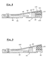
- FIG. 6 illustrates an alternative embodiment in which the lower plate (60) extends up to the vicinity of the flap (61) of the upper plate (62).
- the lower plate (60) has a zone (63) including a thread (64) into which a screw (65) enters, the head (66) of which passes through the plate upper (62) at the level of a housing (67) provided for this purpose.
- the head (66) of the screw (65) can be accompanied by a washer (68) intended to ensure good distribution of forces at the shoulder (69) of the housing (67).
- Means of recall such as an elastic foam stud (70), or springs (not shown) oppose the movement of the upper plate (62) downwards.
- the longitudinal adjustment of the shim is obtained by modifying the position of the lower plate (60) relative to the base (71).
- the base (71) and the rear part (72) of the lower plate (60) have an overlap zone.
- the rear part (72) of the upper plate has a longitudinal lumen (73) through which a screw (74) is screwed into the front end of the base.
- FIG. 7 An alternative embodiment illustrated in FIG. 7 operates according to a principle mechanically close.
- the screw (75) which penetrates into the thread (64) of the plate lower (6) has a spherical head (76) which comes into contact with a housing (78) of complementary shape formed on the underside (79) of the plate upper (80).
- This housing (78) opens out through a smaller opening (81) diameter to allow access to the screw head (76).
- the screw head (76) supports the forces transmitted by the upper plate (80), and therefore works in compression.
- the shim may include also a transverse plate, bearing on the two screws so as to distribute the forces exerted on them evenly.
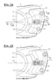
- FIGs 8 and 9 illustrate another embodiment of the invention, in which the bottom plate comprises an opening (92) inside which can pass a moving part (93). More specifically, the underside (94) of the bottom plate (90) comprises around the opening (92) a notched reserve (95) transversely.
- the opening (92) receives the moving part (93) composed of a base (96) and a stud (97) disposed substantially in its center. The upper side of the base (96) is notched in the same way as the reserve (95) opposite which she is. In this way, the moving part (93) can move longitudinally so that the stud (97) adopts an indexed position inside the opening (92).
- the upper part (98) of the stud comes into contact with the lower face of the plate upper and therefore receives the forces transmitted by this upper plate (100).
- the stud (97) bears on a different longitudinal level under the upper plate (100).
- the upper plate (100) is secured to the plate lower (90) by any mechanical attachment means.
- the inclination of the latter (100) varies according to the position of the moving part (93) as illustrated in FIGS. 8 and 9. Maintaining the moving part (93) in position is provided by the notching of the upper face of its base (96) and the reserve (95). This notching can even use forms engaging ensuring a slight click.
- the front ends (101, 102) of the lower plate (90) and upper plate (100) can be connected by a pad of compressible foam (103) providing support on the one hand and on the other hand, the tightness of the assembly.
- the moving part (93) may not have only one stud, located at the median level of the characteristic element, or still have several studs distributed over the width of the wedge, to ensure a better distribution of efforts.
Abstract
Description
L'invention concerne le domaine des sports de glisse et plus précisément celui du surf des neiges ou snowboard. Elle concerne plus particulièrement un élément interface mis en place entre les extrémités de la semelle de la chaussure et la fixation ou la planche de surf, pour combler l'espace vide existant entre la semelle et la fixation ou la planche. De tels éléments interfaces sont couramment appelés dans le domaine du snowboard par l'expression anglaise de "gaz pedal".The invention relates to the field of sliding sports and more specifically that snowboarding or snowboarding. It relates more particularly to an element interface set up between the ends of the sole of the shoe and the binding or the surfboard, to fill the empty space between the sole and fixing or plank. Such interface elements are commonly called in the field of snowboarding by the English expression of "gas pedal".
Comme on le sait, le surf se pratique soit avec des chaussures rigides ressemblant à des chaussures de ski alpin, soit avec des chaussures souples coopérant avec des fixations présentant des éléments d'origine, notamment une gouttière arrière destinée à procurer les appuis à la chaussure souple. L'invention se rattache plus précisément à cette famille de chaussures souples et de fixations adaptées. De telles chaussures sont en effet utilisées pour leur qualité de confort permettant à l'utilisateur de marcher sans gêne lorsqu'il a déchaussé sa planche.As we know, surfing is practiced either with rigid shoes resembles alpine ski boots, either with flexible boots cooperating with fasteners having original elements, in particular a rear gutter intended to provide support for the flexible shoe. The invention is relates more precisely to this family of flexible shoes and bindings adapted. Such shoes are indeed used for their quality of comfort allowing the user to walk without discomfort when he has taken off his board.
Or, pour permettre un bon déroulé du pied lors du mouvement de marche, les chaussures souples possèdent une semelle qui présente une légère courbure telle que les extrémités avant et arrière sont légèrement surélevées.However, to allow a good unrolling of the foot during the walking movement, the soft shoes have a sole that has a slight curvature such that the front and rear ends are slightly raised.
On conçoit donc au niveau des extrémités avant et/ou arrière de la chaussure, lorsque cette dernière est mise en place sur la fixation, il existe un certain volume inoccupé entre le dessous de la semelle de la chaussure et la face supérieure de l'embase de la fixation, ou bien encore la planche de glisse proprement dite en fonction de l'architecture de la fixation utilisée. Ce volume exempt de matière ne permet donc pas à l'utilisateur de transmettre les efforts au niveau des extrémités avant et/ou arrière du pied dont on sait par ailleurs, qu'il a constitué une des zones principales de transmission des appuis. We therefore design at the front and / or rear ends of the shoe, when the latter is placed on the binding, there is a certain volume unoccupied between the underside of the sole of the shoe and the upper face of the mounting base, or even the sliding board itself depending on the architecture of the fixing used. This material-free volume does not therefore does not allow the user to transmit the forces at the ends front and / or rear of the foot which we know moreover, that it constituted one of the zones main transmission of support.
Il est à noter que ce problème de la transmission efficace des appuis se pose de façon plus importante au niveau de l'extrémité avant de la chaussure, puisque les appuis au niveau de l'extrémité arrière de la chaussure sont assurés de façon prépondérante par la gouttière arrière de la fixation. Néanmoins, l'absence d'appui efficace au niveau de l'arrière du talon de la chaussure provoque des imprécisions au niveau des sensations reçues et donc de la conduite du surf.It should be noted that this problem of the efficient transmission of support arises more importantly at the front end of the shoe, since the supports at the rear end of the shoe are provided so predominant by the rear gutter of the binding. However, the lack of support effective at the back of the heel of the shoe causes inaccuracies in terms of the sensations received and therefore the conduct of the surf.
Pour résoudre ce problème, des solutions ont déjà été proposées.To solve this problem, solutions have already been proposed.
Dans le document US 5 503 900, on a décrit une fixation dont l'embase comporte des éléments additionnels situés aux extrémités avant et arrière. Ces éléments forment des cales inclinées dont la surface supérieure est destinée à venir au contact de la semelle de la chaussure au niveau avant et arrière. De la sorte, les efforts exercés à proximité de la pointe de la chaussure sont transmis en direction de l'embase via cet élément formant cale. Le jeu entre la semelle de la chaussure et la face supérieure de l'embase est supprimé, ce qui permet une transmission des efforts dès les premiers mouvements de la pointe du pied. L'inconvénient majeur de ces éléments formant cale est qu'ils ne peuvent pas s'adapter à différentes tailles de chaussures, et qu'il est donc nécessaire de les repositionner à chaque fois que l'utilisateur change de chaussures.In document US Pat. No. 5,503,900, a fixing has been described, the base of which has additional elements located at the front and rear ends. These elements form inclined wedges whose upper surface is intended to come in contact with the sole of the shoe at the front and rear level. In this way, the forces exerted near the tip of the shoe are transmitted towards of the base via this wedge element. The clearance between the sole of the shoe and the upper face of the base is removed, which allows transmission of efforts from the first movements of the toes. The major drawback of these wedge elements is that they cannot adapt to different sizes shoes, and it’s therefore necessary to reposition them each time the user changes shoes.
Par ailleurs, on a proposé dans le document WO 98/42419 de rendre les cales
réglables en positions longitudinale et transversale pour pouvoir s'adapter à
différentes configurations de semelle. Cependant, l'élément ayant une forme
déterminée, il ne peut pas correspondre à toutes les formes de semelle des
chaussures du marché. Une telle solution présente donc l'inconvénient majeur qu'en
fonction de différentes courbures de la semelle de la chaussure, il peut apparaítre
un certain jeu entre la semelle et l'élément formant cale. Ce jeu produit les effets
néfastes précités.Furthermore, it has been proposed in
On a proposé dans le document WO 00/30722 d'équiper l'embase d'une fixation de surf avec une cale articulée. Plus précisément, cette cale comporte deux pattes latérales qui autorisent le réglage de son inclinaison par rapport à l'embase. Cette solution permet de s'adapter à différentes courbures de l'avant de la chaussure. Cependant, elle ne tient pas compte du fait que les différences de la courbure de l'avant de la chaussure correspondent généralement à des pointures différentes et donc à des longueurs de chaussure différentes.It has been proposed in document WO 00/30722 to equip the base with a surfboard binding with an articulated wedge. More specifically, this wedge has two side tabs which allow the adjustment of its inclination relative to the base. This solution allows to adapt to different curvatures of the front of the shoe. However, it ignores the fact that differences in curvature of the front of the shoe generally correspond to sizes different and therefore at different shoe lengths.
Un des problèmes que se propose donc de résoudre l'invention est celui de l'optimisation du contact entre l'élément formant cale et la semelle de la chaussure, pour obtenir la meilleure transmission possible des efforts, et quelle que soit la taille de la chaussure et sa géométrie.One of the problems which the invention therefore proposes to solve is that of optimizing the contact between the wedge element and the sole of the shoe, to obtain the best possible transmission of forces, and whatever the shoe size and geometry.
L'invention concerne donc un élément formant cale, destiné à être solidarisé à l'extrémité avant ou arrière de l'embase d'une fixation de surf, ou directement à la face supérieure de la planche de surf. Cet élément possède une face supérieure destinée à recevoir les appuis de l'extrémité avant ou arrière de la semelle de la chaussure.The invention therefore relates to a wedge element, intended to be secured to the front or rear end of the base of a surfboard binding, or directly to the upper face of the surfboard. This element has a top side intended to receive the supports from the front or rear end of the sole of the shoe.
Cet élément formant cale inclinée comporte des moyens de réglage de l'angle d'inclinaison, mesuré dans un plan longitudinal, entre la face supérieure de la cale inclinée et la face supérieure de la planche, de manière à être adaptable à plusieurs géométries de chaussures.This element forming an inclined wedge comprises means for adjusting the angle. inclination, measured in a longitudinal plane, between the upper face of the wedge inclined and the upper face of the board, so as to be adaptable to several shoe geometries.
Conformément à l'invention, l'élément formant cale se caractérise en ce qu'il comprend également des moyens aptes à régler la position longitudinale de la face supérieure de la cale par rapport à l'embase de la fixation.According to the invention, the wedge element is characterized in that it also includes means capable of adjusting the longitudinal position of the face upper of the shim relative to the base of the binding.
Autrement dit, l'élément caractéristique présente une géométrie variable qui permet de s'adapter à différents types et tailles de semelle de chaussures en comblant de façon intégrale le volume compris entre la planche de surf et le dessous de la semelle. L'angle d'inclinaison est mesuré dans un plan longitudinal qui est perpendiculaire à la planche et dans le sens d'orientation du pied. Ainsi, lorsque l'utilisateur change de chaussures et que la semelle de ses nouvelles chaussures est plus relevée au niveau de l'extrémité avant ou plus longue, il lui suffit de modifier l'inclinaison de la face supérieure de la cale, et la position longitudinale de cette dernière pour que ses appuis soient tout aussi efficacement transmis qu'avec l'ancien réglage. In other words, the characteristic element has a variable geometry which allows to adapt to different types and sizes of shoe sole in completely filling the volume between the surfboard and the below the sole. The angle of inclination is measured in a longitudinal plane which is perpendicular to the board and in the direction of orientation of the foot. So, when the user changes shoes and the sole of their new shoes is more raised at the front end or longer, it just change the inclination of the upper face of the wedge, and the position longitudinal of the latter so that its supports are just as effectively transmitted only with the old setting.
L'élément caractéristique peut également comporter des moyens aptes à régler l'angle d'inclinaison, mesuré dans un plan transversal, entre la face supérieure de la cale et la face supérieure de la planche, de manière à s'adapter à une position de la chaussure inclinée transversalement. De la sorte, il est possible d'optimiser la position du pied par une inclinaison transversale ou "canting", tout en conservant une bonne transmission des appuis au niveau de l'extrémité avant de la chaussure.The characteristic element may also include means capable of adjusting the angle of inclination, measured in a transverse plane, between the upper face of the wedge and the upper face of the board, so as to adapt to a position of the shoe inclined transversely. In this way, it is possible to optimize the position of the foot by a transverse inclination or "canting", while keeping good transmission of support at the front end of the shoe.
Dans une forme particulière d'exécution, l'élément formant cale conforme à l'invention comporte
- une plaque inférieure solidarisée à l'embase de la fixation ou à la planche de glisse,
- une plaque supérieure dont la face supérieure est destinée à recevoir les appuis de la chaussure, ladite plaque supérieure étant articulée par rapport à la plaque inférieure,
- des moyens aptes à régler à la fois l'inclinaison et la position longitudinale relatives des deux plaques inférieure et supérieure l'une par rapport à l'autre.
- a lower plate secured to the base of the binding or to the gliding board,
- an upper plate whose upper face is intended to receive the supports of the shoe, said upper plate being articulated with respect to the lower plate,
- means capable of adjusting both the inclination and the relative longitudinal position of the two lower and upper plates relative to each other.
Dans certains cas particuliers, la plaque inférieure peut faire partie intégrante de l'embase dont elle constitue alors un prolongement vers l'avant. Dans d'autres cas, l'élément est totalement distinct de l'embase et vient se mettre en place sur celle-ci, ou bien encore sur la planche, au niveau de l'extrémité avant de l'embase.In some special cases, the bottom plate can be an integral part of the base, of which it then constitutes a forward extension. In other case, the element is completely separate from the base and comes into place on this, or even on the board, at the front end of the base.
Dans le cas où la plaque inférieure est fixée sur l'embase, on peut prévoir de régler la position longitudinale du point d'ancrage de ladite plaque sur l'embase pour obtenir le réglage caractéristique.If the lower plate is fixed to the base, provision may be made for adjust the longitudinal position of the anchor point of said plate on the base to obtain the characteristic setting.
Dans une première forme de réalisation, les moyens aptes à régler l'inclinaison des deux plaques comprennent au moins une vis coopérant avec les deux plaques inférieure et supérieure. Dans une première variante d'exécution, la plaque inférieure présente un taraudage recevant ladite vis, et la plaque supérieure repose sur la tête de cette vis de sorte que cette dernière travaille en compression. Autrement dit, lorsque la vis subit le mouvement de vissage, la vis pénètre à l'intérieur du taraudage et la plaque supérieure se rapproche de la plaque inférieure. Avantageusement en pratique, la plaque supérieure peut présenter un logement apte à recevoir la tête de la vis, ce logement présentant alors une ouverture débouchant sur la face supérieure de la plaque supérieure pour permettre l'accès à ladite tête de vis. On évite ainsi que les éléments se trouvent en excroissance par rapport à la face supérieure de la cale.In a first embodiment, the means capable of adjusting the inclination of the two plates comprise at least one screw cooperating with the two lower and upper plates. In a first variant, the lower plate has a thread receiving said screw, and the upper plate rests on the head of this screw so that the latter works in compression. In other words, when the screw undergoes the screwing movement, the screw penetrates the inside of the thread and the upper plate approaches the lower plate. Advantageously in practice, the upper plate may have a suitable housing to receive the head of the screw, this housing then having an opening opening on the upper face of the upper plate to allow access to said head screw. This prevents the elements from protruding from the upper side of the wedge.
Selon une autre variante d'exécution, la plaque inférieure comporte un taraudage recevant la vis, et c'est la tête de la vis qui prend appui sur la plaque supérieure, de sorte que le vissage de la vis provoque un rapprochement de la plaque supérieure par rapport à la plaque inférieure, des moyens de rappel étant ménagés pour s'opposer à ce rapprochement. Ces moyens de rappel sont suffisamment raides en compression pour éviter tout basculement de la chaussure lorsque des efforts sont exercés.According to another alternative embodiment, the lower plate includes a thread receiving the screw, and it is the head of the screw which rests on the plate upper, so that the screwing of the screw brings the upper plate relative to the lower plate, return means being arranged to oppose this rapprochement. These recall means are sufficiently stiff in compression to prevent the shoe from tipping over when efforts are exerted.
Dans certaines formes de réalisation, la plaque supérieure peut présenter un rabat vertical orienté en direction de la plaque inférieure, et apte à obturer l'ouverture entre les deux plaques pour limiter l'introduction de neige. Dans une autre variante, l'espace compris entre les deux plaques peut être rempli d'une mousse compressible, de manière à interdire l'introduction de neige.In some embodiments, the top plate may have a vertical flap oriented towards the bottom plate, and able to close the opening between the two plates to limit the introduction of snow. In another variant, the space between the two plates can be filled with a compressible foam, so as to prevent the introduction of snow.
Dans une autre variante d'exécution, les moyens aptes à régler l'inclinaison peuvent être constitués d'une pièce mobile, dont la position est indexée par rapport à la plaque inférieure, dont la zone supérieure vient au contact de la face inférieure de la plaque supérieure pour déterminer l'inclinaison par rapport à la plaque inférieure.In another alternative embodiment, the means capable of adjusting the inclination may consist of a moving part, the position of which is indexed relative to to the lower plate, the upper zone of which comes into contact with the lower face of the upper plate to determine the inclination relative to the plate lower.
En pratique, la pièce mobile peut comprendre :
- une base crantée destinée à coopérer avec la face crantée de la plaque inférieure avec laquelle elle vient en contact ;
- au moins un plot monté sur ladite base et dont la face supérieure forme la zone venant au contact de la plaque supérieure.
- a notched base intended to cooperate with the notched face of the lower plate with which it comes into contact;
- at least one stud mounted on said base and the upper face of which forms the zone coming into contact with the upper plate.
Avantageusement en pratique, l'articulation des deux plaques inférieure et supérieure peut être réalisée par un organe de liaison apte à plaquer les deux plaques l'une contre l'autre. La plaque supérieure présente avantageusement un galbe au niveau de la zone de coopération avec ledit organe de liaison de manière à permettre la réalisation d'inclinaison des plaques entre elles. De la sorte, le mouvement d'inclinaison de la plaque supérieure est permis sans engendrer de contraintes mécaniques sur cette plaque. Advantageously in practice, the articulation of the two lower plates and upper can be achieved by a connecting member capable of pressing the two plates against each other. The upper plate advantageously has a curve at the level of the area of cooperation with said connecting member so as to allow the inclination of the plates between them. In this way, the tilting movement of the top plate is allowed without generating mechanical stresses on this plate.
Avantageusement en pratique, les zones de contact des plaques inférieure et supérieure présentent des crantages complémentaires aptes à assurer un blocage en position longitudinal des deux plaques l'une par rapport à l'autre. De la sorte, on élimine tout risque de voir la plaque supérieure se décaler par rapport à la plaque inférieure lorsqu'elle subit des efforts.Advantageously in practice, the contact areas of the lower plates and upper have additional notches capable of ensuring blocking in longitudinal position of the two plates relative to each other. In this way, we eliminates any risk of the top plate shifting relative to the plate lower when it is under stress.
Avantageusement en pratique, la plaque inférieure présente une gorge longitudinale dans laquelle peut se déplacer une partie de l'organe de liaison pour assurer le réglage longitudinal de la plaque supérieure par rapport à la plaque inférieure, le blocage en position étant assuré par les zones crantées précitées.Advantageously in practice, the lower plate has a groove longitudinal in which part of the connecting member can move for ensure the longitudinal adjustment of the upper plate relative to the plate lower, the locking in position being provided by the aforementioned notched areas.
Avantageusement en pratique, la cale peut comporter deux vis de réglage situées de part et d'autre du plan longitudinal médian de l'élément, de manière à assurer une répartition des efforts limitant les risques de rupture des ennuis de mécanique.Advantageously in practice, the shim may include two adjusting screws located on either side of the median longitudinal plane of the element, so that ensure a distribution of the efforts limiting the risks of rupture of the troubles of mechanical.
Avantageusement en pratique, la cale peut comporter une lame transversale coopérant avec les deux vis, de manière à assurer une meilleure répartition sur toute la largeur de la cale des efforts exercés par la plaque supérieure.Advantageously in practice, the wedge may comprise a transverse blade cooperating with the two screws, so as to ensure a better distribution over the entire width of the shim of the forces exerted by the upper plate.
Avantageusement en pratique, la cale peut comporter un joint d'étanchéité interposé entre les plaques inférieure et supérieure. Dans une forme particulière, il peut être prévu une couche de matière plastique apte à camoufler les têtes de vis.Advantageously in practice, the wedge may include a seal interposed between the lower and upper plates. In a particular form, it a layer of plastic material capable of camouflaging the screw heads may be provided.
La manière de réaliser l'invention, ainsi que les avantages qui en découlent
ressortiront bien de la description des différents modes de réalisation qui suivent, à
l'appui des figures annexées, dans lesquelles :
Comme déjà dit, l'invention concerne un élément formant cale destiné à être mis en place à l'avant et/ou à l'arrière d'une fixation de surf, pour combler le volume compris entre la face supérieure de la planche et le dessous de la semelle, lorsqu'elle celle-ci est incurvée vers le haut. Plusieurs architectures peuvent être utilisées, respectant le même principe dans lequel la face supérieure de la cale peut être réglée en inclinaison.As already said, the invention relates to a wedge element intended to be installed at the front and / or rear of a surfboard binding, to fill the volume between the upper face of the board and the underside of the sole, when it is curved upwards. Several architectures can be used, respecting the same principle in which the upper face of the wedge can be adjusted in inclination.
Les figures 1a, 1b et 2 à 5 sont relatives à une première forme de réalisation dans laquelle la partie avant de l'embase (1) constitue une des plaques de l'élément caractéristique. Plus précisément cette embase présente en son centre une ouverture (2) destinée à accueillir le disque de réglage en orientation de la fixation. La partie chanfreinée (3) sert en effet d'indexation au disque non représenté.Figures 1a, 1b and 2 to 5 relate to a first embodiment in which the front part of the base (1) constitutes one of the plates of the element feature. More precisely this base has in its center an opening (2) intended to receive the adjustment disc in orientation of the binding. The part chamfered (3) serves in effect for indexing the disc, not shown.
La partie avant (4) de l'embase repose directement sur la face supérieure (5) de la planche. Cette partie avant (4) de l'embase forme dans sa partie extrême à l'avant une plaque inférieure (6) au-dessus de laquelle est réalisé un décrochement (7) permettant la mise en place de la plaque supérieure (8), de telle manière que la face supérieure (9) de cette plaque supérieure (8) soit dans la continuité de la face supérieure (10) de la partie centrale de l'embase. La plaque supérieure (8) est limitée à l'avant et à l'arrière par des arêtes en arc de cercle. L'arête arrière (12) est sensiblement centrée sur le centre (13) de la fixation, tandis que l'arête avant (11) épouse la forme du pied et est donc légèrement plus en avant du côté intérieur (15) du pied.The front part (4) of the base rests directly on the upper face (5) of the board. This front part (4) of the base forms in its extreme part at the front a lower plate (6) above which a recess is produced (7) allowing the establishment of the upper plate (8), so that the upper face (9) of this upper plate (8) is in continuity with the face upper (10) of the central part of the base. The upper plate (8) is limited at the front and rear by edges in an arc. The rear edge (12) is substantially centered on the center (13) of the binding, while the front edge (11) conforms to the shape of the foot and is therefore slightly further forward on the inside (15) of the foot.
La plaque supérieure (8) est solidarisée à la plaque inférieure (6) ou l'extrémité avant de l'embase par un organe de liaison (20) constitué d'une vis (21) et d'un écrou (22) à épaulement. La tête (23) de la vis s'insère dans un logement (24) prévu à cet effet sur le dessus de la plaque supérieure (8) et l'écrou à épaulement (22) présente sa zone (25) de plus large diamètre qui est logée à l'intérieur d'une gorge (26) prévue à cet effet sous la face inférieure (27) de l'embase correspondant à la plaque inférieure de la cale. La partie de moindre diamètre (28) de l'écrou à épaulement (22) peut se déplacer dans une ouverture longitudinale (29) ménagée à l'intérieur de la plaque inférieure (6). De la sorte, l'organe de liaison (20) et donc la plaque supérieure (8) peuvent se déplacer longitudinalement entre les deux positions illustrées aux figures la et 1b.The upper plate (8) is secured to the lower plate (6) or the front end of the base by a connecting member (20) consisting of a screw (21) and a shoulder nut (22). The head (23) of the screw fits into a housing (24) provided for this purpose on the top of the upper plate (8) and the nut shoulder (22) has its zone (25) of larger diameter which is housed the interior of a groove (26) provided for this purpose under the underside (27) of the base corresponding to the bottom plate of the hold. The lesser part diameter (28) of the shoulder nut (22) can move in an opening longitudinal (29) formed inside the lower plate (6). In this way, the connecting member (20) and therefore the upper plate (8) can move longitudinally between the two positions illustrated in Figures la and 1b.
Le maintien en position de la plaque supérieure (8) par rapport à la plaque inférieure (6) s'effectue d'une part, par le serrage de l'organe de liaison (20), et d'autre part, par la coopération des deux surfaces (30, 31) en regard qui sont avantageusement crantées.Maintaining the position of the upper plate (8) relative to the plate lower (6) is effected on the one hand, by the tightening of the connecting member (20), and on the other hand, by the cooperation of the two facing surfaces (30, 31) which are advantageously notched.
Conformément à une caractéristique de l'invention, la plaque supérieure (8) présente une capacité d'orientation par rapport à la plaque inférieure (6) pour s'adapter à différentes géométries de chaussures. Cette orientation est obtenue par pivotement de la plaque supérieure (8) par rapport à la plaque inférieure (6) ou l'extrémité de l'embase, autour de l'organe de liaison (20). C'est pourquoi, les parties (33, 34) de la face inférieure de la plaque supérieure (8) situées en avant et en arrière de l'organe de liaison (20) ne sont pas coplanaires, mais présentent au contraire une légère inclinaison, de manière à ce que lorsque la plaque supérieure (8) pivote autour d'organe de liaison (20), la partie (33) de la plaque supérieure (8) située à l'arrière de l'organe de liaison (20) puisse se rapprocher de la face supérieure (37) de la plaque inférieure (6) correspondant à la limite du décrochement (7).In accordance with a characteristic of the invention, the upper plate (8) has an orientation capacity with respect to the lower plate (6) for adapt to different shoe geometries. This orientation is obtained by pivoting of the upper plate (8) relative to the lower plate (6) or the end of the base, around the connecting member (20). This is why, the parts (33, 34) of the lower face of the upper plate (8) located in front and behind the connecting member (20) are not coplanar, but present at otherwise a slight inclination, so that when the top plate (8) pivots around the connecting member (20), the part (33) of the upper plate (8) located at the rear of the connecting member (20) can approach the face upper (37) of the lower plate (6) corresponding to the limit of the offset (7).
Le maintien dans la position d'orientation voulue est assuré grâce à deux vis (40, 41) situées à proximité de l'arête avant (11) de la plaque supérieure (8). Plus précisément, comme illustré à la figure 3, la partie avant de la plaque supérieure (8) présente un rabat (45) dirigé vers le bas, et qui arrive, lorsque la plaque supérieure (8) est en position la plus basse quasiment au contact de la face supérieure (5) de la planche.Maintaining in the desired orientation position is ensured by two screws (40, 41) located near the front edge (11) of the upper plate (8). More precisely, as illustrated in FIG. 3, the front part of the upper plate (8) has a flap (45) directed downwards, and which arrives when the upper plate (8) is in the lowest position almost in contact with the upper face (5) of the board.
La partie avant de la plaque supérieure (8) comprend, dans ses zones latérales, deux filetages (46) à l'intérieur desquels peut être vissée une tige filetée (47) dont la zone inférieure comporte une rondelle (48) destinée à venir au contact de la face supérieure (5) de la planche. La partie supérieure de la tige filetée (47) est accessible par la face supérieure (9) de la plaque supérieure (8) au niveau d'un logement (49) prévu à cet effet, et qui peut avantageusement être obturé par un plot (50) en matière plastique. Lorsque l'utilisateur assure un effort de vissage sur la partie supérieure de la tige filetée (47), il provoque sa descente à l'intérieur du filetage (46) de la plaque supérieure. La rondelle (48) venant au contact de la face supérieure de la planche, il s'ensuit que par réaction la plaque supérieure (8) se soulève. Le résultat est illustré à la figure 5 dans laquelle on observe que la plaque supérieure est légèrement décalée vers le haut, tant au niveau latéral (voir figure 5) qu'au niveau médian (voir figure 4). La variation d'inclinaison peut atteindre jusqu'à 30°.The front part of the upper plate (8) comprises, in its zones lateral, two threads (46) inside which a threaded rod can be screwed (47) whose lower zone includes a washer (48) intended to come into contact of the upper face (5) of the board. The upper part of the threaded rod (47) is accessible by the upper face (9) of the upper plate (8) at a housing (49) provided for this purpose, and which can advantageously be closed by a stud (50) made of plastic. When the user ensures a screwing effort on the upper part of the threaded rod (47), it causes its descent inside the thread (46) of the upper plate. The washer (48) coming into contact with the face upper part of the board, it follows that by reaction the upper plate (8) raises. The result is illustrated in FIG. 5 in which it is observed that the plate upper is slightly offset upwards, both at the lateral level (see figure 5) than at the median level (see Figure 4). The inclination variation can reach up to 30 °.
La figure 6 illustre une variante d'exécution dans laquelle la plaque inférieure (60) s'étend jusqu'à proximité du rabat (61) de la plaque supérieure (62). Dans sa partie extrêmale, la plaque inférieure (60) comporte une zone (63) incluant un filetage (64) dans lequel pénètre une vis (65) dont la tête (66) traverse la plaque supérieure (62) au niveau d'un logement (67) prévu à cet effet. La tête (66) de la vis (65) peut être accompagnée d'une rondelle (68) destinée à assurer une bonne répartition des efforts au niveau de l'épaulement (69) du logement (67). Lorsque la vis (66) est vissée dans le filetage (64), la tête (65) de la vis et la rondelle (68) associée entraínent la plaque supérieure (62) vers le bas. Des moyens de rappel, tels qu'un plot en mousse élastique (70), ou des ressorts (non représentés) s'opposent au déplacement de la plaque supérieure (62) vers le bas.Figure 6 illustrates an alternative embodiment in which the lower plate (60) extends up to the vicinity of the flap (61) of the upper plate (62). In his extreme end, the lower plate (60) has a zone (63) including a thread (64) into which a screw (65) enters, the head (66) of which passes through the plate upper (62) at the level of a housing (67) provided for this purpose. The head (66) of the screw (65) can be accompanied by a washer (68) intended to ensure good distribution of forces at the shoulder (69) of the housing (67). When the screw (66) is screwed into the thread (64), the head (65) of the screw and the washer (68) associated drive the upper plate (62) down. Means of recall, such as an elastic foam stud (70), or springs (not shown) oppose the movement of the upper plate (62) downwards.
Le réglage longitudinal de la cale s'obtient en modifiant la position de la plaque inférieure (60) par rapport à l'embase (71). A cet effet, l'embase (71) et la partie arrière (72) de la plaque inférieure (60) possèdent une zone de recouvrement. La partie arrière (72) de la plaque supérieure présente une lumière longitudinale (73) traversée par une vis (74) vissée dans l'extrémité avant de l'embase.The longitudinal adjustment of the shim is obtained by modifying the position of the lower plate (60) relative to the base (71). To this end, the base (71) and the rear part (72) of the lower plate (60) have an overlap zone. The rear part (72) of the upper plate has a longitudinal lumen (73) through which a screw (74) is screwed into the front end of the base.
Une variante de réalisation illustrée à la figure 7 fonctionne selon un principe mécaniquement proche. La vis (75) qui pénètre dans le filetage (64) de la plaque inférieure (6) présente une tête sphérique (76) qui vient au contact d'un logement (78) de forme complémentaire ménagé sur la face inférieure (79) de la plaque supérieure (80). Ce logement (78) débouche par une ouverture (81) de plus faible diamètre pour permettre l'accès à la tête (76) de vis. Dans cette forme de réalisation, la tête (76) de vis supporte les efforts transmis par la plaque supérieure (80), et travaille donc en compression.An alternative embodiment illustrated in FIG. 7 operates according to a principle mechanically close. The screw (75) which penetrates into the thread (64) of the plate lower (6) has a spherical head (76) which comes into contact with a housing (78) of complementary shape formed on the underside (79) of the plate upper (80). This housing (78) opens out through a smaller opening (81) diameter to allow access to the screw head (76). In this form of embodiment, the screw head (76) supports the forces transmitted by the upper plate (80), and therefore works in compression.
Dans toutes les formes illustrées, on peut prévoir de ménager un joint d'étanchéité entre les plaques supérieure et inférieure pour éviter que de la neige ne s'introduise entre les plaques. On peut également combler l'espace par une mousse aisément compressible pour empêcher toute introduction de neige.In all of the forms illustrated, provision may be made for a seal between the upper and lower plates to prevent snow from enters between the plates. You can also fill the space with foam easily compressible to prevent any introduction of snow.
Bien entendu, on conçoit que lorsque les deux vis pénètrent dans leur filetage correspondant à un niveau différent, il s'ensuit une légère orientation transversale de la plaque supérieure, particulièrement adaptée lorsque l'utilisateur règle le "canting" de la fixation.Of course, it is understood that when the two screws enter their thread corresponding to a different level, it follows a slight transverse orientation of the upper plate, particularly suitable when the user adjusts the "canting" of the binding.
Dans une forme de réalisation non représentée, la cale peut comporter également une plaque transversale, venant en appui sur les deux vis de manière à répartir les efforts exercés sur ces dernières de façon homogène.In an embodiment not shown, the shim may include also a transverse plate, bearing on the two screws so as to distribute the forces exerted on them evenly.
Les figures 8 et 9 illustrent une autre forme de réalisation de l'invention, dans laquelle la plaque inférieure comprend une ouverture (92) à l'intérieur de laquelle peut passer une pièce mobile (93). Plus précisément, la face inférieure (94) de la plaque inférieure (90) comporte autour de l'ouverture (92) une réserve (95) crantée transversalement. L'ouverture (92) reçoit la pièce mobile (93) composée d'une base (96) et d'un plot (97) disposé sensiblement en son centre. La face supérieure de la base (96) est crantée de la même manière que la réserve (95) en regard de laquelle elle se trouve. De la sorte, la pièce mobile (93) peut se déplacer longitudinalement pour que le plot (97) adopte une position indexée à l'intérieur de l'ouverture (92). La partie supérieure (98) du plot vient au contact de la face inférieure de la plaque supérieure et reçoit donc les efforts transmis par cette plaque supérieure (100). En fonction de la position de la pièce mobile (93) à l'intérieur de la réserve (95) et de l'ouverture (92), le plot (97) prend appui à un niveau longitudinal différent sous la plaque supérieure (100). La plaque supérieure (100) est solidarisée à la plaque inférieure (90) par tout moyen d'accrochage mécanique.Figures 8 and 9 illustrate another embodiment of the invention, in which the bottom plate comprises an opening (92) inside which can pass a moving part (93). More specifically, the underside (94) of the bottom plate (90) comprises around the opening (92) a notched reserve (95) transversely. The opening (92) receives the moving part (93) composed of a base (96) and a stud (97) disposed substantially in its center. The upper side of the base (96) is notched in the same way as the reserve (95) opposite which she is. In this way, the moving part (93) can move longitudinally so that the stud (97) adopts an indexed position inside the opening (92). The upper part (98) of the stud comes into contact with the lower face of the plate upper and therefore receives the forces transmitted by this upper plate (100). In depending on the position of the moving part (93) inside the reserve (95) and the opening (92), the stud (97) bears on a different longitudinal level under the upper plate (100). The upper plate (100) is secured to the plate lower (90) by any mechanical attachment means.
Il s'ensuit que l'inclinaison de cette dernière (100) varie en fonction de la position de la pièce mobile (93) comme illustré aux figures 8 et 9. Le maintien de la pièce mobile (93) en position est assuré par le crantage de la face supérieure de sa base (96) et de la réserve (95). Ce crantage peut même utiliser des formes engageantes assurant un léger encliquetage. Les extrémités avants (101, 102) de la plaque inférieure (90) et de la plaque supérieure (100) peuvent être reliées par un plot de mousse compressible (103) assurant d'une part un appui vers l'avant et d'autre part, l'étanchéité de l'ensemble. Bien entendu, la pièce mobile (93) peut ne comporter qu'un seul plot, situé au niveau médian de l'élément caractéristique, ou bien encore comporter plusieurs plots répartis sur la largeur de la cale, pour assurer une meilleure répartition des efforts.It follows that the inclination of the latter (100) varies according to the position of the moving part (93) as illustrated in FIGS. 8 and 9. Maintaining the moving part (93) in position is provided by the notching of the upper face of its base (96) and the reserve (95). This notching can even use forms engaging ensuring a slight click. The front ends (101, 102) of the lower plate (90) and upper plate (100) can be connected by a pad of compressible foam (103) providing support on the one hand and on the other hand, the tightness of the assembly. Of course, the moving part (93) may not have only one stud, located at the median level of the characteristic element, or still have several studs distributed over the width of the wedge, to ensure a better distribution of efforts.
Le réglage longitudinal de la cale s'obtient comme dans les variantes illustrées aux figures 6 et 7 par la modification de la position de la plaque inférieure (90) par rapport à l'embase (71).The longitudinal adjustment of the shim is obtained as in the variants illustrated in Figures 6 and 7 by changing the position of the plate lower (90) relative to the base (71).
Il ressort de ce qui précède que l'élément formant cale conforme à l'invention, appelé "gaz pedal" présente de multiples avantages et notamment :
- la possibilité de régler l'orientation de sa face supérieure par rapport à la face supérieure de la planche, ce qui permet de s'adapter à différentes courbures de chaussures ;
- la possibilité de régler une inclinaison transversale de cette face supérieure de la cale ;
- une excellente étanchéité ;
- une répartition des efforts réduisant les risques de casse mécanique ;
- la possibilité de régler la position longitudinale de la face supérieure de la cale pour s'adapter à différentes tailles et longueurs de chaussures.
- the possibility of adjusting the orientation of its upper face relative to the upper face of the board, which makes it possible to adapt to different shoe curvatures;
- the possibility of adjusting a transverse inclination of this upper face of the wedge;
- excellent sealing;
- a distribution of forces reducing the risk of mechanical breakage;
- the possibility of adjusting the longitudinal position of the upper face of the wedge to adapt to different sizes and lengths of shoes.
Claims (20)
Applications Claiming Priority (2)
| Application Number | Priority Date | Filing Date | Title |
|---|---|---|---|
| FR0002176A FR2805173B1 (en) | 2000-02-22 | 2000-02-22 | INCLINED SHIM ELEMENT USED IN A SURF FIXING |
| FR0002176 | 2000-02-22 |
Publications (3)
| Publication Number | Publication Date |
|---|---|
| EP1129747A2 true EP1129747A2 (en) | 2001-09-05 |
| EP1129747A3 EP1129747A3 (en) | 2002-06-12 |
| EP1129747B1 EP1129747B1 (en) | 2005-05-25 |
Family
ID=8847242
Family Applications (1)
| Application Number | Title | Priority Date | Filing Date |
|---|---|---|---|
| EP01420033A Expired - Lifetime EP1129747B1 (en) | 2000-02-22 | 2001-02-14 | Wedgeshaped element for a snowboardbinding |
Country Status (5)
| Country | Link |
|---|---|
| US (1) | US6808196B2 (en) |
| EP (1) | EP1129747B1 (en) |
| AT (1) | ATE296149T1 (en) |
| DE (1) | DE60110950T2 (en) |
| FR (1) | FR2805173B1 (en) |
Cited By (1)
| Publication number | Priority date | Publication date | Assignee | Title |
|---|---|---|---|---|
| WO2002051510A1 (en) * | 2000-12-22 | 2002-07-04 | Nitro S.R.L. | An improved snow-board binding |
Families Citing this family (18)
| Publication number | Priority date | Publication date | Assignee | Title |
|---|---|---|---|---|
| US8191918B2 (en) * | 2002-10-17 | 2012-06-05 | Pupko Michael M | Device for adjusting ski binding height for improved balance |
| US7387309B2 (en) * | 2002-10-17 | 2008-06-17 | Pupko Michael M | Ski binding adjustable for improved balance |
| US6991240B2 (en) * | 2003-01-24 | 2006-01-31 | Vans, Inc. | Toe ramp system |
| WO2004067117A2 (en) * | 2003-01-24 | 2004-08-12 | Vans, Inc. | Toe ramp system |
| DE10305764B4 (en) * | 2003-02-11 | 2007-04-12 | Goodwell International Ltd., Tortola | snowboard binding |
| DE10319056B4 (en) * | 2003-04-25 | 2013-06-20 | Japana Co., Ltd. | snowboard binding |
| FR2855067B1 (en) | 2003-05-20 | 2005-06-24 | Emery Sa | SNOW SURF MOUNTING |
| US7703794B2 (en) * | 2005-08-03 | 2010-04-27 | O'hara Steve | Canting device for a snowboard binding and methods |
| FR2894837A1 (en) * | 2005-12-20 | 2007-06-22 | Salomon Sa | DEVICE FOR HOSTING A FOOT OR SHOE ON A SPORT MACHINE |
| US9022412B2 (en) * | 2006-03-17 | 2015-05-05 | William J Ritter | Splitboard bindings |
| ITMI20080013A1 (en) * | 2008-01-07 | 2009-07-08 | Core S R L | ATTACHMENT FOR FIXING A FOOTWEAR TO A SNOW AND SIMILAR TABLE. |
| FR2988616B1 (en) * | 2012-03-29 | 2016-03-18 | Rossignol Sa | FIXING DEVICE FOR SLIDING BOARD AND BOARD EQUIPPED WITH SUCH A DEVICE |
| US9682309B2 (en) | 2014-11-26 | 2017-06-20 | Razor Usa Llc | Powered wheeled board |
| USD770585S1 (en) | 2015-05-04 | 2016-11-01 | Razor Usa Llc | Skateboard |
| JP1606701S (en) | 2016-09-02 | 2018-06-11 | ||
| WO2020181093A1 (en) | 2019-03-06 | 2020-09-10 | Razor Usa Llc | Powered wheeled board |
| US11344084B1 (en) * | 2019-05-09 | 2022-05-31 | Innovative Aerospace | Boot-binding system |
| CN114828968A (en) | 2019-09-18 | 2022-07-29 | 美国锐哲有限公司 | Caster plate with detachable inserts |
Citations (3)
| Publication number | Priority date | Publication date | Assignee | Title |
|---|---|---|---|---|
| US5503900A (en) | 1994-08-30 | 1996-04-02 | Herbert E. Fletcher | Snowboard padding |
| WO1998042419A1 (en) | 1997-03-26 | 1998-10-01 | Sims Sports, Inc. | Improved snowboard binding |
| WO2000030722A1 (en) | 1998-11-26 | 2000-06-02 | Salomon S.A. | Support wedge device for fixing snowboards |
Family Cites Families (16)
| Publication number | Priority date | Publication date | Assignee | Title |
|---|---|---|---|---|
| US3817543A (en) * | 1972-07-24 | 1974-06-18 | W Haff | Adjustable harness for ski boot |
| DE2423702A1 (en) * | 1974-05-15 | 1975-11-27 | Wolfgang Dr Frank | Ski leg adjustment correcting device - providing angle adjustment between ski and binding using a footplate on a swivel bearing |
| US4135736A (en) * | 1976-08-19 | 1979-01-23 | Chimera Research & Development Inc. | Adjustable boot-ski interface mechanisms |
| FR2431305A1 (en) * | 1978-07-21 | 1980-02-15 | Thuillard Yves | Inclinable ski binding attachment - is used to adapt binding for different skiing modes and operated by base plate movable by guide and regulating mechanism |
| FR2555457B1 (en) * | 1983-11-30 | 1986-04-18 | Look Sa | DEVICE FOR SUPPORTING A SHOE ON A SKI, ADJUSTABLE IN HEIGHT |
| CH676205A5 (en) * | 1989-05-04 | 1990-12-28 | Urs P Meyer | |
| FR2649902B1 (en) * | 1989-07-18 | 1992-07-03 | Rossignol Sa | ADDITIONAL DEVICE FOR SKIING ALLOWING THE MOUNTING OF A SET OF FIXINGS OF A SHOE ON A SKI |
| FR2663234B1 (en) * | 1990-06-14 | 1993-02-12 | Salomon Sa | SUPPORT FOR SKI BINDINGS. |
| FR2673546B1 (en) * | 1991-03-06 | 1993-12-17 | Lauzier Ets | FIXING FOR SNOW SURFING. |
| US5172924A (en) * | 1991-03-27 | 1992-12-22 | Barci Robert S | Hard shell boot snowboard bindings and system |
| FR2734993B1 (en) * | 1995-06-08 | 1997-07-18 | Rossignol Sa | CROSS-COUNTRY SKI BOOT WITH A REMOVABLE FRONT CROSS AXLE. |
| FR2742061B1 (en) * | 1995-12-08 | 1998-02-06 | Look Fixations Sa | DEVICE FOR RETAINING A SHOE TO A SNOWBOARD SUCH AS A SKI OR THE LIKE |
| US6189911B1 (en) * | 1997-01-11 | 2001-02-20 | Caron Alpine Technologies, Inc. | Snow board binding system |
| US5984345A (en) * | 1997-03-05 | 1999-11-16 | Carter; Nicholas J D | Mounting platform for "heel-less" type ski bindings and method for using the same |
| US5954357A (en) * | 1998-04-09 | 1999-09-21 | Golling; Eugene J. | Apparatus for gliding over snow |
| US6123342A (en) * | 1998-06-02 | 2000-09-26 | Grell; Jeffrey L. | High back binding for board athletic equipment |
-
2000
- 2000-02-22 FR FR0002176A patent/FR2805173B1/en not_active Expired - Fee Related
-
2001
- 2001-02-14 EP EP01420033A patent/EP1129747B1/en not_active Expired - Lifetime
- 2001-02-14 DE DE60110950T patent/DE60110950T2/en not_active Expired - Fee Related
- 2001-02-14 AT AT01420033T patent/ATE296149T1/en not_active IP Right Cessation
- 2001-02-21 US US09/790,390 patent/US6808196B2/en not_active Expired - Fee Related
Patent Citations (3)
| Publication number | Priority date | Publication date | Assignee | Title |
|---|---|---|---|---|
| US5503900A (en) | 1994-08-30 | 1996-04-02 | Herbert E. Fletcher | Snowboard padding |
| WO1998042419A1 (en) | 1997-03-26 | 1998-10-01 | Sims Sports, Inc. | Improved snowboard binding |
| WO2000030722A1 (en) | 1998-11-26 | 2000-06-02 | Salomon S.A. | Support wedge device for fixing snowboards |
Cited By (1)
| Publication number | Priority date | Publication date | Assignee | Title |
|---|---|---|---|---|
| WO2002051510A1 (en) * | 2000-12-22 | 2002-07-04 | Nitro S.R.L. | An improved snow-board binding |
Also Published As
| Publication number | Publication date |
|---|---|
| DE60110950T2 (en) | 2006-05-04 |
| US20010015542A1 (en) | 2001-08-23 |
| FR2805173B1 (en) | 2002-08-09 |
| DE60110950D1 (en) | 2005-06-30 |
| FR2805173A1 (en) | 2001-08-24 |
| EP1129747A3 (en) | 2002-06-12 |
| EP1129747B1 (en) | 2005-05-25 |
| ATE296149T1 (en) | 2005-06-15 |
| US6808196B2 (en) | 2004-10-26 |
Similar Documents
| Publication | Publication Date | Title |
|---|---|---|
| EP1129747B1 (en) | Wedgeshaped element for a snowboardbinding | |
| EP0704174B1 (en) | Sportshoe for sliding | |
| EP0740908B1 (en) | Shoe for the practice of winter sports | |
| FR2741817A1 (en) | Boot binding for snowboard | |
| EP1127592B1 (en) | Element interface for surf board | |
| EP1103290B1 (en) | Snowboard binding | |
| EP0838248B1 (en) | Holding device for a boot on a snowboard | |
| CH663329A5 (en) | SKI BOOT. | |
| EP0769977A1 (en) | Safety binding for telemark, cross-country and ski-jumping skis | |
| FR2816177A1 (en) | ROD REINFORCEMENT ELEMENT | |
| WO1996036407A1 (en) | Device for holding a boot on a snowboard | |
| FR2910245A1 (en) | SPORTS SHOE | |
| EP1656973B1 (en) | Device for mounting the elements of a safety binding on a ski | |
| EP0664968B1 (en) | Skiboot with hinged forepart of the cuff | |
| FR2707513A1 (en) | Alpine ski binding. | |
| EP0389384B1 (en) | Ski boot | |
| EP1247552B1 (en) | Snowboard binding | |
| FR2740983A1 (en) | DEVICE FOR RETAINING A SHOE ON A BOARD FOR THE PRACTICE OF SNOW SURFING, THE DEVICE ALLOWING LATERAL TILTING OF THE FOOTWEAR IN RELATION TO THE BOARD | |
| EP1166669B1 (en) | Snowboard boot | |
| CH657255A5 (en) | DEVICE FOR TIGHTENING THE FORE FOOT IN A RIGID SHOE SHOE, PARTICULARLY FOR SKIING. | |
| EP0725578A1 (en) | Cross country ski shoe and cross country ski/binding/shoe unit | |
| EP1330965B1 (en) | Snowboard boot | |
| EP1512441B1 (en) | Fastening device for a boot or a shoe on a sporting good | |
| WO2003018146A1 (en) | Fixing device for a gliding sports item | |
| FR2743726A1 (en) | RETAINING ASSEMBLY FOR RETAINING A SHOE ON A SKI |
Legal Events
| Date | Code | Title | Description |
|---|---|---|---|
| PUAI | Public reference made under article 153(3) epc to a published international application that has entered the european phase |
Free format text: ORIGINAL CODE: 0009012 |
|
| AK | Designated contracting states |
Kind code of ref document: A2 Designated state(s): AT BE CH CY DE DK ES FI FR GB GR IE IT LI LU MC NL PT SE TR |
|
| AX | Request for extension of the european patent |
Free format text: AL;LT;LV;MK;RO;SI |
|
| PUAL | Search report despatched |
Free format text: ORIGINAL CODE: 0009013 |
|
| AK | Designated contracting states |
Kind code of ref document: A3 Designated state(s): AT BE CH CY DE DK ES FI FR GB GR IE IT LI LU MC NL PT SE TR |
|
| AX | Request for extension of the european patent |
Free format text: AL;LT;LV;MK;RO;SI |
|
| RIC1 | Information provided on ipc code assigned before grant |
Free format text: 7A 63C 5/03 A, 7A 63C 9/00 B, 7A 63C 9/08 B |
|
| 17P | Request for examination filed |
Effective date: 20020923 |
|
| AKX | Designation fees paid |
Designated state(s): AT DE FR IT |
|
| GRAP | Despatch of communication of intention to grant a patent |
Free format text: ORIGINAL CODE: EPIDOSNIGR1 |
|
| GRAS | Grant fee paid |
Free format text: ORIGINAL CODE: EPIDOSNIGR3 |
|
| GRAA | (expected) grant |
Free format text: ORIGINAL CODE: 0009210 |
|
| AK | Designated contracting states |
Kind code of ref document: B1 Designated state(s): AT DE FR IT |
|
| REG | Reference to a national code |
Ref country code: IE Ref legal event code: FG4D Free format text: LANGUAGE OF EP DOCUMENT: FRENCH |
|
| REF | Corresponds to: |
Ref document number: 60110950 Country of ref document: DE Date of ref document: 20050630 Kind code of ref document: P |
|
| PLBE | No opposition filed within time limit |
Free format text: ORIGINAL CODE: 0009261 |
|
| STAA | Information on the status of an ep patent application or granted ep patent |
Free format text: STATUS: NO OPPOSITION FILED WITHIN TIME LIMIT |
|
| 26N | No opposition filed |
Effective date: 20060228 |
|
| PGFP | Annual fee paid to national office [announced via postgrant information from national office to epo] |
Ref country code: AT Payment date: 20070118 Year of fee payment: 7 |
|
| PGFP | Annual fee paid to national office [announced via postgrant information from national office to epo] |
Ref country code: IT Payment date: 20070608 Year of fee payment: 7 |
|
| PGFP | Annual fee paid to national office [announced via postgrant information from national office to epo] |
Ref country code: DE Payment date: 20080213 Year of fee payment: 8 |
|
| PG25 | Lapsed in a contracting state [announced via postgrant information from national office to epo] |
Ref country code: AT Free format text: LAPSE BECAUSE OF NON-PAYMENT OF DUE FEES Effective date: 20080214 |
|
| PG25 | Lapsed in a contracting state [announced via postgrant information from national office to epo] |
Ref country code: IT Free format text: LAPSE BECAUSE OF NON-PAYMENT OF DUE FEES Effective date: 20080214 |
|
| PGFP | Annual fee paid to national office [announced via postgrant information from national office to epo] |
Ref country code: FR Payment date: 20090226 Year of fee payment: 9 |
|
| PG25 | Lapsed in a contracting state [announced via postgrant information from national office to epo] |
Ref country code: DE Free format text: LAPSE BECAUSE OF NON-PAYMENT OF DUE FEES Effective date: 20090901 |
|
| REG | Reference to a national code |
Ref country code: FR Ref legal event code: ST Effective date: 20101029 |
|
| PG25 | Lapsed in a contracting state [announced via postgrant information from national office to epo] |
Ref country code: FR Free format text: LAPSE BECAUSE OF NON-PAYMENT OF DUE FEES Effective date: 20100301 |